



تاريخ النشر: 3 سبتمبر 2026
آخر تحديث: 3 سبتمبر 2026
مدة القراءة: 12-15 دقيقة
المراجع: [بيانات اعتماد المراجع قيد الانتظار]
لماذا يُعد اللحام الانتقائي أمرًا مهمًا في تجميع لوحات الدوائر المطبوعة الحديثة
تخيل هذا الموقف. لديك لوحة مغطاة بمكونات صغيرة مثبتة سطحياً، وفي منتصفها تماماً يوجد موصل ضخم ذو ثقوب عابرة يرفض أن يتوافق مع عملية إعادة التدفق. أما اللحام بالموجة فسيغمر حزم BGA الخاصة بك. أما اللحام اليدوي فسيستنزف ميزانية العمالة لديك ويؤدي إلى حدوث أخطاء بشرية. فماذا ستفعل؟
وهذا هو المكان الذي اللحام الانتقائي تدخل هذه التقنية. تستهدف هذه العملية الوصلات الفردية ذات الثقوب المارة بدقة متناهية، بحيث تظل مكونات SMT التي خضعت لعملية إعادة الصهر باردة وسليمة. وبذلك تحصل على وصلات أنظف، وجسور أقل، ونفايات لحام أقل، ومسارًا فعالًا بالفعل للإنتاج الخالي من الرصاص. بدون تخمينات، وبدون أضرار جانبية.
وإليكم سبب أهمية هذا الأمر في الوقت الحالي، في عام 2026. لا يزال تجميع لوحات الدوائر المطبوعة (PCB) باستخدام تقنيات مختلطة — حيث يجمع المصنعون بين تركيب المكونات السطحية (SMT) والمكونات ذات الثقوب المارة — هو النهج القياسي في قطاعات الإلكترونيات الاستهلاكية، والسيارات، وأشباه الموصلات، والفضاء. تشير تقديرات السوق إلى أن حجم سوق معدات اللحام الانتقائي سيبلغ حوالي 163.4 مليون دولار أمريكي في عام 2025، مع توقعات بارتفاع هذا الرقم إلى 246.6 مليون دولار أمريكي بحلول عام 2035 رؤى السوق المستقبلية. لا تتبنى الشركات المصنعة هذه التكنولوجيا لمجرد أنها رائجة. بل إنها تتحول إليها لأن الأرقام تفرض ذلك. فقد تنخفض معدلات العيوب بما يصل إلى 30% مقارنة بالطرق اليدوية أو اللحام بالموجةالعمل على لوحات معقدة.
يستعرض هذا الدليل خطوات سير العمل الكاملة لعملية اللحام الانتقائي. ستحصل على إرشادات عملية حول اختيار الآلات، واستراتيجيات الفوهات، وتصميم قوالب التثبيت، والوقاية من العيوب، وكيفية دمج كل ذلك في خط الإنتاج الخاص بك. وسواء كنت تعمل في مجال الإلكترونيات الاستهلاكية بكميات كبيرة أو تصنع تجميعات فضائية ذات أهمية حاسمة، فهناك مسار واضح للمضي قدمًا. فلنبدأ.
جايس ليو هو [منصب أو مؤهل أو انتماء مهني تم التحقق منه]. [أضف جملة أو جملتين تصفان خبرته الموثقة في مجال معدات SMT، أو اللحام الانتقائي، أو تجميع لوحات الدوائر المطبوعة (PCB)، أو تكامل خطوط الإنتاج، أو أنظمة جودة التصنيع؛ لا تنشر هذا النص المؤقت حتى يتم التحقق من المؤهلات والخبرة.]
في هذا الدليل:
- كيفية عمل اللحام الانتقائي للوحات الدوائر المطبوعة (PCB)
- اختيار أفضل طريقة لحام انتقائي للوحات الدوائر المطبوعة (PCB)
- اختيار الآلة المناسبة، والفوهة، واستراتيجية التثبيت
- مسار العمل الانتقائي للحام من البداية إلى النهاية
- الوقاية من العيوب الشائعة ومعالجة الأسباب الجذرية للمشكلات
- دمج عملية اللحام الانتقائي في خط إنتاج التجميع السطحي (SMT) الخاص بك
- تقييم العائد على الاستثمار في المعدات والتحقق من صحتها
- مسار عملي لإتقان اللحام الانتقائي
نبذة عن المؤلف
جايس ليو [الدور أو المؤهلات أو الانتماء المهني قيد التحقق]. تستند هذه المقالة إلى مصادر صناعية متاحة للجمهور، ووثائق الشركات المصنعة، ومعايير IPC المعترف بها، لتقديم إرشادات عملية حول تقنيات اللحام الانتقائي وسير عمل تجميع لوحات الدوائر المطبوعة (PCB).
قبل تحديث هذه السيرة الذاتية بإضافة المؤهلات المنشورة، ينبغي أن يعلم القراء أن جميع التوصيات المتعلقة بالعمليات، والإرشادات الخاصة بالمعدات، واستراتيجيات الوقاية من العيوب الواردة هنا تستند إلى قيمتها الذاتية. ويبقى التركيز منصبًا على المعلومات العملية التي يمكنك تطبيقها بغض النظر عن كاتبها. وسيتم تضمين خبرات إضافية مُثبتة في مجال معدات التثبيت السطحي (SMT) وأنظمة اللحام الانتقائي وتكامل خطوط الإنتاج بمجرد تأكيد المؤهلات الموثقة وإضافتها إلى هذه السيرة الذاتية.
كيفية عمل اللحام الانتقائي للوحات الدوائر المطبوعة (PCB)
يعمل اللحام الانتقائي عن طريق توجيه الحرارة إلى المكان المطلوب بالضبط، ولا شيء غيره. وهذا هو جوهر الأمر. ففي حين أن اللحام بالموجة يغمر الجزء السفلي للوحة بالكامل بمادة اللحام المنصهرة، فإن الأنظمة الانتقائية تستهدف وصلات الثقوب المارة المحددة باستخدام فوهات دقيقة، مما يحافظ على حزم BGA ومكونات QFN التي خضعت لعملية إعادة الصهر دون أن تمسها الحرارة على الإطلاق.
تتبع العملية الأساسية تسلسلاً يمكن التنبؤ به. أولاً، يتم تحميل اللوحة وتثبيتها بحيث تكون مستوية تمامًا دون أي انثناء أو حركة أثناء عملية اللحام. ثم يقوم روبوت بوضع مادة التسهيل بدقة على أطراف الثقوب المارة التي تريد لحامها، مع تجنب المكونات المثبتة على السطح (SMT) المجاورة تمامًا. ويلي ذلك مرحلة التسخين المسبق، التي تعمل على تنشيط مادة التلحيم ورفع درجة حرارة اللوحة دون إحداث صدمة حرارية للمكونات. وأخيرًا، تُغمس فوهة اللحام في منطقة الوصلة، لتضخ مادة اللحام المنصهرة عند درجات حرارة تتراوح عادةً بين 250 و265 درجة مئوية لسبائك SAC الخالية من الرصاص. ثم تنتقل اللوحة إلى مرحلة الفحص، حيث تتحقق أنظمة الفحص البصري أو بالأشعة السينية من جودة الوصلات، وتُستخدم تلك البيانات في تعديل معايير العملية للدورة التالية.
هناك ثلاث طرق رئيسية للتطبيق تتعامل مع أنواع مختلفة من الوصلات. في عملية اللحام من نقطة إلى نقطة، يتم إطلاق نافورة صغيرة من مادة اللحام على الوصلات الفردية، واحدة تلو الأخرى. وهذا يمنحك أقصى قدر من التحكم في حالة المسامير المعزولة، أو الوصلات المحجوبة، أو اللوحات التي تستخدم تقنيات مختلطة حيث تكون المكونات موضوعة بزوايا صعبة. أما اللحام بالسحب فيقوم بتحريك الفوهة على طول صف من الأطراف المتوازية، مثل مصفوفة طويلة من دبابيس الموصلات. وهو أسرع من اللحام من نقطة إلى نقطة، ولكن كلما كان تباعد الدبابيس أضيق، زاد خطر حدوث تلامس بينها. أما اللحام بالموجة الصغيرة فيخلق نافورة لحام موضعية تغطي مساحة صغيرة، مما يتيح لك لحام عدة وصلات في وقت واحد دون إغراق مكونات SMT المجاورة.
| الطريقة | الأنسب لـ | معدل الإنتاجية | مستوى المخاطرة |
|——–|———-|————|————|
| من نقطة إلى نقطة | دبابيس معزولة، وصلات مسدودة | الأدنى | الأدنى |
| اللحام بالسحب | مصفوفات دبابيس متوازية، موصلات | متوسط | خطر حدوث جسور كهربائية متوسط |
| موجة صغيرة | مفاصل متعددة في المساحات الضيقة | أعلى | تتطلب مسافة فاصلة |
هناك مجموعة من المتغيرات التي تؤثر على جودة ملء الثقوب. ويُعد قطر الفوهة عاملاً أكثر أهمية مما قد تتصور؛ فإذا كان صغيرًا جدًّا، فلن يتدفق اللحام بشكل سليم إلى داخل الأنبوب. وإذا كان كبيرًا جدًّا، فستتعرض لخطر حدوث جسور بين الوصلات المجاورة. تعمل درجة حرارة اللحام، ووقت التلامس (عادةً ما يتراوح بين 2 و6 ثوانٍ لكل وصلة)، واتجاه اللوحة، والكتلة الحرارية للمكونات المحيطة بالوصلة، وتوزيع مادة التسييل، كلها معًا. إذا أخطأت في أحد هذه العوامل، فستلاحظ ملءً غير كافٍ، أو وصلات باردة، أو جسورًا.
إليكم ما لا يتحدث عنه أحد بما يكفي. عندما كنا نجهز عملية اللحام الانتقائي لوحدة تحكم سيارات عالية الكثافة، كانت الكتلة الحرارية الناتجة عن موصل ثقيل ذي ثقوب نافذة تتسبب باستمرار في مشاكل في ملء المسامير الأصغر المجاورة. لم يكن الحل في تغيير درجة حرارة اللحام، بل في زيادة وقت التسخين المسبق وتعديل زاوية اقتراب الفوهة. فالكتلة الحرارية خادعة إلى هذا الحد.
النقطة الأساسية واضحة وبسيطة: فاللحام الانتقائي يستبدل التغطية الشاملة التي يتميز بها اللحام بالموجة بدقة جراحية. فأنت تتحكم بدقة في الوصلات التي يتم لحامها، ودرجة الحرارة المستخدمة، ومدة اللحام. وهذا التحكم هو ما يتيح لك تجميع لوحات معقدة تعتمد على تقنيات مختلطة دون الإضرار بمكونات SMT الحساسة للحرارة.
رؤية «برو»: عند تصنيف الوصلات على لوح جديد، قم في مرحلة مبكرة بفصل الوصلات المستديرة الظاهرة عن الوصلات المخفية أو المخفية جزئيًا. تتطلب الوصلات المخفية التحقق بالأشعة السينية، حيث لا يمكن الحكم على مدى ملء الثقوب بالاعتماد على المظهر وحده. ويشكل هذا التصنيف أساس خطة الفحص بأكملها.
اختيار أفضل طريقة لحام انتقائي للوحات الدوائر المطبوعة (PCB)
لا توجد طريقة واحدة للحام الانتقائي تُعد الأفضل لكل لوحة. وهذا هو الفخ الذي يقع فيه الكثير من المصنعين. فهم يختارون طريقة واحدة، ويطبقونها قسرًا في كل مكان، ثم يتساءلون عن السبب معدلات العيوب ابقَ عنيدًا.
السؤال الحقيقي هو: ما الذي يحتاجه مجلس إدارتك فعليًّا؟
يبدأ إطار العمل العملي لاتخاذ القرار بهذه العوامل مرتبة حسب الأهمية. أولاً، انظر إلى إمكانية الوصول إلى الوصلة. هل يمكن لفوهة اللحام أن تصل فعليًّا إلى الوصلة؟ إذا كان جسم الموصل أو أحد المكونات الطويلة يعيق الوصول، فقد تحتاج إلى اللحام من نقطة إلى نقطة بزاوية معينة. ثانياً، ضع في اعتبارك كثافة اللوحة وحساسيتها الحرارية. فاللوحة التي تحتوي على مكونات BGA قريبة تتطلب عزلًا حراريًا أكبر من تلك التي تحتوي على مكونات ذات أطراف توصيل فقط. ثالثًا، ضع في الحسبان عدد الوصلات لكل لوحة والحجم الشهري المتوقع. فكلما زاد العدد، كان اللحام بالموجة الصغيرة أو اللحام بالسحب هو الخيار الأفضل؛ أما إذا كان العدد أقل، فإن اللحام من نقطة إلى نقطة يكون أكثر اقتصادية. رابعًا، قم بتقييم تكرار التبديل. إذا كنت تعمل على عشرات الأنواع المختلفة من اللوحات في دفعات صغيرة، فإن إدارة الوصفات المرنة تكون أكثر أهمية من الإنتاجية الإجمالية. وأخيرًا، تحقق من متطلبات التتبع الخاصة بك. عادةً ما يطلب عملاء قطاعي الطيران والطب تتبعًا على مستوى الدُفعات، وهو ما لا تستطيع بعض الأنظمة المكتبية توفيره.
فيما يلي مقارنة بين اللحام الانتقائي والطرق البديلة.
| الطريقة | الأنسب لـ | السعة الإنتاجية | التكلفة الرأسمالية | المرونة |
|——–|———-|————|————–|————-|
| التعديلات اليدوية | النماذج الأولية، الكميات الصغيرة جدًّا | الأدنى | الأدنى | الأعلى |
| الموجة التقليدية | الألواح البسيطة التي تعتمد على تقنية THT فقط | عالية | متوسطة | منخفضة |
| إعادة الصهر فقط | لوحات SMT بالكامل | عالية | غير متوفر | غير متوفر |
| Selective Point-to-Point | Complex mixed-tech, low volume | Low-Medium | Low-Medium | High |
| Selective Drag | Aligned arrays, medium volume | Medium | Medium | Medium |
| Selective Mini-Wave | High-density, high volume | Highest | High | Low |
رؤية «برو»: Match your process to joint accessibility first, board density second, and throughput last. If a joint is physically unreachable with your chosen nozzle, nothing else matters. High-complexity boards often justify slower point-to-point methods purely on accessibility grounds.
For high-volume production lines, look beyond the soldering step itself. Check line balance. If your SMT placer runs at 60 boards per hour but selective soldering takes 45 seconds per board, that equipment becomes your bottleneck. Verify that loading and unloading fit your existing handlers. Recipe management should support barcode-driven parameter selection with revision control. And confirm that SMEMA or IPC-HERMES-9852 compatibility lets your machines actually talk to each other across the line The Hermes Standard.
Here’s a quick cost example with clearly labeled assumptions. Say you’re running 500 boards monthly with 40 through-hole joints each. Manual soldering might cost $8.50 per board when you factor in labor, consumables, and rework. A tabletop selective system at $4.20 per board covers equipment amortization, operator time, and solder. A production-line mini-wave at $2.80 per board assumes higher volume and dedicated floor space. Break-even between tabletop and production-line happens around 18 months at this volume, so the economics favor smaller equipment until your run rates climb.
اختيار الآلة المناسبة، والفوهة، واستراتيجية التثبيت
So you need selective soldering equipment. Which type makes sense for your operation? Here’s the thing: there’s no universal answer. It depends on your volume, board complexity, floor space, and how much automation you actually need versus what sounds good in a vendor pitch.
Three Equipment Tiers
Full Production Systems handle 500+ boards monthly with multi-axis servo control, integrated preheat, full traceability, and factory integration via SMEMA or IPC-HERMES-9852 The Hermes Standard. Budget $150K-$400K installed, and plan for substantial floor space. These are built for aerospace and medical quality requirements.
Mini Selective Wave Machines fill the gap for 100-500 boards monthly. Brands like S&M Co. Ltd. offer systems that integrate into existing SMT lines without the massive capital commitment. You get production-level solder contact and preheat capability with moderate changeover limitations. The sweet spot for mid-volume manufacturers transitioning from manual processes.
Tabletop Systems work for prototyping and low-volume work under 100 boards monthly. Compact footprint, lower cost, basic temperature and contact time control. Don’t expect these to handle dense mixed-technology boards with thermal sensitivity. They’re fine for simpler through-hole work and NPI, not production juggernauts.
| Machine Type | Best Monthly Volume | Primary Strength | Key Limitation |
|————–|———————|——————|—————-|
| Full Production | 500+ boards | Traceability, integration | Cost, floor space |
| Mini Wave | 100-500 boards | Balance of capability and cost | Changeover flexibility |
| Tabletop | Under 100 boards | Flexibility, low entry cost | Throughput, thermal limits |
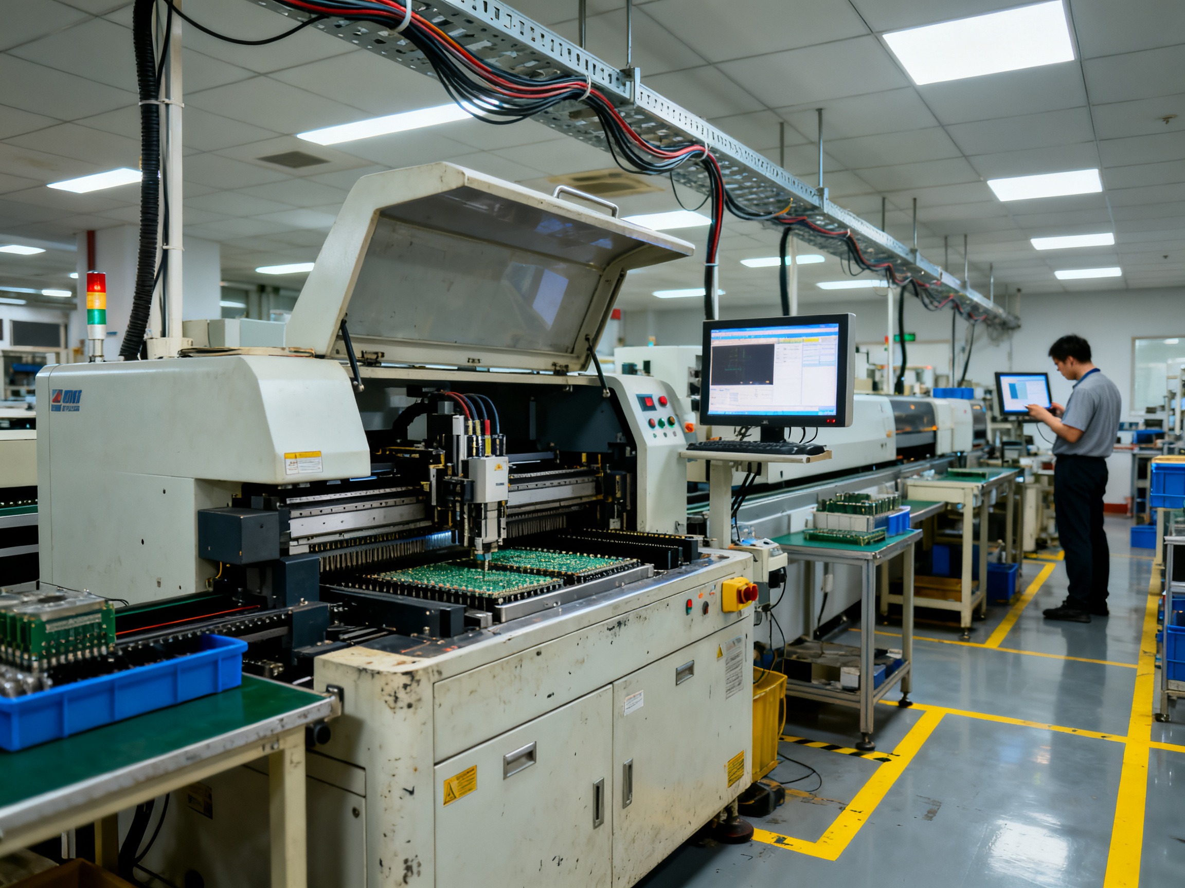
Nozzle Selection: This Matters More Than You’d Think
The nozzle is where precision happens. Get it wrong and you’ll fight bridging and fill problems forever.
Key parameters: aperture geometry must match your target joint size (standard 0.8mm hole needs 1.2-1.5mm aperture), nozzle style must match your application method, thermal mass affects lead-free processing, and component clearance is often the limiting factor on dense boards.
نصيحة من الخبراء: Always verify physical clearance with your actual fixture in place. CAD clearance calculations miss nozzle approach angles and flux spray patterns. A connector body interfered with a nozzle approach path, causing two weeks of production delays on an automotive module before anyone caught it.
Fixture Design: The Foundation of Repeatability
Fixtures control coplanarity, enable thermal isolation, provide fiducial references, and protect reflowed components. Poor fixture design undermines even the best nozzle selection.
Core requirements: full board support prevents flex during solder contact, thermal shielding protects top-side components from heat, fiducials ensure registration accuracy within ±0.1mm, and quick-change designs (T-slots, magnetic bases) reduce changeover friction.
For mixed-technology boards with high-density areas, dedicated fixtures for selective soldering that maximize thermal shielding often differ from standard production fixtures.
مسار العمل الانتقائي للحام من البداية إلى النهاية
Here’s what the actual selective soldering workflow looks like from start to finish. No oversimplified version, the real thing that production teams run every shift.
Pre-Production Preparation
Before a single board touches the machine, there’s homework to do. Review your Gerber files and assembly data to verify hole sizes, lead protrusions, and component placements. Classify your solder joints into visible fillets versus hidden or partially hidden barrel joints. Hidden joints need X-ray verification because you cannot judge hole fill by appearance alone. This classification drives your entire inspection plan.
Verify your board finish and component materials match your process. Check thermal mass estimates for heavy components that might need extra preheat. Establish keep-out zones around the solder nozzle and for protecting reflowed SMT areas. One tip from the field: mark your highest-risk thermal joints on the assembly drawing before creating any recipes.
Recipe Validation Checklist
- [ ] Gerber and assembly data reviewed
- [ ] Joints classified by visibility and criticality
- [ ] Board finish and component materials verified
- [ ] Keep-out zones established and marked
- [ ] Recipe parameters documented and locked
- [ ] First-article sample prepared
The Core Sequence
The end-to-end workflow follows this order every single time:
1. Board Loading and Fixturing
Load the board and secure it with fixtures that control coplanarity, enable thermal isolation, and provide fiducial references. Registration accuracy needs to stay within plus or minus 0.1mm.
2. Flux Application
Targeted flux dispensing onto through-hole leads only. Adjacent SMT parts stay clean. Confirm flux volume, pattern, and actuation repeatability through your flux calibration check.
3. Preheat Stage
Bring the board up to 80 to 150 degrees Celsius on the topside depending on your flux activation requirements and the thermal mass involved. This step prevents thermal shock and activates the flux properly.
4. Solder Application
The nozzle delivers molten solder at 250 to 265 degrees Celsius for lead-free SAC alloys. Contact dwell time runs 2 to 6 seconds per joint depending on geometry and thermal mass.
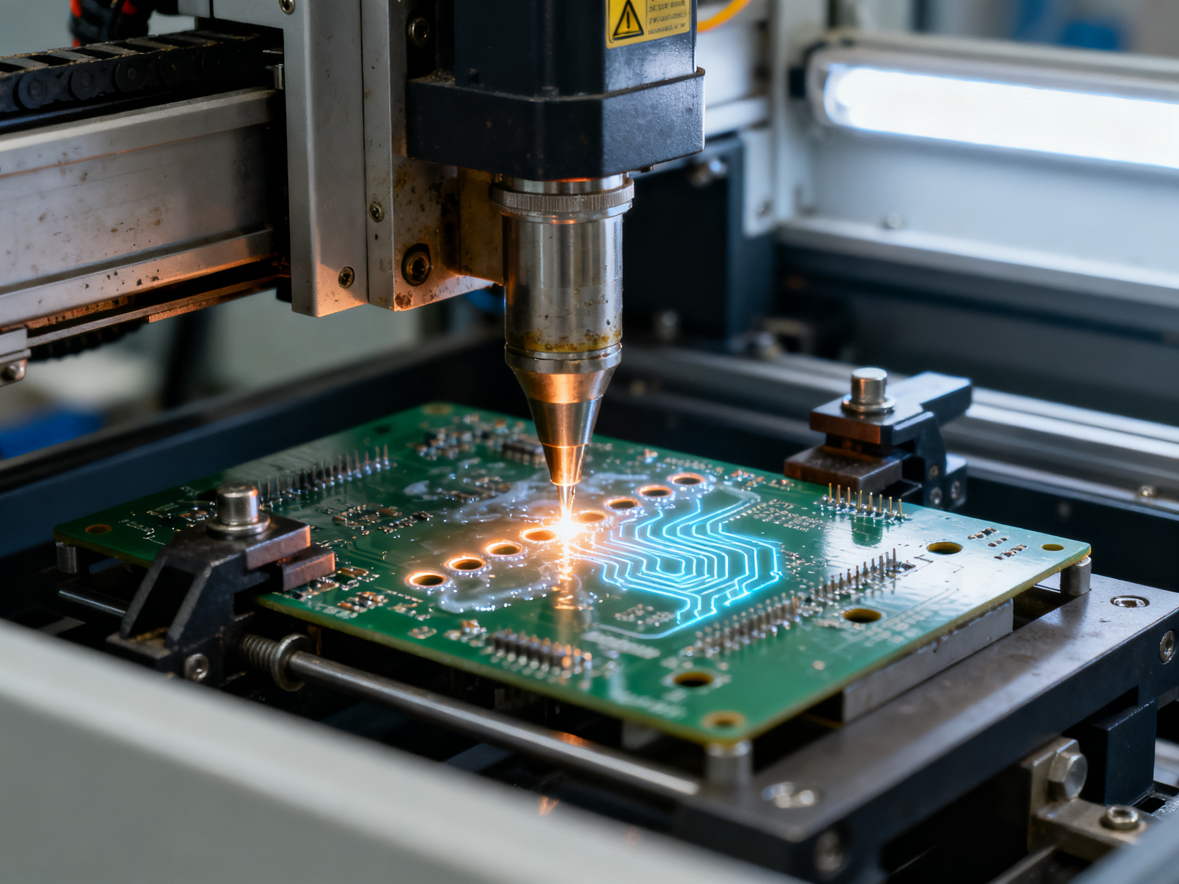
5. Inspection
AOI catches visible defects. X-ray handles hidden barrel fill verification for critical joints.
6. Process Feedback
Inspection data flows back into recipe adjustments with documented change control.
Process Control Table
| Parameter | Typical Range | Control Method | SPC Check Frequency |
|———–|—————|—————-|———————|
| Solder Temperature | 250-265°C | Thermocouple verification | Every shift |
| Preheat Topside | 80-150°C | Thermocouple profile | Every board family |
| Contact Dwell | 2-6 seconds | Timer verification | Every 10 boards |
| Flux Volume | ±10% of recipe | Gravimetric check | Daily |
| Nozzle Alignment | ±0.1mm | CMM or test fixture | Weekly |
| Hole Fill | 75-100% (Class 3) | X-ray sampling | First article + hourly |
From Our Experience: We ran a recipe validation on an automotive control module with mixed thermal masses. Baseline showed 62% hole fill on smallsignal pins next to a heavy through-hole connector. The intervention was adding 15 seconds to preheat time and shifting the nozzle approach angle by 8 degrees to avoid the thermal shadow. Measured result: 94% hole fill consistently across three shifts. Documentation went straight into the locked recipe parameters.
Inspection and Feedback Loop
Visual inspection handles the obvious stuff, but selective soldering has over 100 interacting parameters. Trend monitoring catches drift that one-time setup approval misses. Track hole fill rates, bridge occurrences, wetting defects, and thermal excursions on control charts. Feed that data back into recipe adjustments with documented change control so you know exactly what changed and why.
IPC-A-610 Class 3 requires minimum 75% hole fill for high-reliability assemblies, though 100% is always the target. For hidden or critical joints in aerospace and medical work, X-ray is the only practical non-destructive verification method. Set your sampling plan based on board complexity, not gut feeling. Dense mixed-technology boards need tighter sampling intervals than simple through-hole assemblies.
The closed-loop matters most when you’re running high volume. A small drift in solder temperature or preheat that barely shows on one board becomes a major defect spike across hundreds. SPC keeps you ahead of problems instead of chasing them after the fact.
Statistical process control isn’t optional for serious production. It transforms selective soldering from a setup-and-hope process into something you actually control.
الوقاية من العيوب الشائعة ومعالجة الأسباب الجذرية للمشكلات
Here’s something nobody tells you when you first run selective soldering: the process has over 100 interacting parameters. Flux activity, preheat profiles, solder temperature, contact timing, nozzle geometry, fixture alignment, board design, component thermal mass, and operator recipe control all work together. When something goes wrong, the instinct is to grab one knob and crank it. Don’t.
Randomly bumping up solder temperature or dwell time usually trades one defect for another. Too much heat creates component damage or flux char. Too much dwell time disturbs joints that were already good. The smarter approach is systematic root-cause analysis.
Symptom-Cause-Action Troubleshooting Table
| Defect | Primary Causes | First Action |
|——–|—————|————-|
| Insufficient hole fill | Low solder temp, short dwell, weak flux, poor preheat | Check solder temperature and preheat profile first |
| Solder bridging | Tight spacing, excess flux, wrong nozzle size, nozzle path issues | Verify pad-to-pad clearance and reduce flux volume |
| Icicles | Low solder temp, fast withdrawal, nozzle oxidation | Slow withdrawal speed and verify solder temperature |
| Non-wetting | Oxidized pads/leads, bad surface finish, weak flux activity | Check component storage and verify flux chemistry |
| Skips | Missed flux coverage, nozzle misalignment | Inspect flux pattern and verify nozzle alignment |
| Disturbed joints | Premature board movement, unstable fixtures | Check fixture support and verify contact timing |
| Flux residue | Over-application, insufficient preheat activation | Adjust flux volume and verify preheat temperature |
| Component damage | Excessive heat exposure, insufficient thermal shielding | Review thermal isolation and preheat profile |
IPC-A-610 Class 3 requires minimum 75% hole fill for high-reliability assemblies IPC-A-610, and any bridge wider than a lead thickness counts as a defect needing rework. If you’re seeing more than five solder balls per joint, that’s also flagged as a defect.
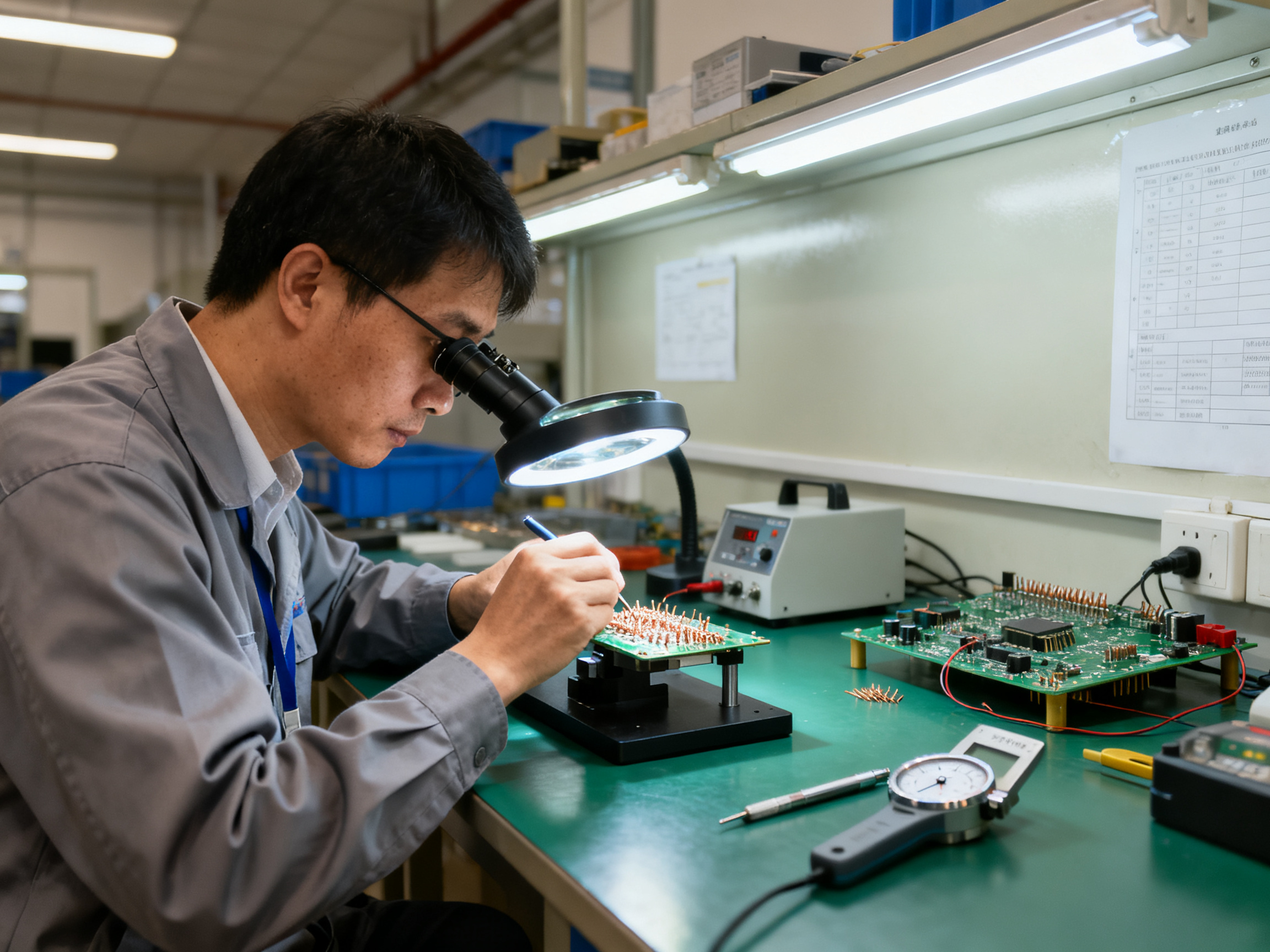
Defect Investigation Case Study Template
When something goes wrong on a production run, document your investigation using this structure:
Baseline: Record defect rate, sample size, board family, and measurement method before any changes.
Intervention: State exactly what you changed, why you chose that parameter, and what you expected to happen.
Result: Report measured outcome against baseline with sample size confirmation.
What this looks like in practice: We had a run where hole fill kept dropping on small signal pins near a heavy through-hole connector. Baseline showed 58% fill on 45 boards. Instead of just cranking up temperature, we profiled the thermal mass difference. Turned out the heavy connector was acting as a heat sink. The fix was adding preheat time and adjusting the nozzle approach angle, not changing solder temperature. Result was 91% fill consistently.
نصيحة من الخبراء: Cluster defects by board zone before troubleshooting. If bad joints all appear near a specific component or board area, you probably have a thermal shadow or accessibility issue, not a process drift. Design sensitivity often masquerades as recipe failure.
The key insight is simple: symptoms point you toward a zone. Causes narrow down the list. Controlled one-at-a-time changes verify the fix. Document everything so the next shift knows what changed and why.
Integrating Selective Soldering Into a High-Volume SMT Line
Selective soldering only delivers its promised benefits if it slots into your line without creating new bottlenecks. That means thinking through every handoff point before you power up.
Line Integration: The Big Picture
Your selective system sits between reflow and final inspection. Boards flow in from upstream operations already carrying their SMT assembly. The selective machine handles through-hole joints. Then boards continue to AOI, X-ray if needed, cleaning, test, and rework before packing.
For the handshakes between machines, IPC-HERMES-9852 has become the preferred protocol in 2026 for richer board and job data exchange. SMEMA still works for basic handoff signals on older equipment. Either way, verify that your selective machine accepts the same conveyor height, board size range, and transfer direction your SMT placer and reflow oven output The Hermes Standard.
Traceability ties everything together. Bind each PCB serial number to the recipe used, flux lot, solder lot, operator ID, and inspection results. That data feeds your MES and supports IPC-1782-style traceability requirements for aerospace and medical customers.
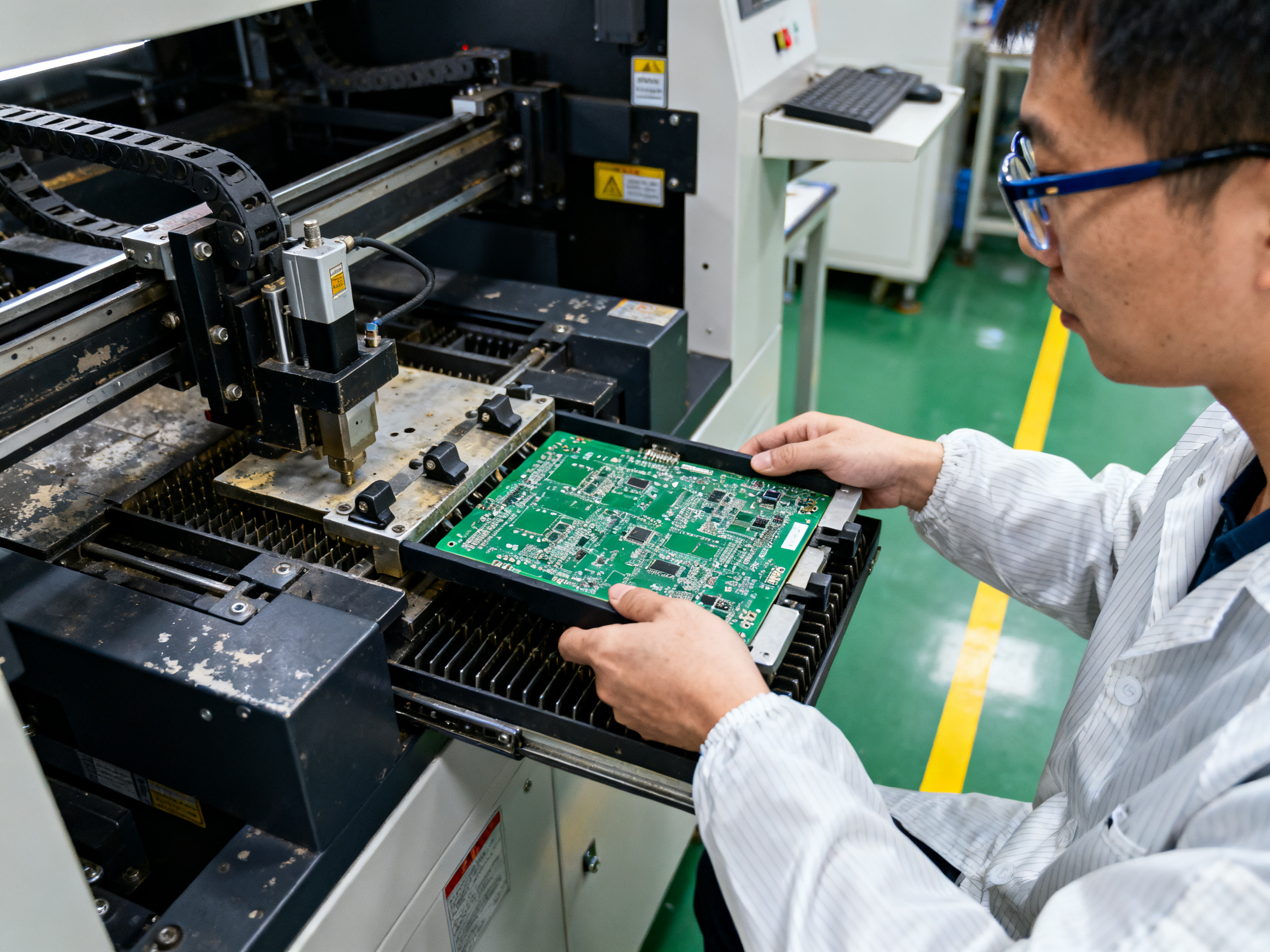
Operational Essentials
Operator training covers recipe selection, changeover procedures, consumable replenishment, and what to do when something goes sideways. Build escalation paths for quality escapes and equipment alarms.
Preventive maintenance keeps nozzles clean and aligned. Stock spare nozzles and fixture components so changeovers don’t stall production. Flux and solder need daily checks and regular replenishment based on usage rates.
Compliance and Safety Checklist
Lead-free selective soldering runs 20 to 40 degrees Celsius hotter than traditional tin-lead, which means more fumes and tighter ventilation requirements. Local exhaust ventilation at the solder source is non-negotiable. ESD controls protect sensitive components throughout handling. Machine guarding keeps operators safe from moving axes and hot surfaces.
Deployment Checklist:
- [ ] Line integration verified with upstream/downstream equipment
- [ ] IPC-HERMES-9852 or SMEMA communication tested
- [ ] Traceability system binding PCB serial to recipe/flux/solder lots
- [ ] Operator training completed and documented
- [ ] Preventive maintenance schedule established
- [ ] Spare nozzles and fixtures stocked
- [ ] Fume extraction system validated and operational
- [ ] ESD controls in place and verified
- [ ] Machine guarding inspected and functional
- [ ] First article approved before production launch
Vendor Questions to Ask:
- What throughput can you demonstrate on boards matching our density?
- How does your recipe management handle barcode-driven parameter selection?
- What traceability data can you export, and in what format?
- What are your warranty terms and response time for service calls?
- Can you provide audited defect rate data with sample sizes?
Responsibility Matrix:
| Task | Engineering | Production | Quality | Maintenance | Procurement |
|——|————-|————|———|————-|————-|
| Recipe setup | Primary | Support | Approve | | |
| Line integration | Primary | Support | Verify | Support | Support |
| Daily operation | Support | Primary | Inspect | On-call | |
| Preventive maintenance | Support | | | Primary | |
| Spare parts | Support | | | Recommend | Primary |
| Compliance documentation | Approve | | Primary | | Support |
Getting selective soldering right in a high-volume line takes planning. But once it’s dialed in, your throughput climbs and defect rates drop. The investment in integration upfront pays back fast.
Validating ROI, Quality, and Scale Before Purchase
Before signing any purchase order, run a controlled pilot. This step separates marketing claims from what actually happens on your production floor with your boards, your materials, and your operators.
A pilot should test boards that actually challenge the equipment, not easy samples. Pick the hardest joint geometries in your mix, run at your expected production volume, and use the lead-free materials you plan to run in 2026. You need 30 to 50 boards minimum per board family to catch variability. Track first-pass yield, defect rates per million opportunities, hole fill percentages, cycle time, and changeover duration. Measure uptime, consumables used, and rework hours needed. Calculate your actual cost per board.
| Metric | Baseline | Pilot Result | Target |
|——–|———-|————–|——–|
| First-pass yield | Manual/wave current | Measured | >98% |
| DPMO | Current defect rate | Measured | <500 |
| hole fill | current compliance measured>75% |
| Cycle time | Minutes per board | Measured | <60 sec |
| changeover | minutes between families measured <15 min uptime availability percentage>95% |
Factory acceptance testing matters most. Watch the supplier run boards with your actual materials. Verify throughput, quality outcomes, and recipe repeatability under real conditions, not just sales floor demos.
Decision gates keep you honest: technical acceptance first, then quality approval, then production readiness, and finally commercial terms. Skip the “up to” improvements that lack actual sample sizes. Demand named customer references with verified data.
From Our Experience: We saw a vendor claim their mini selective wave soldering machine hit 40 boards per hour. The catch was that number came from a simple single-header board with only 4 joints. Our automotive control module has 87 through-hole joints across mixed thermal zones. Real throughput landed at 22 boards per hour after preheat and inspection overhead. Always pilot with your actual product.
مسار عملي لإتقان اللحام الانتقائي
The governing principle comes down to one thing: match your soldering method, nozzle, fixture, recipe, and inspection plan to what your board actually needs. Joint geometry and production requirements drive every decision, not machine brand names or what the spec sheet claims.
Here’s the sequence that works. First, audit your current defect data and classify joints by visibility and criticality. Second, run a representative pilot with your hardest board family, not the easy samples. Third, validate results against IPC-A-610 Class 3 acceptance criteria. Fourth, integrate traceability and maintenance controls before you scale up.
Final Decision Checklist:
| Factor | Action Required |
|——–|—————–|
| Joint classification | Separate visible fillets from hidden barrel joints |
| Pilot scope | Test hardest geometry, minimum 30 boards per family |
| Acceptance standard | Validate against IPC-A-610 Class 3 (75% minimum fill) |
| Traceability | Bind PCB serial to recipe, flux lot, solder lot, operator ID |
| Maintenance | Establish PM schedule and stock spares before launch |
رؤية «برو»: Cluster defects by board zone before troubleshooting. Design sensitivity often masquerades as recipe failure. If bad joints concentrate near one component, you probably have a thermal shadow or accessibility issue.
From Our Experience: Equipment selection should follow measured process capability and line compatibility, not machine size or headline throughput numbers. Pilot results tell you more than any sales pitch ever will.
Relevant Standards:
- IPC-A-610 Acceptability Criteria – Visual inspection and workmanship standards
- J-STD-001 Soldering Requirements – Materials and process requirements
- IPC-2221 PCB Design Standard – Design-for-manufacture guidelines
The path forward is clear. Start with your actual defect data, validate under real conditions, then build the controls that keep quality consistent shift after shift.