



Zveřejněno: 10 August 2026
Poslední aktualizace: 10 August 2026
Čas na čtení: 10 minutes
What Solder Paste Mixing Tools Do in SMT Assembly
In high-volume PCB assembly, pájecí pasta is the foundation of every connection. Get it wrong, and you’re chasing defects down the line. Get it right, and your lines run smooth.
Solder paste mixing tools solve a specific problem. When paste comes out of the fridge, it’s not ready to use. It needs to thaw fully at room temperature, which takes 3 to 6 hours depending on the container size. Once thawed, the metal powders and flux can separate during storage. Mixing brings everything back together for consistent viscosity and particle distribution. The goal is simple: restore the paste to its original, usable state without introducing air bubbles or changing its chemistry.
Two main approaches exist. Manual stirring works well for smaller quantities, typically taking 1 to 5 minutes. Machine mixing, using planetary or centrifugal equipment, handles larger production batches and ensures more uniform results. Professional mixing stations often include programmable timers and controlled speed settings.
Here’s why this matters for your defect rate. Research shows that about 60 to 70 percent of SMT defects trace back to solder paste printing problems [wifitalents.com/smt-industry-statistics/]. Poor mixing feeds directly into that number. When paste isn’t properly homogenized, you get inconsistent paste deposits, poor wetting, and increased voiding. For fine-pitch components and BGA packages, this is especially costly.
Expert Tip: How to confirm solder paste is ready for printing without overmixing or introducing process variation.
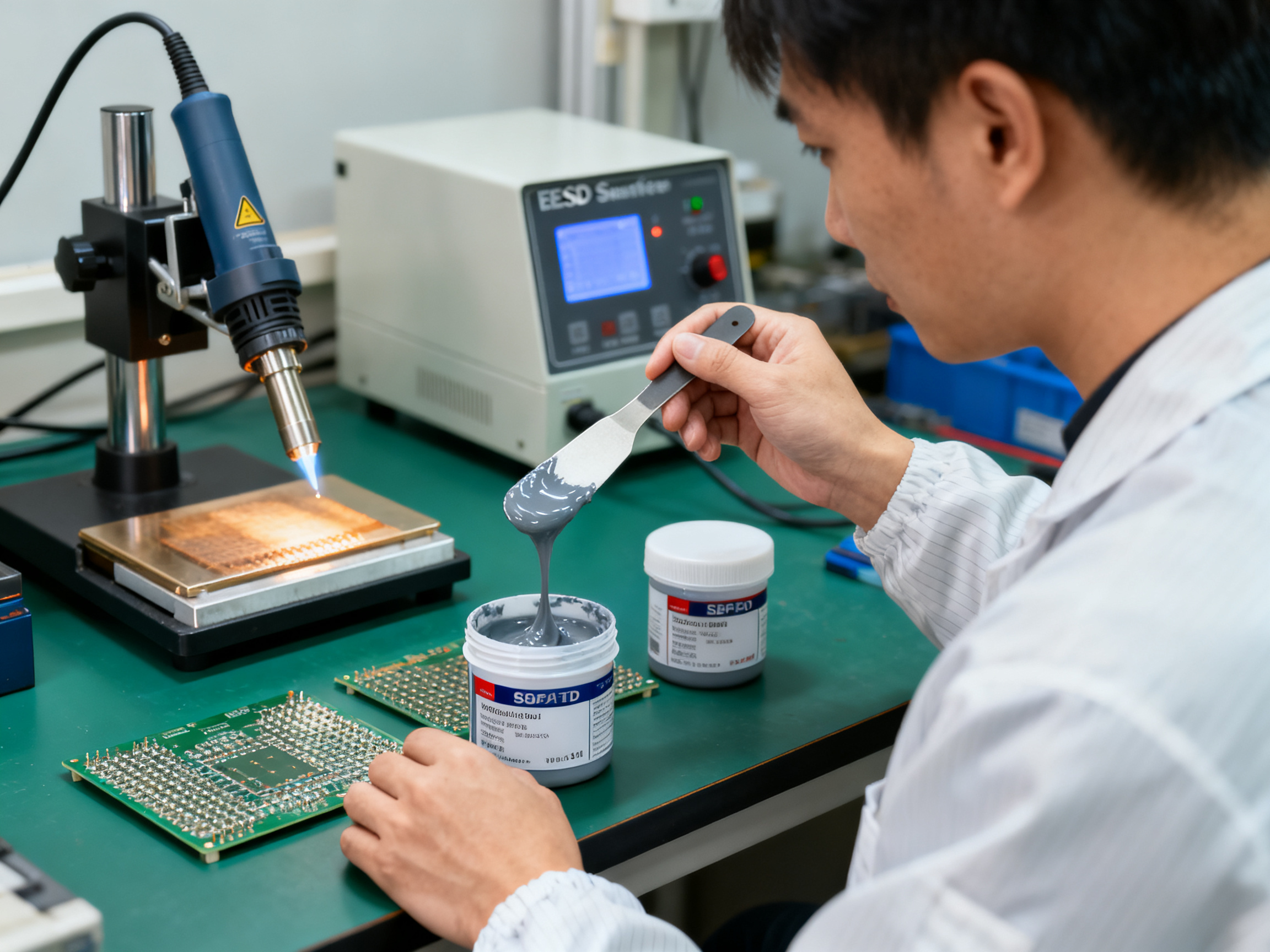
The key is to follow the paste manufacturer’s technical data sheet for mixing time and method. Visual checks help too: the paste should look uniform, with a consistent sheen and no visible separation. A good test is to lift a small amount with a spatula and watch how it falls. It should flow smoothly, like thick paste, not chunky or stiff.
The real value of mixing equipment is repeatability. Human stirring varies between operators and shifts. Controlled mixing eliminates that source of variation. Your SPI data will tell you whether paste deposits are hitting target values, and consistent mixing supports those numbers.
About the Author
Jace Liu is [insert verified role, company affiliation, and SMT/electronics manufacturing experience]. His work focuses on [insert verified area: SMT equipment, soldering process optimization, production quality, or electronics assembly].
Credentials pending verification. This section will be updated once official bio information is confirmed.## What Solder Paste Mixing Tools Do in SMT Assembly
In high-volume PCB assembly, solder paste is the foundation of every connection. Get it wrong, and you’re chasing defects down the line. Get it right, and your lines run smooth.
Solder paste mixing tools solve a specific problem. When paste comes out of the fridge, it’s not ready to use. It needs to thaw fully at room temperature, which takes 3 to 6 hours depending on the container size. Once thawed, the metal powders and flux can separate during storage. Mixing brings everything back together for consistent viscosity and particle distribution. The goal is simple: restore the paste to its original, usable state without introducing air bubbles or changing its chemistry.
Two main approaches exist. Manual stirring works well for smaller quantities, typically taking 1 to 5 minutes. Machine mixing, using planetary or centrifugal equipment, handles larger production batches and ensures more uniform results. Professional mixing stations often include programmable timers and controlled speed settings.
Here’s why this matters for your defect rate. Research shows that about 60 to 70 percent of SMT defects trace back to solder paste printing problems [wifitalents.com/smt-industry-statistics/]. Poor mixing feeds directly into that number. When paste isn’t properly homogenized, you get inconsistent paste deposits, poor wetting, and increased voiding. For fine-pitch components and BGA packages, this is especially costly.
Expert Tip: How to confirm solder paste is ready for printing without overmixing or introducing process variation.
The key is to follow the paste manufacturer’s technical data sheet for mixing time and method. Visual checks help too: the paste should look uniform, with a consistent sheen and no visible separation. A good test is to lift a small amount with a spatula and watch how it falls. It should flow smoothly, like thick paste, not chunky or stiff.
The real value of mixing equipment is repeatability. Human stirring varies between operators and shifts. Controlled mixing eliminates that source of variation. Your SPI data will tell you whether paste deposits are hitting target values, and consistent mixing supports those numbers.
Types of Solder Paste Mixing Equipment
Not all mixers work the same way. The method you choose affects air bubble content, viscosity consistency, and ultimately your defect rate.
| Mixer Type | Best Use Case | Throughput | Quality Control | Typical Cost |
|————|—————|————|—————–|—————|
| Manual stirring | Small runs, prototyping | Low (1-5 min per batch) | Operator dependent | $10-$50 |
| Centrifugal mixer | Medium production batches | Medium | Moderate, speed-dependent | $500-$2,000 |
| Vacuum mixer | Void-sensitive assemblies, BGAs | Medium to High | High, minimal air entrapment | $2,000-$8,000 |
| Programmable industrial | High-volume automated lines | Very High | Full SPC integration | $5,000-$20,000+ |
Manual stirring seems simple. You grab a spatula and go. But it’s slow for production runs, and results vary wildly between operators. One person might stir for 2 minutes, another for 4. The next shift might be even more different. This variation shows up in your SPI data.
Centrifugal mixers spin the paste jar at high speed. They homogenize paste faster than hand stirring and reduce some of the operator dependency. But there’s a catch: aggressive spinning can introduce air rather than remove it. Paste manufacturers often recommend limiting centrifugal mixing time or avoiding it altogether for certain formulations.

Vacuum mixers pull air out during the mixing cycle. This matters for void-sensitive work like BGA assemblies where trapped gas expands during reflow and creates reliability problems. The vacuum also helps restore original rheology after cold storage.
Programmable industrial units sit at the top of the range. They handle large jars, log mixing parameters for traceability, and can integrate with MES systems. You get full repeatability and documentation. The tradeoff is cost and floor space requirements.
Why Lead-Free Paste Demands More Attention
Lead-free solder paste behaves differently than traditional tin-lead formulations. The higher melting points mean more oxidation risk during handling. When you mix paste, you’re working with metal powders that want to react with oxygen. Less air exposure during mixing means less oxidized metal and better wetting at reflow.
Temperature recovery after thawing also matters more for lead-free. Most manufacturers specify 4 to 6 hours at room temperature, and they explicitly forbid using heat to speed things up. Microwaving or hot water baths alter paste chemistry in ways that cause downstream problems.
Jar compatibility deserves attention too. Standard solder paste cans work with most mixers, but sizes vary. Check that your equipment accepts your typical container dimensions before buying. Some facilities transfer paste between jars, which introduces contamination risk and extra handling steps.
The bottom line is this: mixing paste isn’t optional prep work. It’s a process step that directly affects your defect rate and final assembly quality. Getting it right with appropriate equipment and documented procedures pays back in fewer rework cycles and better first-pass yield.
How to Choose the Best Solder Paste Mixers for Production Lines
Choosing a solder paste mixer isn’t a one-size-fits-all decision. Your production context determines what features matter most.
Start by mapping your operation to the right mixer tier. Prototyping labs and low-volume runs usually get by with manual stirring or a basic centrifugal unit. Mid-volume assembly operations benefit from programmable mixers with timer control. High-volume smartphone manufacturing and semiconductor packaging demand industrial-grade equipment with full traceability and MES integration. Military and aerospace electronics shops need documented processes that satisfy audit requirements and IPC standards.
Here’s a buyer checklist I use when evaluating mixers for production lines:
Capacity and Compatibility
- Jar size compatibility with your typical paste container (60-67mm is standard, but verify)
- Maximum batch weight the mixer handles
- Whether it accepts your existing paste jar brands
- Floor space requirements for your facility
Process Control Features
- Programmable speed settings (typical range: 300-1400 RPM)
- Adjustable timer with sufficient range for your paste type
- Repeatability of mixing parameters across batches
- Data logging or traceability output for documentation
Operational Considerations
- Safety interlocks and emergency stop functions
- Noise level, especially for operators working nearby all day
- Maintenance requirements and service intervals
- Availability of spare parts and consumables
Supplier Assessment
Before signing a purchase order, evaluate the vendor. Ask about calibration guidance, installation support, and response times for service requests. Check whether documentation meets your quality system requirements. A mixer that costs less upfront becomes expensive if you can’t get parts or support when something breaks.
| Evaluation Criteria | Weight for Prototyping | Weight for Production | Weight for Military/Aero |
|———————|————————|———————–|————————–|
| Consistency and repeatability | Medium | High | Critical |
| Throughput | Low | High | Medium |
| Operator control | High | Medium | Medium |
| Total cost of ownership | Medium | High | High |
| Documentation and traceability | Low | Medium | Critical |
The mixer’s consistency directly affects your defect rate. Research shows that 60-70 percent of SMT defects trace back to solder paste printing, and inconsistent paste preparation feeds into that number. A controlled mixer eliminates one source of operator variation between shifts and batches.
Weighing these factors against your actual production volume and quality requirements helps you avoid both underbuying (choosing equipment that creates defects) and overbuying (paying for features you won’t use).## Best Tools for Soldering: From Benchtop Work to Line Support
Not all soldering tools are created equal. Pick the wrong station for lead-free work, and you’ll fight with poor wetting and cold joints all day. Get it right, and the same rework that used to take 20 minutes takes 5.
Here’s what actually matters when you’re shopping for soldering gear in 2026.
Temperature-controlled stations are non-negotiable for anything beyond occasional hobby work. Your tip temperature needs to stay stable under load. For lead-free solder, you’re typically working in the 240°C to 280°C range, sometimes higher depending on the mass. A station that overshoots or drifts defeats the purpose.
Look at thermal recovery speed, not just wattage. When you touch a large copper pad or a grounded component, heat disappears fast. The station needs to recover quickly or your joint quality suffers. PID-controlled units handle this better than simple on/off designs.
Tip geometry matters more than most people realize. A fat tip holds more heat but gives you less precision. Fine-pitch work on QFN packages or small SMD components needs a fine tip. Large ground planes need something chunkier. Having three or four tip sizes available covers most situations.
Pro Insight: Why thermal recovery and tip selection matter more than headline wattage for lead-free soldering reliability.
Hot air rework stations handle a different job. They’re for reflowing components, not hand soldering. BGA rework and QFN lift-and-replace work demand controlled airflow, not just heat. Look for adjustable air volume and temperature stability under load.
Flux deserves more attention than it usually gets. Use the right type for your process. No-clean flux leaves residue that doesn’t need removal, which saves steps. Rosin-based flux works well but requires cleaning afterward. For lead-free assemblies, a quality no-clean flux often makes the difference between good wetting and sluggish flow.
Fume extraction isn’t optional anymore. Breathing flux fumes all day is bad for you, and it’s also bad for the work. Source capture close to the joint works better than room air filtration. Look for units with HEPA and activated carbon filtration.
| Tool | Role | Must-Have Specification | Common Mistake |
|——|——|————————|—————-|
| Soldering station | Hand soldering, rework | ±5°C temperature accuracy, PID control | Buying based on wattage alone |
| Hot air station | Reflow, component rework | Adjustable airflow, stable temp under load | Using for hand soldering jobs |
| Soldering tips | Heat transfer to joint | Match size to work; keep tinned | Letting tips oxidize dry |
| Flux | Improve wetting | Correct type for your process | Skipping it on lead-free work |
| Fume extraction | Protect operators and work | Source capture, HEPA filtration | Room-only filtration |
| Tweezers | Component handling | Anti-magnetic, fine point | Wrong tip size for the part |
| PCB holders | Stabilize boards | Adjustable clamp pressure | Scratching pads or boards |
| ESD mat and grounding | Prevent static damage | Surface resistance 10^6-10^9 ohms | No grounding strap |
ESD protection gets overlooked until something dies mysteriously. An ESD-safe workstation includes the mat, a grounding cord, wrist straps for operators, and properly grounded tools. For sensitive ICs and high-value assemblies, this isn’t optional.
Tweezers and PCB holders seem minor. They aren’t. Damaging a small component during placement causes failures that show up later, sometimes after the board is in service. Anti-magnetic tweezers with fine tips handle 0402 and 0201 parts without slipping.
The split between bench tools and line equipment matters too. A bench station serves one operator doing repair, prototyping, or low-volume work. Production lines need equipment that integrates with MES systems, logs process data, and supports repeatability across shifts. Shenzhen Chuxin Electronic Equipment Co., Ltd. builds přetavovací pecs and wave soldering machines designed for exactly that kind of production floor integration.
For operator benches, prioritize control and comfort. For production support, prioritize documentation and repeatability.
How to Choose a Wire Stripper for Electronics Assembly
Picking the wrong wire stripper costs more than the tool itself. It costs you failed inspections, intermittent faults, and reworks that eat your day.
The type of wire stripper you need depends on five things: conductor gauge, insulation material, production volume, repeatability requirements, and whether you can afford any nicks in the strands.
Manual strippers work for low-volume work and prototyping. You squeeze, the blades cut through insulation, and you pull. The problem? Results vary between operators. One person pulls too hard on fine 28 AWG wire and breaks half the strands. Another is too gentle and leaves insulation behind. For quality-critical work, this variation adds up fast.
Automatic strippers clamp and pull in one motion. They’re faster for production runs and reduce operator fatigue. But you still need to set the correct depth and gauge. Get it wrong, and you’re back to nicked conductors.
Thermal strippers melt through insulation without touching the conductor. These work great for magnet wire and enamel-coated wire where mechanical contact would damage the fine strands. The tradeoff is fumes, so you need proper ventilation.
Pneumatic and programmable strippers sit at the high end of production. They offer consistent strip lengths, programmable settings, and cycle times measured in seconds. For automotive or aerospace work where documentation matters, these units can log parameters for traceability.
| Wire Type | Gauge Range | Recommended Stripper | Common Mistakes |
|———–|————-|———————|—————-|
| Hookup wire (PVC) | 10-26 AWG | Manual or automatic | Wrong depth setting |
| High-temp wire (Kapton) | 20-30 AWG | Thermal or precision manual | Using mechanical stripper too hard |
| Multiconductor cable | 16-24 AWG | Automatic with multiple slots | Overstripping, exposing too much |
| Magnet/enamel wire | 28-44 AWG | Thermal or chemical | Scraping instead of burning coating |
Here’s what happens when stripping goes wrong. A nicked strand doesn’t carry full current. Over time, the nick works-harden and breaks. Your board fails in the field six months later. Intermittent faults are the worst to debug. Crimp connections fail prematurely when even a few strands are severed. IPC inspectors flag these defects immediately.
For fine-gauge work, we always recommend testing on scrap pieces first. Set your tool, strip three samples, and check under magnification before touching production wire.
Pro Insight: Why thermal recovery and tip selection matter more than headline wattage for lead-free soldering reliability.
The right stripper for your operation isn’t necessarily the most expensive one. It’s the one that matches your wire types, production volume, and quality requirements without introducing defects your inspection process will catch.## Multimeters for Beginners in Assembly and Maintenance Teams
If you’re new to electronics assembly or maintenance, a multimeter is probably the first piece of test gear you’ll pick up. It’s the tool that answers basic questions: Is this circuit dead? Is that wire broken? Is the power rail at the right voltage?
Most multimeters do the same core things. They measure voltage (DC and AC), resistance, and continuity. Higher-end units add diode testing, current measurement, capacitance, and frequency. For assembly work, you really need voltage, resistance, and continuity. The extras are nice but not always necessary.
Here’s what beginners should actually look for when buying a multimeter in 2026.
Auto-ranging saves time. Instead of guessing which voltage range to select, an auto-ranging meter figures it out for you. This reduces errors and keeps you from accidentally blowing a fuse by selecting the wrong function.
A clear display matters. If you can’t read the numbers without squinting, the tool causes more problems than it solves. Backlit screens help in dim assembly areas.
Input protection is non-negotiable. This keeps the meter from dying if you accidentally measure across a live circuit at the wrong setting. Look for fused current inputs and overload protection on all ranges.
CAT ratings tell you where you can safely use the meter. CAT I meters work on battery circuits. CAT II suits outlet measurements. CAT III and CAT IV are for industrial wiring and distribution panels. Using a CAT I meter on building wiring is asking for trouble.
From Our Experience: How disciplined inspection and cleaning routines can reduce rework before defects reach final test.
Continuity response speed matters for production use. Faster beep response helps you move through harness checks quickly without waiting for the meter to catch up.
| Meter Type | Best For | Price Range | Key Feature |
|————|———-|————-|————-|
| Basic handheld | Hobby, simple repairs | $20-$50 | Auto-ranging, basic functions |
| Industrial handheld | Assembly lines, maintenance | $100-$300 | CAT III/IV, data hold, robust |
| Bench meter | Calibration labs, R&D | $300-$1000+ | High accuracy, interfaces |
For assembly line work, an industrial handheld with CAT III rating handles most situations you’ll encounter. Keep it calibrated per your quality system requirements, and replace the fuses when they blow.
Calibration matters for documentation. If your quality system requires traceable measurements, keep calibration records current. Most manufacturers recommend annual recalibration for production meters.## Inspection, Cleaning, and Support Gear That Protects Assembly Quality
Microscopes, AOI support tools, cleaning brushes, IPA wipes, tip cleaners, storage cabinets, and ESD-safe containers. These things don’t show up on production line diagrams, but they determine whether your defect rate stays under 50 DPMO or climbs into the thousands.
In high-reliability sectors like automotive, aerospace, military electronics, and semiconductor packaging, defects that reach final test cost exponentially more to fix than defects caught at the station. An inspection microscope that costs a few hundred dollars might save you thousands in rework and warranty claims.
The inspection workflow basics
PCB inspection typically follows this sequence: paste printing, SPI check, component placement, reflow, AOI, X-ray for hidden joints, and final verification. Each checkpoint has tools designed for specific failure modes.
A good stereo microscope (10x to 45x magnification) handles most component and solder joint inspection. Digital USB microscopes add recording capability for defect documentation. For BGAs and QFN packages where joints hide underneath, X-ray inspection becomes essential.
AOI systems catch visible defects like bridging, tombstoning, and insufficient paste deposits. But they need regular calibration and proper lighting to work right. SPI (Solder Paste Inspection) equipment validates paste deposits before reflow, catching problems before they become defects.
Cleaning and maintenance gear
IPA wipes and brushes remove flux residue and debris. Isopropyl alcohol at 90% or higher purity works well for no-clean processes. Anti-static cleaning brushes prevent static damage during workstation cleanup. For tip maintenance, a brass tip cleaner extends iron tip life without damaging the plating.
Storage matters too. Soldering tip holders keep tips clean and ready. Desiccant cabinets protect moisture-sensitive components (MSDs) from humidity damage. ESD-safe containers prevent static discharge from killing sensitive ICs.
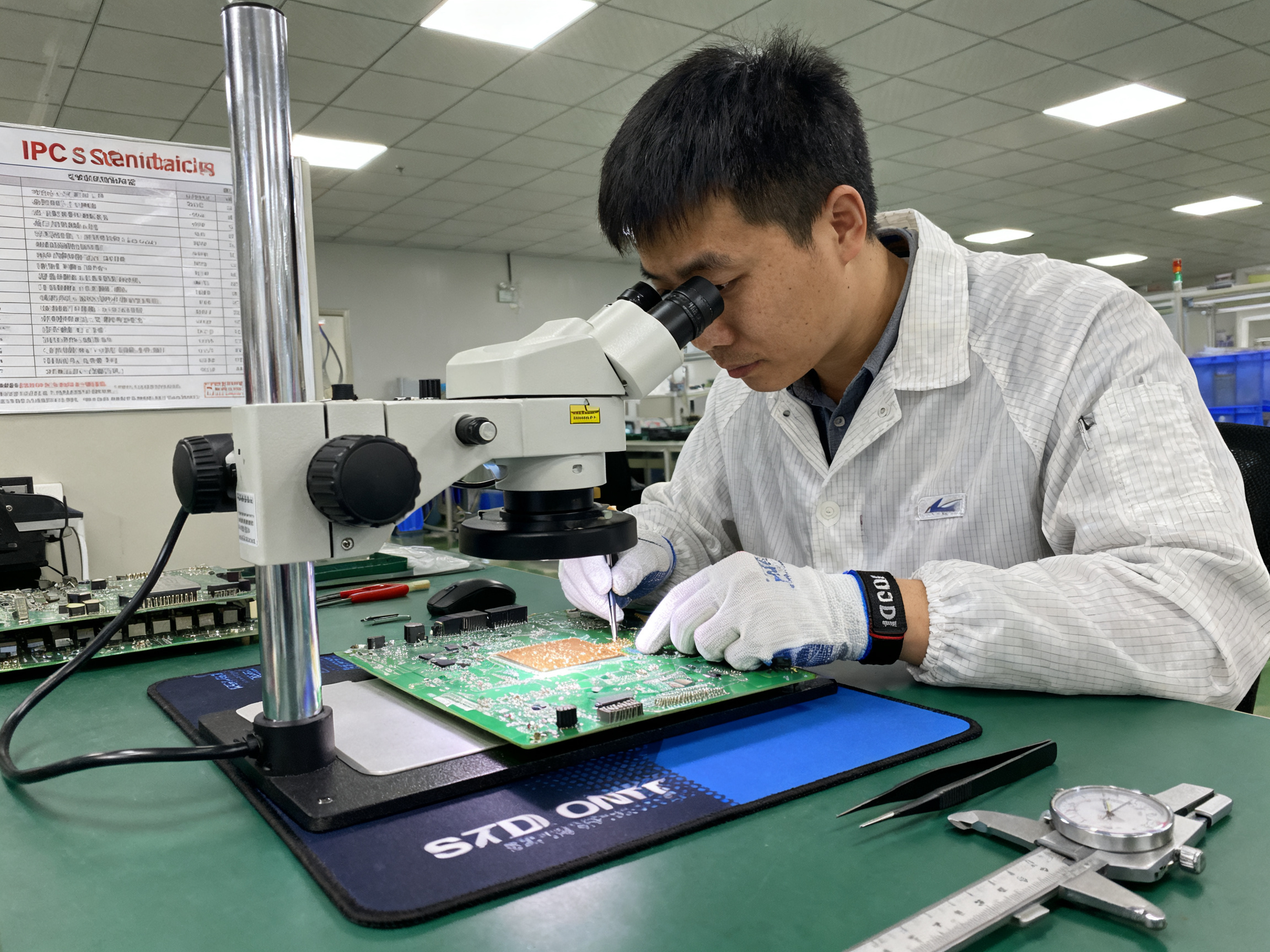
From Our Experience: How disciplined inspection and cleaning routines can reduce rework before defects reach final test.
What IPC standards say about cleanliness
IPC-A-610J covers visual acceptability of assembled boards. IPC J-STD-001J addresses soldering process and cleanliness requirements. Class 3 assemblies (aerospace, military) have the strictest cleanliness expectations. Failing an IPC inspection means rework, delays, and potential customer returns.
Daily workstation readiness checklist
- ESD mat tested and functional
- Magnification equipment clean and calibrated
- IPA wipes and brushes stocked
- Soldering tips clean and tinned
- Desiccant cabinet humidity within spec
- Component storage containers sealed
- Cleaning schedule documented
These seem like small things. They add up. Facilities that follow disciplined inspection and cleaning routines consistently report lower rework rates and better first-pass yield.
The inspection and cleaning gear category gets overlooked when manufacturers upgrade their SMT lines. But it’s where defects get caught before they cost you money. Shenzhen Chuxin Electronic Equipment Co., Ltd. builds inspection support into their SMT production lines for exactly this reason, helping manufacturers catch defects early rather than after reflow.
Buying Framework: Balancing Cost, Reliability, and SMT Line Compatibility
Here’s a scenario I’ve seen play out more than once. A small assembly shop buys a budget solder paste mixer to save money. Six months later, they’re dealing with inconsistent paste deposits, blaming the stencil. Then someone checks the mixing logs and realizes the “mixer” has no data logging at all. Nobody knows what actually happened.
That mixer technically worked. It mixed paste. But it created hidden costs that showed up as defects, rework, and frustrated operators.
Why low-cost tools work for prototypes but fail in production
For prototyping and low-volume work, basic tools often make sense. You’re building 50 boards, defects are catchable, and operator attention is high. A $50 soldering station and manual paste stirring might serve you fine.
But scale that to 10,000 boards per week, and the math changes fast. Operator fatigue sets in. Shift-to-shift variation becomes your enemy. Documentation requirements stack up. A mixer that needs 4 minutes of guesswork per batch, every batch, creates a bottleneck nobody tracks.
For military electronics, aerospace assemblies, and semiconductor packaging, the stakes climb higher. IPC standards require traceable processes. Auditors want calibration records and maintenance logs. A tool that can’t provide those records creates compliance risk that outweighs any purchase price savings.
What to document before you buy
Before signing any purchase order, lock down your actual requirements:
- Component types you’ll run (BGA, QFN, fine pitch) and their sensitivity
- Production volume targets and cycle time requirements
- Quality class (IPC Class 2 or 3) and any customer-specific requirements
- Compliance needs (RoHS, REACH, ITAR for defense work)
- Maintenance capacity and calibration schedule your team can support
- Integration requirements with existing SMT line controls and MES systems
Write these down. Share them with vendors. Ask how their equipment addresses each point.
Pro Insight: Recommended equipment upgrade sequence for manufacturers moving from legacy SMT tools to more controlled, lead-free-ready production.
Weighted scoring model for procurement teams
Use this framework to compare tools objectively:
| Evaluation Criteria | Weight | Prototyping | Production | Military/Aero |
|———————|——–|————-|————|—————-|
| Quality impact on defects | 25% | Medium | High | Critical |
| Ease of use and training time | 15% | High | Medium | Medium |
| Serviceability and spare parts | 15% | Low | High | High |
| Line compatibility and integration | 20% | Low | High | High |
| Documentation and traceability | 15% | Low | Medium | Critical |
| Total cost of ownership | 10% | Medium | High | High |
Score each option 1-5 on each criterion, multiply by weight, and sum the results. The tool with the highest score isn’t always the cheapest, but it should be the most defensible choice for your actual operation.
The goal isn’t buying the most expensive equipment. It’s buying the right tool for your production context and quality requirements.## Common Mistakes When Upgrading Electronics Assembly Gear
Let me tell you about a mistake I’ve seen more than once. A shop buys a cheap solder paste mixer to save money. Six months later, they keep blaming the stencil for inconsistent paste deposits. Nobody checked what the mixer was actually doing because it had no data logging at all.
That mixer technically worked. But it created hidden costs that showed up as defects, rework, and frustrated operators.
Here are the most common mistakes when upgrading assembly gear, and how to fix them:
| Mistake | What Goes Wrong | The Fix |
|———|—————–|———|
| Buying based on price alone | Cheap tools break fast, lack documentation, create compliance risk | Calculate total cost of ownership, not just purchase price |
| Ignoring operator training | Perfect equipment performs poorly in the wrong hands | Budget training time before going live with new tools |
| Skipping compatibility checks | Mixer doesn’t fit your paste jars, or station won’t work with your tips | Verify dimensions, connections, and consumable fit before ordering |
| Overlooking consumables | New station needs expensive proprietary tips you didn’t budget for | Include consumable costs in your purchase analysis |
| Inadequate ESD protection | Expensive ICs die from static damage nobody can trace | Require full ESD-safe workstation setup, not just a mat |
For solder paste mixers specifically, capacity mismatch causes problems. A small mixer can’t handle production batch sizes, so operators split batches and lose consistency. For soldering stations, poor temperature control defeats the purpose of having a “lead-free capable” tool. For multimeters, uncalibrated meters give false readings that send you chasing phantom problems.
From Our Experience: How disciplined inspection and cleaning routines can reduce rework before defects reach final test.
The corrective action mindset matters most: run pilot tests before full deployment, document your process windows, track defect data before and after upgrades, and standardize operator procedures so good results repeat across shifts.
Facilities that skip this step often end up with equipment that technically meets specs but fails to improve actual output. Shenzhen Chuxin Electronic Equipment Co., Ltd. recommends a phased upgrade approach, starting with pilot validation before committing to full line integration.
The goal isn’t buying the most expensive equipment. It’s buying tools that actually solve your specific problems, training your team to use them correctly, and tracking whether they deliver the improvements you expect.## Expert Recommendations for Building a Reliable Assembly Tool Set
Let’s bring this together into a clear action path. If you’re evaluating electronics assembly gear in 2026, here’s the priority order that makes the most sense:
1. Control solder paste consistency first. Research shows 60 to 70 percent of SMT defects trace back to paste printing problems. A reliable mixer with programmable settings and data logging eliminates operator variation and gives you traceable process records.
2. Stabilize soldering temperature. Temperature-controlled stations with PID control and fast thermal recovery handle lead-free work without creating cold joints or pad damage. Tip selection matters more than wattage.
3. Standardize wire prep. Gauge-matched strippers prevent nicked conductors that fail in the field. Test on scrap before production runs.
4. Choose safe measurement tools. CAT-rated multimeters with input protection keep operators safe and give accurate readings. Calibration records matter for compliance.
5. Strengthen inspection routines. Magnification, AOI, and X-ray for hidden joints catch defects before they cost you money. IPC-A-610J and IPC J-STD-001J define the acceptance criteria.
Pro Insight: Recommended equipment upgrade sequence for manufacturers moving from legacy SMT tools to more controlled, lead-free-ready production.
Role-specific next steps:
Production heads should pilot new equipment on a representative board run before full deployment. Track defect rates and first-pass yield before and after.
Procurement managers should calculate total cost of ownership, not just purchase price. Include maintenance, consumables, training, and downtime in the analysis.
Technical officers should verify vendor documentation supports your quality system requirements. Ask for calibration procedures, traceability output, and compliance certifications upfront.
Final Checklist: Building Your Assembly Tool Set
Required specifications to define:
- Component types and their sensitivity (BGA, QFN, fine pitch)
- Production volume and cycle time targets
- IPC quality class (Class 2 or Class 3)
- Compliance needs (RoHS, REACH, ITAR)
- Integration requirements with MES systems
Vendor questions to ask:
- What calibration and documentation does the equipment include?
- What are the warranty terms and spare parts lead times?
- How does the equipment integrate with existing line controls?
- What training and installation support is provided?
- Are consumables proprietary or standard?
Pilot test plan:
- Run 100 to 500 representative boards through the new equipment
- Document setup parameters and process window
- Track defect data, first-pass yield, and cycle time
- Compare results against baseline before full deployment
Training plan:
- Schedule operator training before equipment goes live
- Document standard operating procedures for each tool
- Verify competency through practical assessment
- Plan refresher training for new staff and process changes
Quality metrics to monitor:
- Defect rate in DPMO by process step
- First-pass yield percentage
- Rework and scrap rates
- Operator-to-operator variation
- Equipment uptime and mean time between failures
- Calibration status and out-of-tolerance events
Jace Liu works as an SMT equipment specialist at Shenzhen Chuxin Electronic Equipment Co., Ltd., handling overseas markets for reflow ovens and wave soldering machines. His background includes project management at Foxconn and specialized focus on SMT soldering solutions for EMS factory environments. The path to reliable assembly output comes down to matching your tools to your actual production requirements, training your team properly, and tracking whether the investment actually moves your defect numbers.