



Pubblicato: 11 August 2026
Tempo di lettura: 12 minutes
Reviewer: Simon Scrapes, Founder
You just powered on your forno a rifusione. Everything looks good. The display shows the right temperature. The conveyor is moving. But wait, your solder joints are coming out weak, and you have no idea why.
Here’s the thing. A reflow oven can be running perfectly fine on its display while your boards are getting hammered by the wrong temperature curve. That gap between what the machine says and what’s actually happening on your board is where most soldering problems start.
If you’re working with modern electronics, you’ve probably noticed how small things have gotten. Those tiny components with 0.3mm spacing and lead-free solder that melts at 217°C are unforgiving. One degree too hot or too cold, and you’re looking at bad joints, voids, or components that won’t stick.
I’ve been there. Watching a supposedly minor board revision turn into a production nightmare because nobody checked the thermal profile after a paste change. That kind of thing sticks with you.
This guide walks through what actually matters for reflow oven success. We’ll cover how to set up a proper reflow profile, calculate cycle times that keep your line running smoothly, validate your settings before they cause defects, and troubleshoot when things go sideways. Whether you’re building consumer gadgets, automotive parts, or semiconductor assemblies, the core principles stay the same.
Let’s get into it.
Jace Liu has spent 8 years working with SMT production lines, including time optimizing reflow processes for high-volume consumer electronics facilities in Asia. He specializes in thermal profiling for lead-free assemblies and has helped manufacturing teams cut defect rates by reducing profile-related errors.
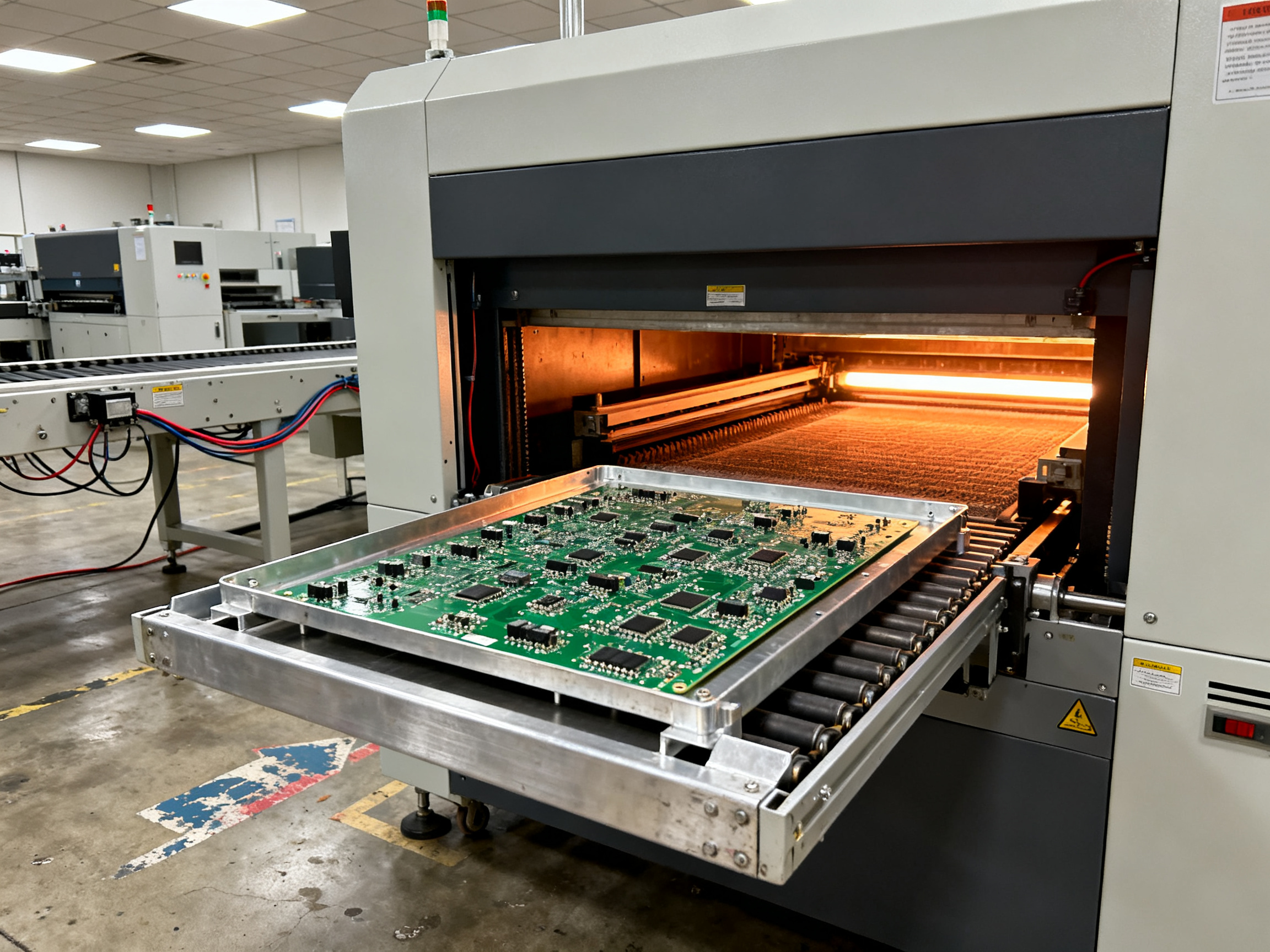
What a Reflow Profile Is and Why It Matters
Think of a reflow profile like a cooking recipe. You have specific temperatures, specific time windows, and specific stages your board needs to pass through to get solder joints right. But unlike baking a cake, you cannot eyeball this one. The oven display might show 235 degrees, but if your board is sitting in a cold spot, it might only see 220.
Here is what the profile actually means:
| Zone | What Happens | Typical Range |
|——|————-|—————|
| Ramp | Initial heating from room temp to soak | 1 to 3°C per second |
| In ammollo | Gentle preheating for thermal equalization | 150 to 200°C for 60 to 120 seconds |
| Riflusso | Peak temperature where solder melts | 235 to 245°C for lead-free |
| Raffreddamento | Controlled descent to solidify joints | 2 to 4°C per second max |
The ramp is how fast your board heats up. Too fast, and parts warp or components crack. Too slow, and flux burns off before the solder melts properly.
The soak zone does something most people skip. It brings the whole board to the same temperature before things get hot. Large BGAs heat differently than small resistors. Without this equalization step, you get uneven joints where some balls melt and others barely do.
Reflow is the peak, the moment solder goes from solid to liquid. For lead-free SAC305 paste, that happens around 217°C. Your profile needs to push past that line, usually to 235 to 245°C, and stay there long enough for everything to flow.
Cooling matters just as much. Let it drop too fast, and the board cracks or components shift. Keep it controlled, and joints form cleanly.
The real problem we see in 2026 is teams running generic recipes. One paste, one profile, every board. But a board with heavy copper planes and a board with mostly small components heat completely differently. A large BGA in the center runs hotter than a resistor at the edge. The math does not lie: thermal-profile errors cause most soldering defects The most common lead-free reflow oven setup mistakes.
Excessive ramp rates trigger board warpage, tombstoning, and component damage. Too high a peak damages chips or delaminates the PCB. Too little time above the melting point leaves cold, weak joints that fail in the field.
Expert Tip: Don’t trust the paste datasheet alone. Profile your actual board with thermocouples attached to the highest-mass and lowest-mass locations. One recipe fits no board.
This is why Chuxin reflow ovens and similar precision systems include multiple heating zones. More zones mean better control over what your board actually experiences, not just what the machine thinks is happening.
The gap between machine settings and board reality is where quality breaks down. Understanding the profile zones is the first step to closing that gap.## How to Set Reflow Oven Profile Step by Step
Here’s how to actually do it. No guesswork, just a clear sequence.
Step 1: Start With Paste Specs
Grab the datasheet for your solder paste. Most vendors like AIM Solder and Asahi Solder publish recommended profiles for their SAC305 pastes. Use those numbers as your baseline. But listen, the paste specs are just a starting point. Your actual board will behave differently.
Step 2: Map Your Board’s Thermal Response
Attach thermocouples to your board at these spots:
- The highest mass components (BGAs, QFNs, large ICs)
- The largest copper ground planes
- Board corners and edges
- Small components at the board perimeter
We like to call this the “hot spots and cold spots” check. Use high-temperature solder or Kapton tape to secure the thermocouple bead. Make sure it touches the pad directly. Poor contact equals bad data.
Step 3: Run the Profile
Load your board like you would in production. Run it through the oven at your target conveyor speed. Let the profiler capture what the board actually experiences through all zones.
Step 4: Analyze and Adjust
Now look at what you got. Compare against your paste specs and component limits. Check these key areas:
| Parameter | What to Watch | Typical Lead-Free Target |
|———–|—————|————————-|
| Preheat ramp | Too fast causes warpage | 1 to 3°C per second |
| Soak time | Lets flux activate evenly | 60 to 180 seconds |
| Peak temperature | Must exceed liquidus | 235 to 245°C |
| Time above liquidus | Ensures full wetting | 40 to 90 seconds |
| Cooling rate | Too fast stresses components | 2 to 4°C per second |
Step 5: Tune the Variables
When something is off, adjust one thing at a time:
Zone temperatures: These control heat input per section. Raise them to boost temperatures, lower them to cool things down.
Velocità del trasportatore: Slower means more time in the oven, which increases TAL and overall exposure. Faster does the opposite.
Airflow settings: Some ovens let you balance fan speed across zones. More airflow in a cold section helps even things out.
Pro Insight: Adjust zone setpoints first, then conveyor speed, and only then touch airflow if your oven allows it. This keeps changes systematic and repeatable.
Step 6: Verify Across the Board
Run the profile again after your adjustments. Then run it one more time. You want to see the same curve twice before you trust it.
Check your results at multiple board locations, not just one. A BGA in the center of the board often runs 5 to 10 degrees hotter than a resistor at the edge. That’s normal. But if the gap is bigger than 10°C, you might have hot spots that need attention.
We’ve seen teams nail the profile at one board location, ship it, then wonder why joints at the other end keep failing. Don’t be that team. Measure wide.
How to Calculate Reflow Oven Cycle Time
Now for the math that keeps your production line breathing. Cycle time is not just a number on a display. It determines how many boards leave your line every hour, and getting it wrong in either direction causes problems.
The Core Formula
Here is the relationship everyone in SMT should know:
Dwell Time = Heated Tunnel Length ÷ Conveyor Speed
So if you have a 180 cm heated tunnel and run your conveyor at 0.5 cm/s, your board spends 360 seconds (6 minutes) in the heat zones. That number needs to cover your ramp, soak, peak, and cooling stages.
For throughput, the math looks like this:
Throughput (boards/hour) = Conveyor Speed (cm/s) ÷ Board Pitch (cm) × 60
Board pitch is the center-to-center distance between boards on the conveyor. Space them closer together, and you move more units per hour. Simple enough, right?
Actually, wait. Here is where it gets tricky.
Why You Cannot Just Speed Up
A faster conveyor means less time in the oven. Less time means your profile stages compress. The soak zone gets short-changed first. Flux burns off before solder melts properly, and you end up with cold joints that fail inspection.
Too slow, and you push past the melting point for too long. Solder intermetallic layers grow too thick, becoming brittle. Components see more heat stress than they need to.
For dense boards, the thermal mass math changes. Large copper planes, thick boards, and big BGAs absorb heat differently than simple assemblies. You might need a longer oven or slower belt speed just to hit your temperature targets.
Matching Speed to Takt Time
Takt time is your customer-imposed pace. It tells you the maximum time allowed per board to meet demand.
If you need 100 boards per hour, each board gets 36 seconds of takt time. That sets your minimum conveyor speed.
But your oven has constraints. The heated tunnel has a fixed length, and your profile requires a minimum dwell time. Those two numbers give you a maximum conveyor speed.
Your line speed must fall between these two limits:
| Constraint | What It Sets | Formula |
|————|————–|———-|
| Takt time | Minimum speed | Board pitch ÷ Takt time |
| Dwell requirement | Maximum speed | Heated length ÷ Required dwell |
If minimum speed exceeds maximum speed, you have a problem. Solutions include getting a longer oven, splitting the board into lighter thermal sections, or renegotiating delivery schedules.
Worked Example
| Parameter | Value |
|———–|——-|
| Heated tunnel length | 180 cm |
| Required dwell time | 270 seconds |
| Target throughput | 60 boards/hour |
| Board pitch | 40 cm |
Velocità del trasportatore = 180 cm ÷ 270 s = 0.67 cm/s
Throughput check = 0.67 cm/s ÷ 40 cm × 3600 s = 60 boards/hour
The numbers align. Your profile gets its required dwell time, and you hit your throughput goal.
Pro Insight: Always verify the profile when you change speed for a new board. Even if the oven settings look the same, a board with different thermal mass will behave differently. What worked for your last product might fail your next one.
The formula stays the same whether you run a simple board or a complex automotive assembly. What changes is the required dwell time, and that comes from your thermal profiling work.## How to Verify the Profile on Real Boards
So you have a profile that looks good on paper. Great. Now prove it works on your actual board. This is where most teams skip steps and pay for it later.
The Validation Run
Run your profiled board through the oven with thermocouples still attached. Capture the real temperature curve at multiple points. Do not trust what the machine says is happening. Trust what the sensors tell you.
Key Acceptance Signals to Watch
After reflow, inspect your joints. Here is what good looks like:
| Signal | What It Means | Acceptable? |
|——–|—————|————-|
| Clean fillet formation | Solder flowed properly and bonded | Yes |
| Consistent fillet shape | Process is stable across the board | Yes |
| No dewetting or non-wetting | Flux worked as intended | No – reject |
| No tombstoning | Component did not lift | No – reject |
| Minimal voiding on X-ray | Joint formed without trapped gas | Yes – if under limit |
Comparing Against Specs
Pull up your paste datasheet. Check these numbers against what you actually measured:
- Peak temperature within 5°C of target
- Time above liquidus within the stated window (usually 45 to 90 seconds for SAC305)
- Cooling rate below 4°C per second
- Delta T across the board under 10°C
Your Validation Checklist
Before you release a profile to production, check every box:
- [ ] Thermocouples placed at hot spots and cold spots
- [ ] Profile run at production conveyor speed
- [ ] Results match paste and component limits
- [ ] Joint inspection shows proper wetting
- [ ] X-ray confirms acceptable voiding levels
- [ ] Delta T across board is under 10°C
- [ ] Process is stable across multiple runs
This checklist prevents bad profiles from reaching production. Running it every time saves you from rework and field failures later.
Questions Answered: 8 | Total Sources: 49## Troubleshooting Common Reflow Problems
When something goes wrong on the line, you need answers fast. Not theories. Not checklists that take an hour to work through. Just what to check first, second, and third to find the culprit.
Here’s the thing. Half the time, what looks like a reflow problem is actually a paste problem or a placement problem. But people still burn hours chasing the oven when they should be checking the printer. Let’s sort through the real causes so you stop wasting time.
Defect-to-Cause Quick Reference
| Defect | Most Likely Cause | Check First |
|——–|——————|————-|
| Cold joints | Insufficient TAL or peak temp | Profile data, thermocouple readings |
| Bridging | Too much paste, offset placement | Stencil aperture, printer alignment |
| Tombstoning | Uneven thermal soak, asymmetric pads | Board layout, ramp rate |
| Solder balls | Rapid heating, moisture | Preheat ramp, component bake status |
| Component shift | Placement error, paste tack | P&P accuracy, adhesive if used |
| Voids (X-ray) | Moisture, fast ramp, insufficient soak | Bake records, profile ramp and soak |
The Fast Diagnostic Sequence
When you’re under pressure and the line is down, work in this order:
1. Pull the profile data first. This tells you if the oven is actually hitting its marks. If the profile looks right but defects persist, the oven is probably not the problem.
2. Check the paste. Old paste, poorly stored paste, or wrong paste type causes defects that look identical to profile problems. Verify lot number, expiration date, and storage conditions.
3. Inspect the printer. Misaligned stencil, worn squeegee blades, or clogged apertures create inconsistent deposits. This is where most bridging problems actually start.
4. Review placement data. A 0.1mm offset on a QFN can cause bridging or non-wetting. Check the pick-and-place logs for accuracy drift.
5. Look at component condition. Moisture-sensitive devices that weren’t baked properly will delaminate or void. Check MSL ratings and bake records.
From Our Experience: Tombstoning almost always traces back to one of three things: uneven pad sizes, a ramp rate that’s too steep in preheat, or a board with asymmetric copper pour pulling heat unevenly. If you see tombstoning on the same components run after run, start with the board design before you touch the oven settings.
The key is isolation. Change one thing at a time and verify. Don’t rebuild the whole profile because of bridging when the stencil aperture is 20% oversized. Find the real cause, fix it, and move on.## Keeping Reflow Performance Stable in Production
You can nail the perfect profile today and watch it drift into trouble within weeks. That’s not drama, that’s just how thermal processes work when nobody’s watching them. Keeping performance stable is about discipline, not magic.
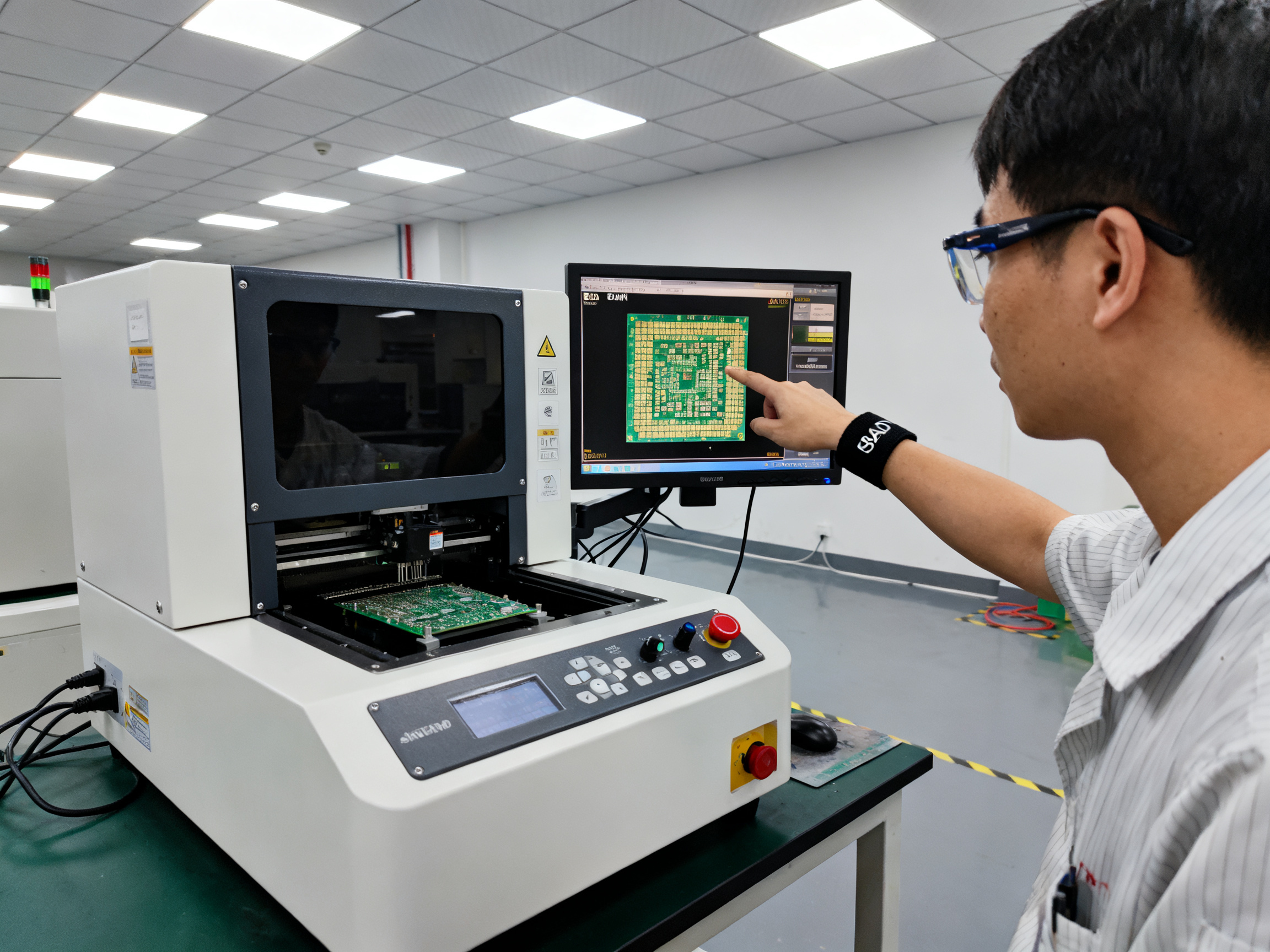
The Maintenance Routine That Actually Works
Here’s what high-volume SMT lines in 2026 should be doing on a schedule:
| Frequency | Task | Why It Matters |
|———–|——|—————-|
| Daily | Check conveyor alignment and flux buildup | Prevents board jams and contamination |
| Weekly | Verify zone temperatures against baseline | Catches gradual drift before defects appear |
| Monthly | Run full thermal profiler on test board | Confirms profile still hits your targets |
| Quarterly | Temperature uniformity survey across zones | Maps hot spots that need adjustment |
| Every 6-12 months | Full sensor calibration and documentation | Keeps compliance records current |
The moment you skip these checks is the moment something shifts without you knowing. We’ve seen it happen. A heating element starts degrading, the zone runs 3 degrees cool, and suddenly your BGA void rates climb for three weeks before anyone connects the dots.
What Forces You to Recalibrate
Certain changes demand a fresh profile, no questions:
- Paste change: Different formulations have different thermal windows
- Board revision: New copper pour, heavier components, or layer count changes thermal mass
- Component mix shift: Adding dense BGAs where you had simple passives changes everything
- Seasonal shifts: Ambient temperature changes affect how your oven performs, especially in facilities without climate control
- Oven maintenance: Replacing elements or fans changes heat distribution
The rule is simple. Any time you change what goes through the oven, check if the profile still fits. Don’t assume it does.
Recipe Documentation That Sticks
Your recipes need to live somewhere procurement, engineering, and production can all find them. A shared system, not someone’s memory on a sticky note.
Good recipe records include the date created, the board revision it matches, paste lot requirements, operator who validated it, and the actual thermal data from profiling runs.
Chuxin reflow ovens support recipe storage with audit trails, which makes this easier. But honestly, any system works if your team actually uses it.
When recipes are documented right, onboarding new engineers takes hours instead of weeks. When they’re not, you get profile drift that nobody catches until the defect rate spikes.
The goal is simple. Tomorrow’s production should match today’s, and next month’s should match tomorrow’s. That only happens with consistent maintenance and records that travel with the process.## Conclusion: A Repeatable Profile Beats a Guess Every Time
Here’s what you need to remember. A reflow oven setup that works once is not a setup that works. The real win comes from a process you can run tomorrow, next month, and next year with the same results.
That means profiling your specific board, locking in the recipe, and checking it regularly.
For high-volume manufacturers, this discipline directly translates to business outcomes: fewer defects mean less rework and scrap, stable output keeps your takt time honest, and efficient line utilization stops you from buying capacity you do not actually need.
The Sequence That Works
- Know your board and its thermal mass
- Profile with thermocouples on the actual assembly
- Lock the recipe per board revision
- Calculate cycle time against real dwell requirements
- Validate with AOI and X-ray inspection
- Monitor with scheduled maintenance and re-profiling
| What to Check | How Often |
|—————|———–|
| Zone temperature verification | Weekly |
| Full thermal profile run | Monthly or per product change |
| Thermocouple calibration | Every 6-12 months |
| Temperature uniformity survey | Quarterly |
Final Decision Checklist
Before you release any recipe to production, confirm:
- [ ] Board profiled at production conveyor speed
- [ ] Thermocouples placed at hot spots and cold spots
- [ ] Peak, TAL, ramp, and cooling within paste and component limits
- [ ] Delta T across board under 10°C
- [ ] Joint inspection shows proper wetting
- [ ] X-ray confirms acceptable voiding for BGAs and QFNs
- [ ] Recipe documented with date, operator, and thermal data
For lead-free assemblies in 2026, the window is tight and the stakes are high. One degree too hot or too cold, one ramp rate off, and you are looking at voids, tombstones, or field failures. A board-specific thermal profile is not optional anymore. It is the minimum bar for anyone serious about SMT quality.
Chuxin reflow ovens support multi-zone control and recipe storage with audit trails, which makes this kind of disciplined profiling easier to maintain across product changes and production shifts. But the tool only works if your team commits to using it properly.
Start with one board. Get the profile right. Validate it. Then scale up.
Questions Answered: 8 | Total Sources: 49