



PCB conveyor speed control is one of those deceptively simple knobs that can either stabilize an SMT line—or quietly turn small timing mismatches into chronic micro-stops.
A variable speed drive (VFD/VSD) gives you more control than a fixed-speed motor. But the real throughput gains don’t come from “running faster.” They come from SMT line balancing—keeping upstream and downstream stations from starving and blocking each other.
This guide shows how to use VFD-based speed control to improve flow while staying compatible with transfer rules like the SMEMA handshake.
Key takeaways
Conveyor speed is a line constraint, not a standalone optimization target.
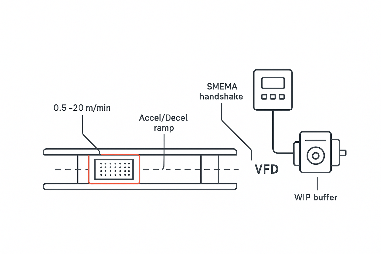
Use a VFD to control acceleration/deceleration ramps and steady-state speed—but respect transfer handshakes and sensors.
Line balance improves when you reduce starve/block cycles, not when you maximize one segment’s speed.
Your best “speed setting” is the one that keeps WIP predictable and minimizes transfer alarms.
Why conveyor speed is a line-balance problem (not a motor problem)
Most SMT lines don’t fail to hit throughput because a conveyor can’t run fast enough.
They fail because the line behaves like a chain: the slowest or most variable station determines the pace, and everything else oscillates between waiting (starved) and backing up (blocked).
Manncorp makes this point clearly in its discussion on scaling SMT lines: sustainable output comes from balancing the whole line rather than chasing the fastest single machine in isolation (see their overview on line balance and scaling SMT throughput).
So when you change conveyor speed, you’re really changing:
how quickly boards arrive at a station relative to its cycle time
how much WIP accumulates between stations
how often transfer logic pauses to prevent collisions
VFD conveyor speed control: what a drive actually changes
A VFD controls AC motor speed and torque by varying motor input frequency and voltage. Schneider Electric describes it this way: a VFD “varies and regulates motor input frequency, as well as voltage supply and current supply,” improving control over acceleration, speed changes, and deceleration (from Schneider Electric’s explanation of VFDs for conveyor motor applications (2020)).
Practically, for SMT board handling, a VFD gives you three levers that matter:
Steady-state transport speed (how quickly the board moves through a conveyor segment)
Acceleration/deceleration ramp (how gently you start/stop to avoid shock and slip)
Consistency under varying load (holding speed when friction, board weight, or belt condition changes)
A VFD can also act like a soft start—ramping the motor instead of snapping to full speed—reducing mechanical shock on belts, couplings, and gearboxes (see the plain-language VFD overview in E&I Sales’ VFD basics guide (2025)).
Pro Tip: If your conveyor “works fine” at constant speed but creates intermittent transfer faults during starts/stops, don’t change the final speed first—change the accel/decel ramp.
SMEMA handshake: why speed changes can create transfer faults
Speed control doesn’t exist in a vacuum. In a real line, transfers are gated by interface rules.
A common one is SMEMA (IPC‑9851), which uses a simple handshake: an upstream machine indicates a board is ready (Board Available) and a downstream machine indicates it can receive (Machine Ready). Transfer is allowed only when both conditions are true.
If you need a refresher on the signal meaning and handshake behavior, PCBSync’s overview of IPC‑9851 / SMEMA handshake signals (Machine Ready and Board Available) is a useful quick reference.
What this means for VFD tuning
When you increase conveyor speed without considering handshake timing and sensors, you can get:
boards arriving before downstream is truly ready
sensors missing short events (especially with marginal sensor placement or dirty reflectors)
“false availability” cycles that trigger micro-stops
In other words: you may run faster between stops, but you stop more often.
A practical tuning framework for PCB conveyor speed control
The goal is to make transfers boring:
predictable timing
stable spacing
minimal stop-start events
no board collisions or skew
Step 1: Define the constraint (where the line really sets pace)
Before touching speed, identify what limits output today:
a true bottleneck station (cycle time is longer than others)
variability (changeovers, feeder replenishment, false calls at AOI)
transfer instability (mis-transfer alarms, intermittent jams)
If you speed up conveyors upstream of a bottleneck, you typically just build WIP and increase block events.
Step 2: Choose a speed window—not a single number
Instead of one “optimal speed,” define an acceptable operating window:
minimum speed that avoids starving downstream
maximum speed that still transfers reliably (sensor + handshake + mechanics)
For reference, Chuxin SMT lists conveyor speed capability as “0.5–20 Meter/Min or specified by customer” for its inspection/single-track conveyor products (from the Chuxin SMT conveyor / inspection conveyor specifications).
That range tells you what the equipment can do—not what your line should do.
⚠️ Warning: Treat “max speed” as a mechanical capability, not a production target. Transfer stability is almost always the limiting factor.
Step 3: Tune ramps before chasing higher steady-state speed
Ramps matter because boards and belts are not perfectly rigid:
abrupt starts can slip belts or skew boards against rails
abrupt stops can cause “accordion” effects at board stops and buffers
A gentle ramp often reduces:
intermittent skew
board stop wear
occasional jams that show up only at shift changes or after maintenance
Step 4: Synchronize with upstream/downstream readiness (not just nominal takt)
Even if your theoretical takt time is stable, real lines have variability.
If your conveyor segment is feeding into:
a machine with frequent start/stop (AOI false calls, operator interventions)
a buffer with FIFO logic
a diverter or NG/OK path
…then speed changes should be validated against the worst-case stop-start conditions, not only average flow.
What to measure: throughput without self-deception
If you change speed and throughput doesn’t improve, it’s usually because you improved one metric while harming another.
Track these before/after (even with a simple log):
boards per hour at the end of line
stop count per hour (and stop duration)
starve time at bottleneck station
block time upstream of bottleneck
transfer alarms (mis-transfer, board not received, board not available)
WIP buffer level (average and max)
You don’t need perfect OEE math to learn something. You need consistent measurement.
Common failure modes (and what they often point to)
Symptom | What it often means | First adjustment to try |
|---|---|---|
Frequent micro-stops at transfers | handshake timing/sensor events not robust at higher speed | slow slightly; increase debounce/confirm sensor health; tune ramp |
Boards skew against rail guides | ramp too aggressive; belt slip; guide alignment issue | reduce accel; inspect belt tension; verify rail parallelism |
Jams increase after speed-up | spacing becomes unstable; downstream not ready; buffer logic triggers | cap max speed; add/adjust buffer rules; verify downstream readiness gating |
Throughput flat but WIP increases | you moved the bottleneck downstream | revert speed; address true bottleneck cycle time/variability |
More rejects/handling marks | mechanical shock at stops; board stop impact | soften decel; check stop mechanism and ESD belt condition |
For mechanical-related causes, it’s also worth reviewing board handling fundamentals like rail guide setup; Chuxin’s guide on PCB conveyor width adjustment and rail guide setup is a good baseline.
Where to use variable speed—and where not to
Use variable speed when you need to:
fine-tune board arrival timing to stabilize a bottleneck station
reduce stop-start shock through controlled ramps
support controlled buffering strategies (rather than uncontrolled queuing)
Avoid using speed as a “fix” when the real issue is:
chronic jamming due to mechanical alignment or board handling problems (see root causes and solutions for PCB conveyor jamming)
conveyor selection mismatch for high-speed lines (see jam-resistant PCB conveyor evaluation considerations)
downstream variability (AOI programming, changeover discipline, operator response time)
Next steps
If you want a faster line, the fastest path is usually not “turn the speed up.” It’s:
identify the true constraint
stabilize transfers (SMEMA + sensors + ramps)
widen the stable operating window
If you’re evaluating conveyor upgrades or retuning a line for a new product mix, S&M Co.Ltd can help you map speed windows, buffer strategy, and transfer interface requirements into a practical spec. Start with Chuxin SMT’s conveyor specifications and share your line layout and product mix so the tuning targets are grounded in reality.