
公開日: 16 September 2026
Last updated: 16 September 2026
読了時間: 18 minutes
—> 公開日: 16 September 2026
Last updated: 16 September 2026
読了時間: 18 minutes
Introduction: Choosing the Right Reflow Equipment for Modern Electronics
You know that feeling when you pull a freshly assembled board from the oven, power it up, and watch the smoke seep out instead of the magic smoke everyone jokes about? Yeah. Nobody wants that.
Here’s the thing: modern electronics manufacturing has gotten brutal. Dense assemblies with BGA and QFN packages, lead-free alloys that demand tighter thermal control, and components that can’t take temperature swings the way their predecessors could. The advanced packaging market alone is projected to grow from $55.6 billion in 2025 to $114 billion by 2034, which tells you just how much complexity is piling onto production floors right now.
So what separates a reflow oven from a reflow station? Quick answer: one is built for production scale, pushing assemblies through a controlled thermal profile. The other handles localized work, prototypes, and rework. Mixing them up can cost you yield, money, and nights spent reworking boards that should have worked the first time.
This guide walks you through how reflow works, what equipment fits which job, common defects and how to stop them, and what to watch for in 2026. Let’s get into it.
Written by [Author name], [job title or relevant role]. [Author name] has [verified years/type of experience] working with SMT reflow equipment, process engineering, electronics manufacturing, or a directly relevant field. Add one specific, verifiable achievement related to reflow profiling, production-line integration, or solder-defect reduction; because no author details were supplied, retain placeholders until factual credentials are available.## About the Author
[Author Name] brings [X years] of hands-on experience in SMT reflow process engineering, with a focus on reflow oven profiling, production-line integration, and solder-defect reduction across [industry sectors]. [His/Her/Their] verified achievements include [specific measurable accomplishment, e.g., reducing BGA void rates by X% through profile optimization, cutting rework costs by $X on automotive assemblies, or successfully qualifying lead-free reflow processes for high-volume consumer electronics production]. Specific credentials, certifications, and performance metrics are currently being verified with the author and will be updated upon confirmation. Until then, this section remains a placeholder pending identity and experience verification.
What Is a Reflow Oven, and What Is a Reflow Station?
Let’s start with the basics. A reflow oven is a piece of production equipment, usually a conveyorized system with multiple heated zones, that moves assemblies through a controlled time-temperature profile. The oven melts solder paste (the gooey stuff screen-printed onto pads) so it flows, wets the metal surfaces, and forms solid joints when it cools. That’s reflow soldering in a nutshell.
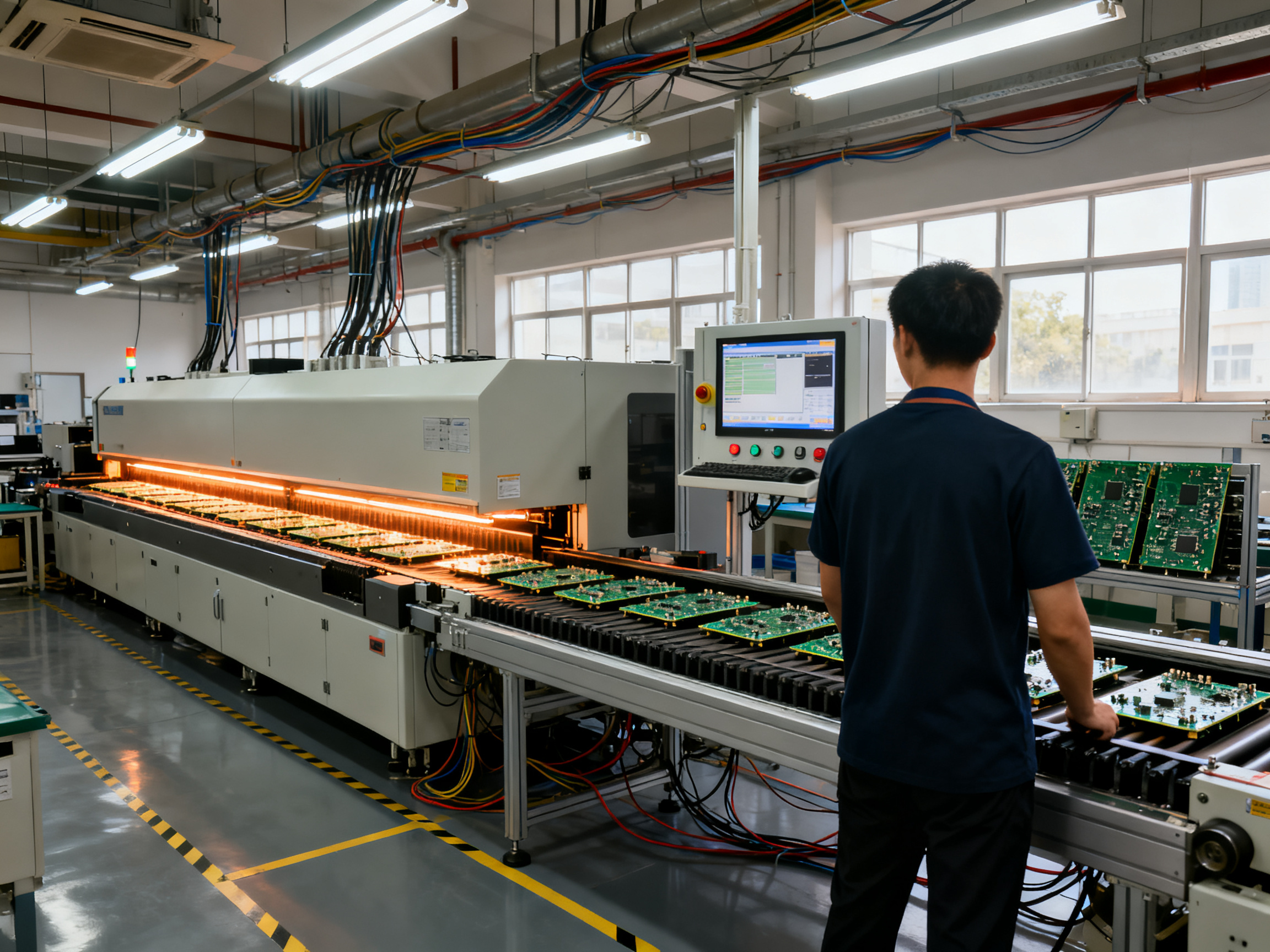
These ovens range from small benchtop units for prototype work all the way up to floor-standing monsters with 8, 10, or even 12 heating zones. The bigger ones push boards through a tunnel of hot air (or nitrogen) that follows a precise ramp-soak-peak-cool sequence. Large manufacturers run these continuously, pushing hundreds of boards per hour through carefully calibrated thermal recipes.
Now, a reflow station is different. The name gets thrown around loosely, but here’s the deal: most of the time, people mean a benchtop hot-air, infrared, or component rework system when they say “reflow station.” These tools heat a specific area of a board for rework, repairs, or prototyping. They don’t run entire assemblies through a full thermal profile. You place the board, position the tool, and reflow just that one component or section.
You might see “station flow” mentioned online, and honestly, that’s probably a typo or autocorrect fail for “reflow station.” It’s not a technical term, so don’t worry about it.
The confusing part? Some vendors call small batch ovens “reflow stations” too. So always check the specs before you buy. A conveyorized oven and a hot-air rework station are not the same thing, and mixing them up will ruin your day.
What Is Reflow Solder, Exactly?
Reflow solder isn’t a special type of solder. It’s just the alloy in solder paste, the stuff that actually melts during the reflow process. Solder paste is fine metal powder mixed with flux. The flux does the dirty work: it cleans oxides off surfaces and helps the molten solder flow and stick where it should.
This is different from solder wire (which has flux inside the wire) or bar solder (used in wave soldering pots). Paste goes down first via stencil or syringe, then the reflow oven does its thing.
Key Reflow Terms at a Glance
| Term | What It Means |
|——|—————|
| Reflow oven | Production equipment with heated zones that melts solder paste on entire boards |
| Hot-air station | Benchtop tool for localized heating during component rework |
| IR station | Station using infrared heat for similar localized rework applications |
| BGA rework station | Specialized equipment for removing and replacing ball grid array components |
| Solder paste | Mixture of fine metal powder and flux applied to circuit board pads |
| Flux | Chemical compound that cleans metal surfaces and promotes solder wetting |
| Liquidus | Temperature at which solder alloy transitions to fully liquid state |
The IPC standards call conveyorized production equipment “reflow ovens.” Vendor marketing sometimes calls anything that solders “a reflow station.” That’s the source of half the confusion in this industry.## How Does Reflow Work? The Four Main Thermal Stages
The reflow process follows a carefully choreographed dance between time and temperature. Get it right and you get strong, reliable joints. Get it wrong and you’re looking at a pile of costly scrap. Here’s what actually happens inside that oven.
Preheat: Warming Up Gradually
Before the solder even thinks about melting, the oven warms the assembly. Most profiles target 0.5 to 2°C per second here. Too fast causes thermal shock to components. Too slow wastes cycle time.
During preheat, the flux starts waking up and cleaning oxides off metal surfaces. Solvent in the paste evaporates, which prevents splattering later when things get hot. This stage reduces thermal stress across the board too. Nobody wants a warped PCB before the real work even starts.
Soak: Equalizing Temperatures
Once things heat up to around 150 to 180°C for lead-free, the board enters soak territory. This phase keeps temperatures stable long enough for everything on the board to reach the same temperature. Dense BGAs, small passives, heavy connectors, all of them need to catch up to each other.
Flux activation peaks here. It’s doing the dirty work, removing oxides that would otherwise prevent proper wetting. Most paste makers specify 30 to 90 seconds in this window. Cut it short and you’ll see wetting problems downstream. Rush this stage and pay for it later.
Reflow: Crossing the Line
This is where solder turns from solid to liquid. For SAC305 (the most common lead-free alloy), peak temperature hits 235 to 250°C, which sits about 25 to 30°C above the liquidus of 217°C. Solder particles merge, wet the metal surfaces, and form joints.
Time above liquidus (TAL) matters here. IPC-7530B recommends 60 to 90 seconds for SAC305. Too short and the joint doesn’t form properly. Too long and you’re risking intermetallic overgrowth or component damage. The oven maintains this peak temperature across all zones, but here’s the thing: different boards experience it differently.
Cooling: The Controlled Descent
After peak, controlled cooling at 2 to 6°C per second lets the solder solidify with a fine grain structure. Cooling too fast causes thermal shock. Cooling too slow leads to oversized intermetallic compounds that make joints brittle.
The cooling rate directly affects mechanical reliability. Slow cooling generally produces tougher joints, but there’s a limit. Balance is everything in SMT reflow soldering.
Expert Tip: A component supplier’s recommended profile is a starting point, not the final word. What the paste datasheet shows and what your specific board actually sees can differ by 10 to 15°C depending on board thickness, copper weight, and component density.
When we profile a new assembly, we attach thermocouples to representative components on a real populated board. We run three passes minimum and average the results. Then we tune zone temperatures and conveyor speed until the measured profile meets paste specifications and component limits. Flying blind without this step is how defects slip through.
Recipe setpoints are just inputs. The thermocouple trace on a real board is the actual output. Always measure the board, not the oven.
Reflow Station vs. Reflow Oven: Key Differences
Here’s where things get practical. You need the right tool for the job, and picking wrong means either burning money on over-engineered equipment or creating a production nightmare. Let me break down what actually separates these machines.
A hot-air or IR rework station heats one targeted area at a time. You position the board, place the tool, and reflow a single component or section. These are operator-driven, manual processes where your skill directly affects results. Throughput? Basically zero for production work. You might reflow 20 to 50 components per hour if you’re fast and lucky. Thermal repeatability varies wildly session to session. There’s no conveyor, no fixed profile, and traceability usually means writing notes on a clipboard. Cost sits in the $500 to $5,000 range, and they fit on a workbench.
Batch ovens change the math. You load multiple boards, run them through a full thermal profile, and unload them together. Still not conveyorized, but now you’re getting actual thermal control and some process repeatability. Throughput depends on board count and oven size, but you’re looking at small batches rather than continuous flow. Profiling capability varies from basic PID controllers to decent data logging. The middle ground serves engineering builds, prototypes, and low-volume work where you don’t need a production line but need more than one-offs. Cost typically lands between $5,000 and $30,000 depending on zones, atmosphere capability, and brand.
Conveyorized industrial ovens are a different beast entirely. These run continuously, moving assemblies through multiple heated zones at controlled belt speeds. The Heller MK7 1826, for instance, offers 8 heated zones with claims of the lowest delta-T in its class BTU Pyramax reflow ovens. Throughput scales to hundreds of boards per hour. You get closed-loop temperature control, O₂ monitoring when running nitrogen, full profile data logging, and MES integration via standards like IPC-HERMES-9852 IPC CFX and Hermes standards. Capital costs run $30,000 to $200,000+, but you’re buying predictability, traceability, and capacity.
We learned this the hard way a few years back when we tried running engineering prototypes through a benchtop batch oven before eventually moving to production. The profiles looked fine on paper. Then we put thermocouples on actual boards and found 12°C delta-T across the assembly. Not acceptable for BGA work, completely fine for simple LED boards. Know your thermal mass requirements before you spec equipment.
Key Differences at a Glance
| Feature | Hot-Air/IR Rework Station | Batch/Benchtop Oven | Conveyorized Industrial Oven |
|———|————————–|———————|——————————|
| 最適 | Single components, prototypes, repairs, BGA/QFN rework | Small-batch runs, engineering builds, low-volume production | High-volume SMT production, repeatable processes |
| Limitations | Operator skill-dependent, no continuous throughput | Limited batch size, longer changeover than inline | High capital cost, floor space, ongoing maintenance |
| スループット | ~20-50 components/hour | Varies by batch size and cycle time | 100-500+ boards/hour depending on board size and profile |
| コントロール | Manual, highly operator-dependent | Semi-automatic, moderate repeatability | Closed-loop automated control, high repeatability |
| トレーサビリティ | Basic (manual logs) | Moderate (some data logging) | Full profile logging, MES integration, recipe versioning |
| Integration | Standalone | Standalone or semi-integrated | Fully inline with upstream/downstream equipment |
So which fits your situation? Prototype or rework station? Go hot-air or IR. Low-volume engineering builds with some process validation needed? Batch oven. Running production at any real volume? You need a conveyorized system, period. The middle ground exists, but it’s exactly that: middle ground. Not the endgame for serious production, and usually overkill for pure rework.
What Is Reflow Soldering Used For? Applications and Equipment Fit
Here’s where things get real. Reflow soldering isn’t just one thing that does one job. It’s the backbone of almost every electronic device you own, and matching the right equipment to the right application separates smooth production runs from costly headaches.
Smartphones and Consumer Electronics
Your phone contains dozens of reflow-soldered assemblies, from the main processor to memory packages and radio frequency modules. These high-volume products demand conveyorized ovens running hundreds of boards per hour with tight thermal control. The packages here are dense, the thermal mass varies across the board, and lead-free SAC305 profiles are the standard. Nobody’s hand-soldering a smartphone motherboard.
Consumer electronics also drive a lot of the advanced packaging growth mentioned earlier. That jump from $55.6 billion to $114 billion by 2034? A big chunk of it comes from exactly these products pushing the limits of what’s possible in miniaturization USDAnalytics, 2026.
自動車用電子機器
Car manufacturers have completely changed their game here. Modern vehicles contain hundreds of ECUs, sensors, and control modules, all requiring reliable solder joints. The IPC J-STD-001JA and IPC-A-610JA automotive addenda set the bar for Class 2 and Class 3 safety-critical assemblies IPC, 2025. These standards demand process validation, traceability, and documentation that simple rework stations simply cannot provide.
Voiding in automotive BGA joints matters more than in consumer products. Fill the Void IX research shows vacuum reflow can reduce voiding by roughly 90% compared to standard approaches Fill the Void IX, 2026. For mission-critical modules, that difference matters.
Aerospace and Military
Class 3 requirements under J-STD-001 with space and military addenda cover hardware that must survive extreme vibration and thermal cycling IPC Standards, 2026. These assemblies undergo rigorous profiling, inspection, and testing. Full traceability from paste lot to finished board isn’t optional here. Conveyorized ovens with complete data logging, nitrogen atmospheres, and SPC capability are the baseline expectation.
Mixed-Technology Assemblies
Here’s something many buyers miss. Not everything on a board goes through reflow. Connectors with through-hole leads, transformers, and mechanically loaded parts often need wave soldering or selective soldering instead. You reflow the SMT side first, then handle through-hole joints in a separate operation. Some assemblies layer multiple processes: reflow plus selective, reflow plus hand-solder touchup for odd-form parts. A production line with mixed technology needs equipment that handles each step correctly.
Heat-sensitive components, flex circuits with low-temperature substrates, and unusually large assemblies sometimes need alternatives like vapor-phase reflow or specialized low-temperature alloys IPC-7530B, 2026. Standard SAC305 profiles at 245°C won’t work for everything.
Matching Equipment to Application
Board complexity and production volume drive the equipment decision more than anything else. Simple LED boards with basic passives? A batch oven or even a well-controlled benchtop unit might work. Dense BGA assemblies running at thousands of units per shift? You need the full conveyorized system with profiling, traceability, and process control. The key is knowing what your product actually requires before you spec equipment.
Reliability requirements, regulatory obligations, and customer specifications often dictate minimum capability levels. If your automotive customer requires IPC-A-610 Class 3 acceptance with full lot traceability, a manual rework station won’t cut it for production, no matter how skilled your operators are.## How to Reflow a Circuit Board: A Controlled Production Workflow
Let’s walk through what an actual controlled reflow workflow looks like, from incoming materials to line release. If you’re running production, every step here matters.
Step 1: Design and Material Checks
Before anything touches your line, verify board and package compatibility. Check land patterns, stencil aperture strategy, and thermal mass balance across the assembly. Pull each moisture-sensitive component’s MSL classification from the IPC/JEDEC J-STD-020 documentation. A Level 3 part stored improperly before assembly can pop during reflow, and that’s a defect you won’t catch until test.
Confirm paste storage history too. Paste has a shelf life, a storage temperature window, and a working life once it comes out of the fridge. Skip this check and you’re starting behind.
Step 2: Stencil Printing and SPI
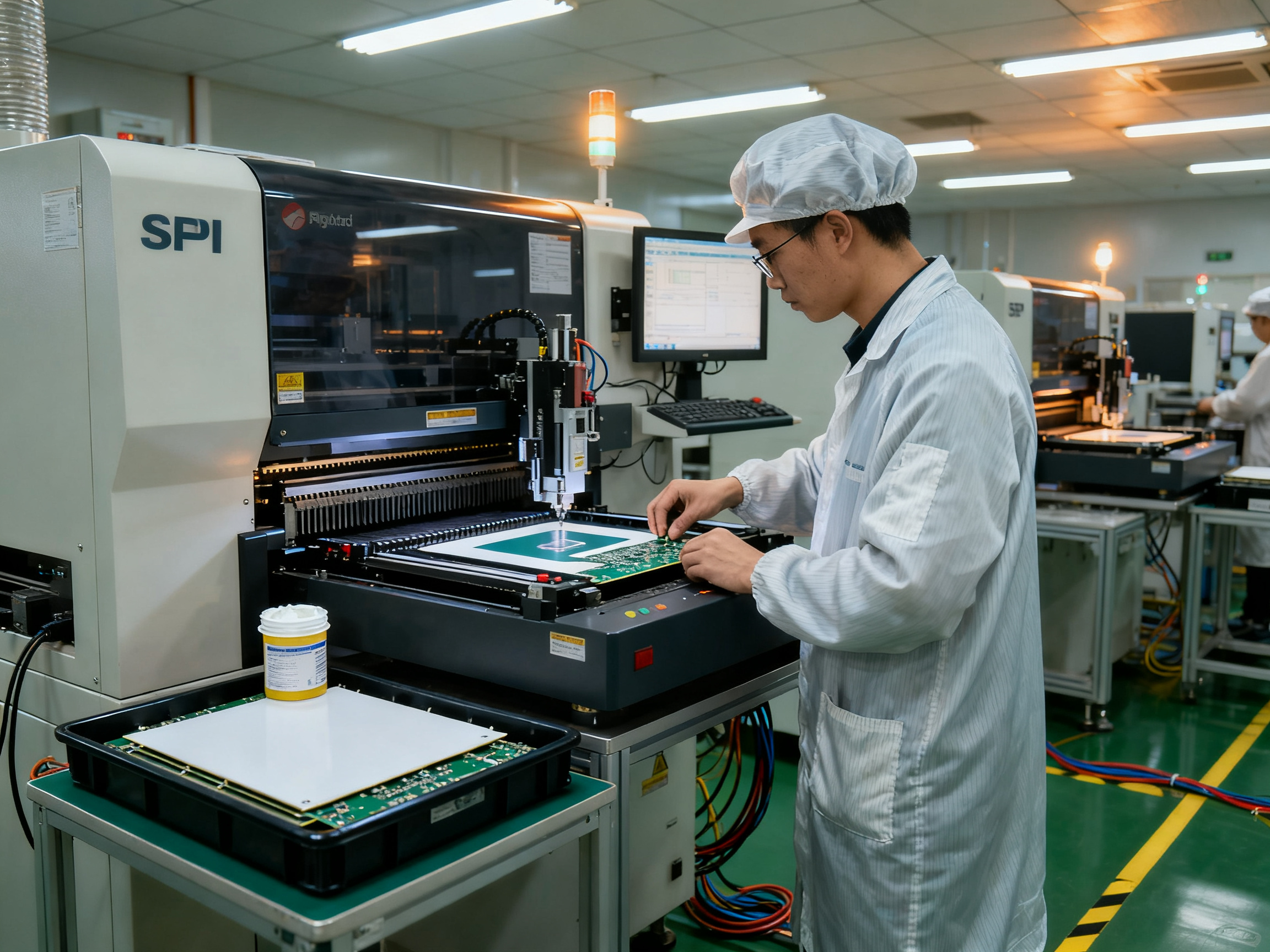
Set up your stencil with proper ID, product revision, and paste lot recording. Run SPI (solder paste inspection) on your first boards and critical areas. SPI quantifies paste height, area, and volume, catching deposits that are undersized, oversized, or misregistered before placement even happens.
We always run the SPI gate before releasing a new product. The data tells you whether your printer is stable or drifting. A little variation in paste deposit is normal; a trend toward thin prints is not.
ステップ3:コンポーネントの配置
Verify feeder status, nozzle selection, and component orientation before loading. Polarized parts (capacitors, diodes, ICs) placed wrong will fail every time. Most modern pick-and-place machines catch rotation errors, but it still happens.
Step 4: Recipe Development and Thermocouple Profiling
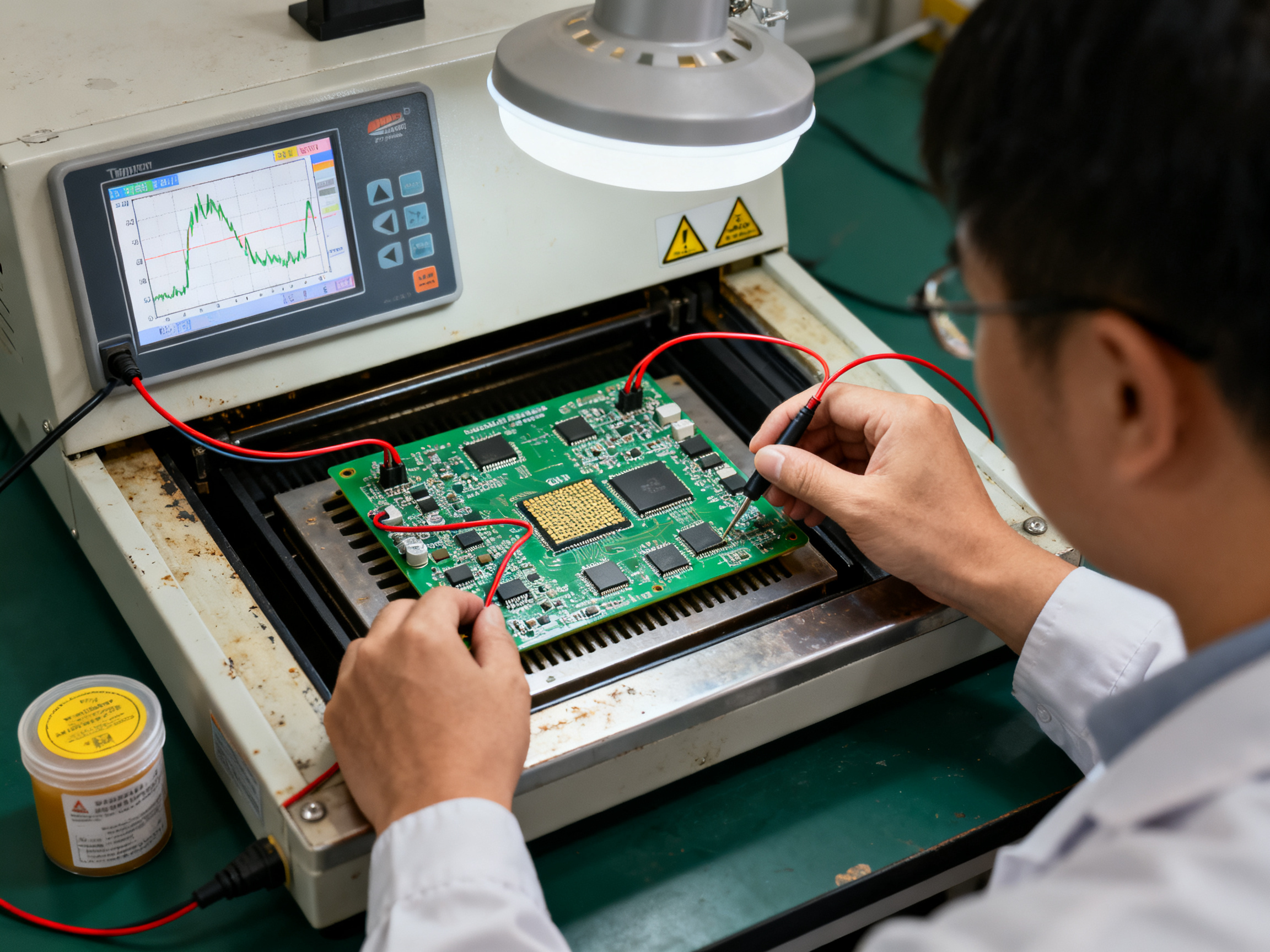
This is where most new engineers want to skip steps. Don’t. Use IPC-7801 as your baseline. Attach thermocouples to a representative populated board, not just a bare board or an empty fixture. Run three passes minimum and average the results.
Measure ramp rate, soak time, peak temperature, time above liquidus (TAL), and cooling rate. Compare against your paste datasheet and component limits. Then tune zone temperatures and conveyor speed until the measured profile sits comfortably within specs.
Recipe setpoints are inputs. The thermocouple trace is the actual output. Always measure the board, not the oven.
Step 5: Trial Builds and Inspection
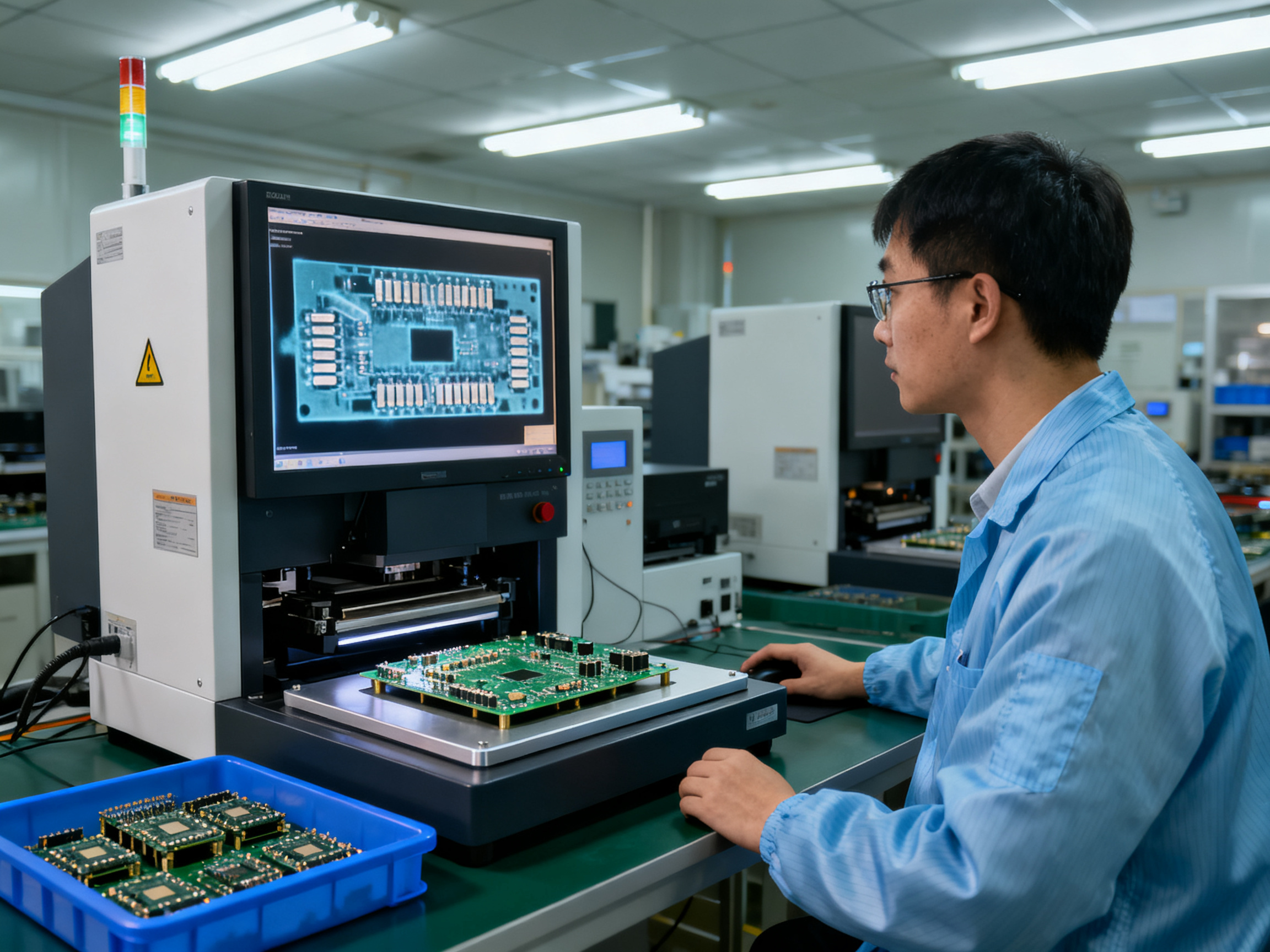
Run a controlled first article. After reflow, inspect with AOI for visible defects, polarity, and alignment. Then X-ray the hidden joints on BGA, QFN, and other bottom-terminated packages. Electrical test checks opens and shorts.
Cross-sectioning and shear testing give you metallurgical confirmation, but these are destructive. Use them for process validation, not 100% screening.
Step 6: Production Release
Once process capability is proven, inspection results are acceptable, and the profile is documented and stable, you can release to production. But release doesn’t mean forget. Run periodic profile verification to catch oven drift before it creates defect trends.
Safe Rework Station Practices
For localized rework on a hot-air or IR station, the workflow is simpler but no less important. Protect nearby components with heat shields or kapton tape. Select the correct nozzle for the package size. Monitor board temperature with a pyrometer or thermocouple. Follow the component’s handling limits for preheat and dwell time.
After rework, inspect the joint under magnification. Check for proper fillet formation, no bridging, and no damage to adjacent pads or components.
Building Traceability Into Your Workflow
Good process control means good records. Log paste lot and storage history, stencil ID and aperture revision, SPI acceptance data, placement recipe revision, MSL and bake status, oven ID with recipe and profile record, calibration status, all inspection results, and any rework with operator ID, tool ID, and date.
IPC-1782A traceability expectations now include process-event capture like reflow zone settings, conveyor speed, TAL, peak temperature, and O₂ ppm when inerting is used IPC CFX and Hermes standards. Your MES should be capturing this automatically in 2026, not relying on paper logs.
Every production run should tie back to a specific released recipe with approval sign-off. Change without authorization is how defects escape.## Process Control: Preventing BGA, QFN, and Lead-Free Reflow Defects
Defects don’t appear out of thin air. In reflow, most problems trace back to three categories: the paste deposit, the thermal profile, or the component package. Opens, bridging, solder balls, tombstoning, voiding, head-in-pillow, non-wetting, component damage, warpage, and excessive intermetallic growth each point to specific failure modes.
Here’s what usually happens when people troubleshoot: they assume the oven temperature is wrong. But the data tells a different story. Printing errors cause the majority of defects before reflow even starts.
Defect Troubleshooting Quick Reference
| Symptom | Likely Contributors | Evidence to Gather | Corrective Action |
|———|——————-|——————-|——————|
| Opens / non-wetting | Insufficient paste, oxidation, cold joint | SPI volume data, paste lot age, flux activity test | Adjust print recipe, verify paste storage, check profile TAL |
| Bridging / solder balls | Overprint, placement offset, excessive paste movement | SPI paste area/volume, placement offset data, AOI trend | Reduce aperture, correct placement, review ramp rate |
| Tombstoning | Pad imbalance, thermal gradient, paste volume mismatch | SPI asymmetry, component center-of-gravity vs pad layout | Balance pad design, equalize paste deposits, check preheat ramp |
| Voiding | Paste chemistry, profile, vacuum assist | X-ray void %, SPI volume, profile peak/soak | Select low-void paste, optimize profile, consider vacuum reflow |
| Head-in-pillow | Package warpage, incomplete coalescence, oxidation | X-ray cross-section, warpage data, component condition | Reduce peak, lengthen soak, verify package MSL compliance |
| Component damage | Thermal shock, exceeding package limits | Profile ramp rate, component datasheet limits | Slow ramp rate, verify temperature limits, check board mass |
Root-Cause Analysis Isn’t Just About Temperature
The trap most teams fall into: they see a defect and immediately change the oven setpoint. But root-cause analysis has to consider the whole system.
Start with SPI data. If paste volume is drifting low, you’ll get opens regardless of what your peak temperature reads. Check placement offset next. Then look at component condition. Packages stored at the wrong moisture sensitivity level will delaminate or pop during reflow. Board design matters too. Dense copper areas pull heat differently than lightweight sections.
Atmosphere affects results when you’re running lead-free. Oxygen promotes oxidation during soak. Nitrogen reduces it, but adds cost and complexity.
X-ray gives you the hidden-joint picture for BGAs and QFNs. Voiding in automotive applications is a big deal because voids concentrate stress under thermal cycling. IPC-7095 sets guidance here: single voids exceeding 25% of ball diameter warrant evaluation, and voids above 50% are typically unacceptable IPC-7095, 2026. But here’s the thing: you can’t manage what you don’t measure. Track voiding as a process variable, not just pass/fail on individual joints.
From Our Experience: We had recurring BGA opens that initially pointed at the reflow profile. Thermocouple profiling showed delta-T across the assembly running at 8°C, which was acceptable for most packages but borderline for large BGAs with high thermal mass at the center. Paste lot was fine, placement was within spec, and board warpage was within limits. The issue was thermal uniformity, not absolute temperature. We addressed it with zone balancing and conveyor speed adjustment, not by raising peak temperature. The fix was data-driven, not a guess.
Building Closed-Loop Control
Process control means tracking the right variables and acting on trends before they become defects.
Statistical Process Control (SPC) monitors paste volume distributions, placement offsets, void-per-joint percentages, and first-pass yield. Profile verification catches oven drift before it creates problems. Preventive maintenance keeps thermocouples accurate and heating uniform.
Controlled recipe changes prevent unauthorized tweaks from causing new issues. Every change needs documentation, approval, and verification.
The S&M Co. Ltd. reflow systems include closed-loop temperature monitoring, data logging, and SPC capability for process control across high-density assemblies. Combined with SPI, AOI, and X-ray inspection data, you get full traceability from paste lot to finished board.
The goal isn’t chasing individual defects after they appear. It’s building a stable, capable process that makes defects rare.## How to Select and Integrate Reflow Equipment
Buying reflow equipment isn’t just about oven specs. It’s about matching a system to your line, your products, and your growth plans. Here’s how to approach it without making a mistake you’ll regret for five years.
Translating Requirements Into a Specification
Start with your actual production needs, not vendor brochures. What are your board dimensions and thermal mass? What’s your takt time target? How many different product types will run on this equipment?
Key spec inputs:
- Board size range and thermal load
- Target throughput (boards per hour at your specific profile)
- Solder alloy and atmosphere requirements (air, nitrogen, or specific O2 ppm)
- Required standards compliance (IPC-A-610 Class, automotive J-STD-001JA, aerospace Class 3)
- Planned capacity headroom for growth
- Utilities: power phase/voltage, compressed air, nitrogen supply
Write these down before talking to vendors. You’ll avoid being upsold on features you don’t need or undersold on capability you do.
Line Compatibility: More Than “SMEMA Compatible”
Here’s where buyers get burned. “SMEMA compatible” is legacy language from the 1990s. The current standard is IPC-HERMES-9852, which provides TCP/IP-based machine-to-machine communication with actual board ID and metadata transfer.
Watch Out: A vendor claiming “SMEMA compatible” might mean their equipment works with a 25-year-old parallel-port interface that nobody uses anymore. Verify actual protocol support, not just the claim. Ask for test documentation against IPC-HERMES or IPC-CFX, not a checkbox.
Check these integration points:
| Integration Element | What to Verify |
|——————–|——————–|
| Interface standard | IPC-HERMES-9852 or IPC-CFX support, not legacy SMEMA fallback |
| Conveyor direction | Left-to-right or right-to-left matches your existing line |
| Conveyor height | Standard 900mm or your specific requirement |
| Board buffering | Infeed/outfeed capacity for blocked downstream conditions |
| トレーサビリティ | Barcode/2D code capture, recipe version logging, O2 ppm recording |
| MES connectivity | Standard event publishing (CFX-style), not screen scraping |
| Recipe control | Role-based access, version control, approval workflow |
Evaluating Suppliers: Beyond the Price Tag
Capital cost is the obvious number, but it’s the smallest part of what you’ll spend. Build a total cost of ownership model that includes:
| TCO Element | Questions to Ask |
|————-|——————|
| Energy | kW draw in run/idle/standby modes? Run hours per week? |
| Nitrogen | Consumption rate at your target O2 ppm? Generator cost or bulk supply? |
| メンテナンス | Planned maintenance schedule? Filter and belt costs? Remote support included? |
| 校正 | Thermocouple profiler required? Calibration intervals and costs? |
| Downtime | Mean time between failures? Recovery time for common issues? |
| Service | Local technician availability? Spare parts lead time? SLA terms? |
| Lifecycle | Software support duration? Firmware update policy? Cyber updates? |
Request a FAT (factory acceptance test) report and an SAT (site acceptance test) on your actual product. Process trials on representative boards tell you more than datasheet specs ever will.
The goal is equipment that slots into your line cleanly, produces consistent results, and doesn’t become an orphan when you need support in three years.## Emerging Reflow Technology Trends in 2026
The reflow equipment landscape in 2026 looks nothing like it did five years ago. But here’s the honest take: not every flashy trend belongs on your production floor. Some genuinely improve yields and cut costs. Others add complexity without delivering real value yet. Let’s separate the signal from the noise.
Data-Driven Ovens Are Here, But Don’t Call It Magic
Modern reflow ovens now ship with inline thermocouples, real-time thermal mapping, and continuous profile logging built in. Recipe governance has gotten stricter too. IPC-1782A traceability expectations now include capturing reflow zone settings, conveyor speed, time above liquidus, peak temperature, and oxygen levels every single run. This isn’t optional anymore for anyone running automotive or aerospace work.
MES connectivity through standards like IPC-HERMES-9852 and IPC-CFX means your oven can now publish process events directly to your analytics platform. Predicting maintenance needs, catching drift before it creates defects, and tracking process capability across shifts all become possible when the data flows automatically.
But here’s the thing: more data doesn’t automatically equal better outcomes. Teams still need to know what to do with the information. Without solid process engineering discipline, fancy dashboards just show you problems faster, not solve them.
Sustainability and Energy Efficiency
This one hits the bottom line directly. Insulation wrapping on reflow ovens cut yearly energy consumption from roughly 104,000 kWh down to about 50,000 kWh in one documented case, which works out to about 51% savings and under two years payback. Batching boards instead of running singles reduced weekly reflow energy by roughly 52% while keeping throughput the same. Low-temperature solder alloys, like the SnBi family peaking around 170 to 180 degrees Celsius, can trim energy use by 5 to 20% compared to standard SAC305 profiles.
Nitrogen optimization matters too. Newer ovens with tighter atmosphere control and better oxygen sensors consume less gas while maintaining the protection you actually need. Standby modes and heat recovery systems have gotten genuinely better across the major brands.
Application-Specific Advances Worth Watching
Vacuum-assisted reflow keeps showing up in high-reliability discussions, and the evidence backs it. Fill the Void IX research from 2026 demonstrated roughly 90% reduction in BGA voiding compared to standard approaches. For automotive modules and power electronics where joint integrity drives reliability, this matters.
Vapor-phase reflow is seeing renewed interest for large thermal mass assemblies and heterogeneous packages. A 2026 patent covers vapor shielding to protect components on the opposite side of a substrate during reflow, which directly addresses double-sided assembly challenges. IPC-7530B now explicitly includes vapor phase within its profiling guidance, giving manufacturers a standards-based framework for qualifying these processes.
Warpage monitoring for large BGAs and package-on-package stacks has become more practical with inline thermal cameras and simulation tools. Selective localized heating for heat-sensitive components near high-temperature joints continues to mature.
Pro Insight: Which advances deliver practical production value now and which remain application-dependent? Vacuum-assisted reflow and nitrogen optimization are proven for high-reliability work today. Low-temperature alloys work if your components tolerate the profile. Energy batching and insulation upgrades pay back quickly on any production line. Vapor-phase and predictive maintenance analytics? Worth evaluating seriously, but validate on your actual products before committing. The ROI varies too much by application to call them universal wins.
Trend Maturity at a Glance
| Trend | Maturity Level | Best Fit | Validation Needed |
|——-|—————|———-|——————-|
| Inline profiling and data logging | Production-ready | All high-volume lines | None |
| Recipe governance and traceability | Production-ready | Automotive, aerospace, medical | None |
| Nitrogen optimization | Production-ready | Lead-free production | Profile tuning |
| Vacuum-assisted reflow | Application-dependent | Automotive BGAs, power electronics | Voiding spec verification |
| Low-temperature alloys | Application-dependent | Heat-sensitive components, flex circuits | Component MSL and reliability testing |
| Energy batching and insulation | Production-ready | Any production oven | Payback calculation |
| Predictive maintenance analytics | Emerging | High-value production lines | Integration with existing MES |
| Vapor-phase reflow | Application-dependent | Large thermal mass, heterogeneous packages | Process qualification |
| Advanced warpage monitoring | Emerging | Large BGAs, PoP stacks | Simulation correlation |
The takeaway? Most of the proven gains in 2026 come from optimizing what you already have: better profiling discipline, smarter nitrogen use, energy batching, and tighter traceability. The newer technologies are real and worth exploring, but match them to actual product requirements before betting capital on them.## Conclusion: Match the Heat Source to the Process Risk
Here’s the decision rule in plain language: a reflow station handles localized work, prototypes, and repairs where a skilled operator controls the outcome. A reflow oven handles whole-board production where repeatability and traceability matter more than human skill.
Mix them up and you’ll pay for it. Station flow confusion (people search for that when they mean reflow station) wastes budget on the wrong gear or creates production nightmares when a rework tool tries to do a production job.
But equipment choice is just the start. Successful reflow depends on the whole process: paste printing quality, component placement accuracy, measured profiling with thermocouples on real boards, proper inspection at every stage, preventive maintenance, and disciplined change control. A $150,000 oven with sloppy process habits will lose to a smaller system run properly every single time.
Your Five-Step Action Checklist
-
Document your requirements first. Board size, thermal mass, volume targets, reliability class, and traceability obligations drive the spec, not vendor brochures.
-
Profile representative boards. Attach thermocouples to actual populated assemblies. Run three passes minimum. The thermocouple trace is the truth, not the recipe setpoints.
-
Run supplier trials on your products. Demo units and datasheets tell you very little. Your board, your profile, your inspection results.
-
Verify line integration. Check conveyor geometry, interface standards (IPC-HERMES-9852, not legacy SMEMA), and MES connectivity before you sign.
-
Compare total cost and measured capability. Energy consumption, nitrogen usage, maintenance costs, and process capability data beat purchase price every time.
Sources Referenced
- IPC-7530B: Thermal Profile Guidelines IPC, 2026
- IPC-7801: Reflow Oven Process Guidelines IPC, 2026
- Fill the Void IX: BGA Voiding Research Fill the Void, 2026
- Advanced Packaging Market Growth USDAnalytics, 2026
- IPC-HERMES-9852 and IPC-CFX Integration Standards IPC
- IPC-A-610 and J-STD-001 Workmanship Standards IPC