



Opublikowano: 10 August 2026
Ostatnia aktualizacja: 10 August 2026
Czas czytania: 10 minutes
Recenzent: [Reviewer name not provided]
Introduction: Why Low-Temperature Solder Paste Matters in Modern SMT
You have a PCB full of heat-sensitive components. Your reflow oven is cranked up to 240°C for standard SAC305 solder paste. The board warps slightly. Some BGAs look fine. Others? Not so much.
Brzmi znajomo?
In 2026, SMT assembly lines face a real problem: more delicate parts, thinner boards, and the same old thermal stress that causes defects and eats into profits.
That’s where low-temperature solder paste comes in.
Sn42Bi57 (tin-bismuth) is a lead-free alloy that reflows around 170°C instead of 240°C. We’re talking about a 70-degree difference. For manufacturers, this means less warpage, fewer thermal headaches, and lower energy bills.
But here’s the thing: lower reflow doesn’t mean lower quality joints. It means smarter process control.
This guide breaks down everything you need to know about Sn42Bi57 alloys, their melting behavior, and where they work best. If you’ve been searching for “what solder paste should I use” or “best low temperature solder paste for PCB assembly,” you’re in the right place.
Zacznijmy więc.
What Is Low-Temperature Solder Paste?
Let us break it down simply. Low-temperature solder paste is a mixture of tiny metal powder and flux. The powder melts when heated, and the flux helps it flow and bond to the metal pads on your PCB. The key difference from standard solder paste is the temperature: it reflows below 180°C instead of the usual 235–245°C that SAC305 needs.
The most common alloy in this category is tin-bismuth, often written as Sn42Bi57. Bismuth drops the melting point way down to about 138–140°C. That means your reflow oven only needs to hit around 160–170°C peak temperature. We’re talking roughly 70°C cooler than traditional lutowanie bezołowiowe.
So what about the other forms you might see around the factory?
Low temperature solder wire works for hand soldering and rework. You hold a soldering iron against it, and it melts onto connections. This is what technicians reach for when fixing a single component or building up a prototype by hand.
Solder preforms are little shapes, like small squares or washers, made from the same alloys. Engineers use these for specific joints where they need exact solder volume, like in some semiconductor packages.
The paste version, though, is what drives automated SMT lines. It goes down through a stencil, components get placed on top, and then the reflow oven does the rest.
Quick Definition:
Low-temperature solder paste is a tin-bismuth (Sn-Bi) based mixture of metal powder and flux that reflows below 180°C, designed to reduce thermal stress on heat-sensitive components during SMT assembly.
Packaging Formats: Paste, Wire, Syringes, and Cartridges
Not all solder comes in the same package. Here is how the common formats stack up:
| Format | Primary Use | Best For |
|——–|————-|———-|
| Solder paste (jar/tub) | Stencil printing | High-volume SMT production lines |
| Solder paste (syringe) | Dispensing | Prototyping, repair stations, small runs |
| Solder paste (cartridge) | Automated dispensing | Mid-volume assembly, selective soldering |
| Solder wire | Hand soldering/rework | Technicians, prototyping, field repair |
| Solder preforms | Pre-measured joints | Semiconductor packaging, precision applications |
For most manufacturers running full SMT lines, stencil-printed paste from jars or tubs is the standard. But if you are doing rework or working with an SMT production line that needs selective application, syringes and cartridges give you more control.
The big win here is what low temperature solder paste lets you do. When your components cannot handle 240°C, or when your thin PCB warps under standard profiles, this stuff opens up options that would otherwise require expensive workarounds or hand assembly.
Sn42Bi57 Alloy Basics: Composition, Melting Point, and Reflow Behavior
Sn42Bi57 is the most commonly referenced tin-bismuth alloy for low-temperature SMT work. The numbers tell you the composition right away: 42% tin and 57% bismuth, with trace elements rounding out the rest. Some commercial pastes add about 1% silver (written as Sn42Bi57Ag1) to improve ductility, but the core alloy stays the same.
Here’s where it gets interesting. Bismuth drops the melting point dramatically. While SAC305 (the standard lead-free choice) melts around 217 to 219°C, Sn42Bi57 hits its liquidus at just 138 to 140°C. That is a massive difference, and it changes everything about how you run your reflow profile.
Porada eksperta: Set your peak reflow temperature above the alloy’s melting range but still low enough to protect heat-sensitive components and reduce board warpage. For Sn42Bi57, aim for 160 to 170°C peak with time above liquidus under 90 seconds. Going hotter than 180°C risks excessive intermetallic formation and can make the joint more brittle.
Ten reflow behavior feels different from SAC305. With lower thermal mass and faster ramp rates, you need a controlled soak zone between 100 and 139°C. This gives the flux time to activate and lets volatiles escape before the solder melts. Skip this step and you will see more voiding, especially under BGAs and QFNs.
Wetting with Sn-Bi works fine on ENIG, HASL, and OSP finishes, but you might notice slightly slower spread compared to SAC305. The flux chemistry matters here. No-clean fluxes work well for most applications, but if you need absolute cleanliness after assembly, water-soluble fluxes give better wetting at these lower temperatures.
Let us talk about the elephant in the room: brittleness. Sn-Bi joints tend to be more brittle than SAC305. Under drop shock or high vibration, this matters. For handheld devices and consumer electronics, it is usually fine. For automotive or aerospace? You need to validate carefully before committing.
Comparing Low-Temperature and Standard Solder Alloys
| Alloy | Composition | Melting Point | Typical Peak Reflow | Strengths | Limitations |
|——-|————-|—————|———————|———–|————-|
| Sn42Bi57 | 42% Sn, 57% Bi | 138 to 140°C | 160 to 170°C | Low thermal stress, energy savings | More brittle, lower drop shock resistance |
| Sn42Bi57Ag1 | 42% Sn, 57% Bi, 1% Ag | 137 to 140°C | 170 to 185°C | Improved ductility over Sn42Bi57 | Still less robust than SAC305 |
| SAC305 | 96.5% Sn, 3% Ag, 0.5% Cu | 217 to 219°C | 235 to 245°C | Industry standard, excellent reliability | Higher thermal stress, more energy use |
| Sn63Pb37 | 63% Sn, 37% Pb | 183°C | 205 to 220°C | Great wetting, low brittleness | Lead-based, restricted by RoHS |
The comparison shows why Sn42Bi57 has carved out its niche. It sits far below SAC305 on the temperature scale, which opens up possibilities for thermally sensitive assemblies that simply could not use standard lead-free profiles. But the mechanical trade-offs mean it is not a universal replacement.
Choosing between these alloys comes down to your board, your components, and your reliability requirements. If lower thermal stress matters more than maximum mechanical toughness, Sn-Bi makes sense. If your assembly needs to survive drop tests and harsh thermal cycling, SAC305 remains the safer bet in most cases.
Where Low-Temperature Solder Paste Works Best in SMT Assembly
So where does Sn-Bi solder paste actually shine in 2026? Let us look at the real-world applications that make the most sense.
Smartphones and consumer electronics drive a big chunk of low-temp paste usage. Thinner boards, more heat-sensitive chips, and tighter warpage tolerances mean manufacturers need every advantage they can get. Sn-Bi lets them hit thermal budgets that would be impossible with standard SAC305 profiles.
Semiconductors and photonics are another strong fit. Chiplets and optical components often have strict temperature limits that low-temperature reflow respects. The reduced thermal stress means fewer surprises during assembly, and that matters when you are working with expensive parts.
Automotive and aerospace? More complicated. Sn-Bi works for noncritical or mechanically protected components in these sectors. But the brittleness concern means most manufacturers in these spaces stick with SAC305 unless the design has been specifically validated for Bi-based joints.
Military electronics follow a similar pattern. Selective use based on specific reliability testing, not as a default choice.
When Low-Temperature Reflow Actually Helps
Here is what it comes down to. Low-temperature reflow helps when:
- Your PCB is thin and prone to warpage under standard profiles
- You have components that cannot survive 240°C peak temperatures
- You need step soldering where one side reflows without disturbing the other
- You want to cut energy consumption and oven cycle times
- You are assembling LED modules on heat-sensitive substrates
Application Matrix for Low-Temperature Solder Paste
| Product Type | Why Low-Temp Helps | Recommended Caution | Process Note |
|————–|———————|———————|————–|
| Smartphones/handhelds | Protects sensitive SoCs, reduces warpage on thin boards | Validate drop shock performance | Use Sn42Bi57Ag1 for better ductility |
| Semiconductors/chiplets | Lower thermal stress, compatible with temperature-sensitive parts | Check long-term reliability data | Control cooling rate carefully |
| Automotive (noncritical) | Reduces overall thermal load | Not suitable for engine compartment or high-vibration zones | Mechanical protection required |
| Fine-pitch SMD/BGA/QFN | Smoother paste release, better paste transfer | Monitor voiding under BGAs | Use Type 4 or 5 powder |
| LED assemblies | Protects LEDs and substrates from heat damage | Verify optical performance after reflow | Shorter TAL helps |
| Flex circuits with plastic connectors | Prevents connector melting or warpage | Test flex durability post-assembly | Gentle ramp rates |
Not every assembly needs low-temperature solder paste. Standard SAC305 still makes sense for most applications where thermal robustness and mechanical toughness are the top priorities. But for the scenarios above, Sn-Bi opens doors that would otherwise require expensive workarounds or hand assembly.
Limitations and Reliability Risks to Check Before Switching
Sn42Bi57 solder paste solves real thermal problems, but it brings some baggage along for the ride. Let us be upfront about what can go wrong.
The brittleness issue bites first. Sn-Bi joints crack more easily under drop shock or high vibration compared to SAC305. Research from 2025 to 2026 shows high bismuth content improves thermal cycling fatigue in some cases, but it also increases brittleness and crack risk during mechanical stress. For handheld devices, this matters a lot. For products bolted inside a sturdy enclosure, probably fine.
Thermal cycling has a similar story. Sn-Bi joints hold up reasonably well under standard temperature swings, but long-term room temperature aging and repeated thermal cycling cause bismuth to reorganize inside the joint. That leads to gradual degradation over years of use. If your product needs to last a decade in variable environments, you need to test this thoroughly.
Compatibility creates headaches too. Mixing Sn-Bi with legacy solder residues (SAC305, Sn63Pb37) produces unpredictable joint properties. Component plating variations and secondary reflow processes also introduce risks. Sn-Bi joints can remelt if your assembly later goes through a high-temperature process, which defeats the whole point.
Pro Insight: Do not choose the best low temperature solder paste based on melting point alone. Validate reliability under your actual use conditions, check flux residue compatibility with your cleaning process, and confirm your process window works with your board design and component placements.
Risk Checklist for Switching to Low-Temperature Solder Paste
Before you commit to Sn-Bi for any production run, run through these items:
- [ ] Drop shock and vibration requirements reviewed for your application
- [ ] Long-term thermal cycling aging test planned or completed
- [ ] Legacy solder residue assessed on incoming boards and components
- [ ] Component plating compatibility confirmed with your supplier
- [ ] Secondary reflow or high-temp processes evaluated for risk
- [ ] Flux residue compatibility checked with downstream cleaning or coating
- [ ] Mechanical validation testing completed for your specific package types
Do Not Use Without Validation
Sn42Bi57 paste is not suitable for:
- Automotive under-hood or high-vibration zones without full qualification testing
- Aerospace and military systems that must survive extreme thermal cycling, shock, or vibration
- Any application where joint failure creates safety risks
For these environments, stick with proven SAC305 profiles or specialized high-reliability alloys. The energy savings and thermal benefits do not outweigh the risk of field failures.
Bottom line: Low-temperature solder paste works beautifully for the right applications. But if you skip validation, you are gambling with your product quality and your customers’ trust.
How to Choose the Right Low-Temperature Solder Paste for PCB Assembly
So you need to pick a solder paste. Maybe you’ve been searching “what solder paste should I use” or “best solder paste for PCB assembly” and the results are overwhelming. Let’s cut through that noise.
What Actually Matters in Your Selection
Here’s what to look at first, in order:
- Heat-sensitive components – What is the lowest temperature rating on your board? Your paste has to work below that limit.
- Melting point – Sn42Bi57 hits around 138 to 140°C liquidus. Make sure your reflow profile can reach peak temp without overshooting.
- Flux type – No-clean leaves residue that stays put, which works for most cases. Water-soluble requires cleaning after assembly, so factor that into your process.
- Powder size – Type 4 works for standard 0402/0603 parts, but if you’re doing fine-pitch BGAs or QFNs, go Type 5 or finer.
- Viscosity – Match this to your printing or dispensing method. Too thin and it slumps; too thick and it won’t release cleanly.
- Storage life – Check the expiry date. Older paste loses tackiness and causes placement issues.
Which Format Works for Your Process?
Not all solder paste comes in the same container. The format you choose affects how you apply it and what equipment you need.
Stencil printing from jars or tubs works best for high-volume SMT lines. You squeegee the paste through a stencil onto your board, place components, and reflow. This gives you the most consistent deposits and fastest cycle times.
Syringes suit prototyping and repair stations. You manually dispense small amounts for individual components or touch-ups. This is what most technicians reach for when fixing a board under a microscope.
Cartridges fit automated dispensing systems for mid-volume work. They slide into compatible guns and give you controlled output without the mess of opening a jar every time.
Z naszego doświadczenia: We have tested all three formats across different production scenarios. Syringes work great for prototyping and repair stations where you are placing just a few components. Cartridges make sense for mid-volume assembly or selective soldering where you need controlled dispensing. But for full SMT lines running thousands of boards per shift, stencil printing from bulk containers is the clear winner. The consistency and speed simply cannot be matched.
Quick Selection Decision Table
| Use Case | Recommended Format | Key Spec | Equipment Needed | Validation Test |
|———-|——————-|———-|——————|—————–|
| High-volume SMT line | Jar/tub (stencil print) | Type 3 or 4 powder, no-clean flux | Stencil printer, 8-zone reflow oven | Print deposit inspection, reflow profile verification |
| Mid-volume with selective areas | Cartridge (automated dispense) | Type 4 powder, viscosity 800-1200 Pa·s | Dispensing system, compatible oven | Dot size consistency, wetting check |
| Prototyping/rework | Syringe | Type 5 powder, longer tack life | Dispensing gun or hand apply | Small batch functional test |
| Fine-pitch BGA/QFN | Stencil print | Type 5 or 6 powder, low voiding formula | Fine-pitch stencil, X-ray inspection | Void inspection, cross-section analysis |
Podsumowanie
Start with your most temperature-sensitive component and work backward. If that part maxes out at 165°C, your paste and profile have to fit within that window. Then check your flux preference, powder size for your smallest package, and whether your existing equipment can handle the viscosity range.
The best solder paste for your setup is the one that prints cleanly, reflows within your profile window, and passes your reliability tests. Everything else is secondary.
Process Control: Reflow Profiles, Storage, Printing, and Defect Prevention
Talk to any technician who has switched to low-temp paste and they will tell you the same thing: the process window is tighter. Sn42Bi57 needs more attention than SAC305. But once you nail down your setup, the results speak for themselves.
Storage and Handling
Low-temp paste hates heat. Keep it refrigerated at 2 to 10°C until you need it. When you pull a container out, let it warm to room temperature before you open it. Opening a cold container introduces condensation, and that moisture causes voiding. After warming, mix the paste well to restore consistency.
Store syringes and cartridges tip-down when possible. This prevents the powder from settling at the cap end. Once you open a container, use the paste within its tack life. Leaving it exposed to air for too long kills the sticky properties, and then components slide off during placement.
Stencil Printing for Sn-Bi Paste
Stencil printing low-temp paste requires the same basics as any SMT line, but the viscosity profile behaves differently. Your squeegee pressure, print speed, and stencil release angle all need attention.
For fine-pitch assemblies, Type 5 powder often prints cleaner than Type 4. Check your paste release after every few prints, especially for BGAs and QFNs. Voiding tends to show up under these packages when printing is off.
Reflow Profile for Sn42Bi57
The profile looks different from SAC305. Here is what works:
- Ramp to 100°C: Gentle slope, about 1 to 2°C per second
- Soak zone: 100 to 139°C for 60 to 90 seconds. This gives flux time to activate
- Peak temperature: 160 to 170°C
- Time above liquidus: Under 90 seconds
A forced-air convection oven with at least 8 zones gives the best results. The multiple zones let you control the ramp and soak precisely. If your oven has nitrogen capability, using it improves wetting and reduces oxidation.
Common Defects and How to Fix Them
| Defect | Likely Cause | Corrective Action |
|——–|————–|——————-|
| Insufficient wetting | Peak temp too low or soak time too short | Increase peak temp by 5 to 10°C or extend soak |
| Solder balls | Ramping too fast, moisture in paste | Slow preheat ramp, verify paste warming procedure |
| Tombstoning | Uneven heating of component terminations | Balance thermal profile, check component placement |
| Bridging | Too much paste, stencil misalignment | Reduce paste volume, verify printer alignment |
| Voiding under BGAs | Moisture, profile issues, flux outgassing | Extend soak zone, verify warming procedure, check paste batch |
| Cold joints | Peak temp not reached | Verify thermocouple data, check oven calibration |
| Head-in-pillow (BGA) | Poor pad wetting, uneven thermal contact | Improve thermal uniformity, check BGA substrate flatness |
Pro Insight: Before you release any new Sn-Bi profile to production, run a validation with thermocouples on a real board. Check zone temperatures, conveyor speed, and nitrogen flow against the paste datasheet. Skipping this step is how defects slip through to the production run.
Equipment Matters
Your reflow oven capabilities directly affect success with low-temp paste. Multi-zone ovens with tight temperature stability give you the control needed for the tighter Sn-Bi window. Conveyor speed consistency matters because slight variations change time above liquidus.
If you are running a mixed line with both SAC305 and Sn-Bi boards, keep the profiles separate. Cross-contamination of thermal profiles causes headaches.
The good news? Once your line is dialed in, Sn-Bi paste tends to produce fewer warpage issues and lower defect rates for the right applications. The process discipline pays off.
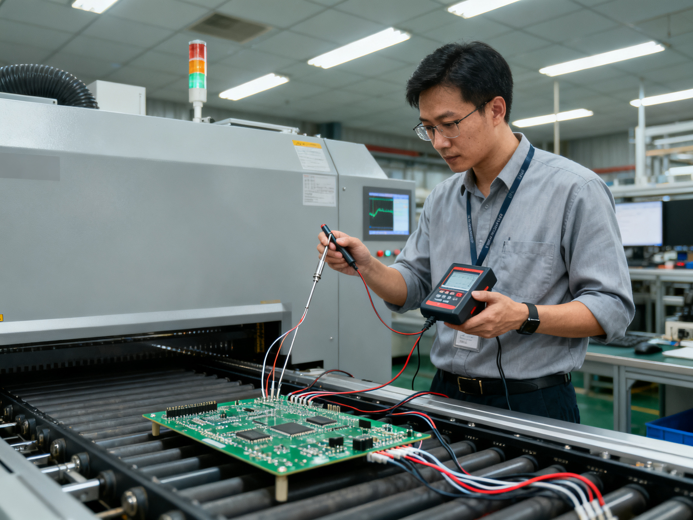
reflow oven temperature profile using thermocouples on test board.
Low-Temperature vs High-Temperature Solder Paste: When Each Makes Sense
Here’s the thing about choosing solder paste: there is no universal winner. The “best” paste always depends on your specific board, your components, and what your product needs to survive out in the world.
Low-temperature Sn-Bi paste works beautifully for heat-sensitive assemblies. It drops your reflow peak from 240°C down to around 170°C. That 70-degree difference means less warpage, happier components, and lower energy bills. But Sn-Bi joints tend to be more brittle. They do not handle drop shock or high vibration as well as SAC305.
SAC305 stays the go-to choice when your assembly needs to survive harsh conditions. High-temperature operating environments, power electronics, automotive under-hood applications, and anything that faces thermal cycling or mechanical stress. The mechanical toughness of SAC305 joints simply outweighs the thermal benefits of Sn-Bi in these scenarios.
Matching Paste to Your Application
The decision really comes down to answering a few questions:
- What is the maximum temperature rating of your most sensitive component?
- Will the finished product face high operating temperatures or thermal cycling?
- Does it need to survive drop tests or high vibration?
- Are there compliance requirements driving your alloy choice?
If your product lives in a climate-controlled environment and your biggest challenge is thermal stress during assembly, low-temp paste probably makes sense. If it needs to run reliably for years in variable temperatures or handle mechanical abuse, SAC305 is the safer bet.
| Paste Type | Melting Point | Peak Reflow | Best For | Avoid When |
|————|—————|————-|———-|————|
| Sn42Bi57 | 138 to 140°C | 160 to 170°C | Heat-sensitive parts, thin boards, LEDs, flex circuits | Drop shock, high vibration, harsh thermal cycling |
| SAC305 | 217 to 219°C | 235 to 245°C | Standard lead-free SMT, automotive, aerospace, power electronics | Thermally sensitive assemblies |
| Sn63Pb37 | 183°C | 205 to 220°C | High-reliability applications (non-RoHS) | RoHS-restricted products |
Pro Insight: Before committing to any paste, run a validation checklist. Test for voiding under BGAs and QFNs, check wetting on your specific pad finish, verify tombstoning risk with your component placements, and confirm your profile stays within your oven capabilities. Switching from SAC305 to Sn-Bi changes your entire process window, so treat it as a new qualification, not a drop-in replacement.
The bottom line: stop looking for the “best solder paste” and start asking “which paste fits my specific reliability needs and thermal constraints.” That question leads to better decisions every time.
Validation Tests Before Full Production Rollout
Here is the honest truth: switching solder paste is not a flip-of-a-switch decision. If you jump straight from SAC305 to Sn-Bi paste on a full production run without checking things first, you are asking for trouble.
Pilot production is where you catch problems before they cost you. This matters even more for sensitive applications like smartphones, semiconductor modules, automotive control units, and military electronics. Those markets have zero tolerance for field failures, so validation is non-negotiable.
Phased Validation Process
Phase 1: Lab Testing
Start with your engineering team. Run thermal profiling on a representative board using thermocouples at multiple locations. Check voiding under BGAs and QFNs with X-ray inspection. Do shear testing on representative solder joints to establish a baseline.
Phase 2: Pilot Line Run
Once lab results look good, run a small batch through your actual SMT line. Inspect every board for defects. Pull samples for cross-section analysis to verify joint microstructure.
Phase 3: Reliability Testing
This is where you earn confidence. Run thermal cycling tests (IPC-9701/IPC-9701A compliant), and if your product faces vibration or drop shock, include those tests too. For automotive and aerospace, extended reliability testing over hundreds of cycles is standard.
Phase 4: Production Approval
Only after reliability data passes your acceptance criteria do you approve the paste for production use.
Phase 5: Ongoing SPC Monitoring
Keep tracking defect rates, void percentages, and joint quality. Statistical process control catches drift before it becomes a批量 problem.
| Validation Phase | Key Tests | Pass Criteria | Timeline |
|—————–|———–|—————|———-|
| Lab testing | Thermal profiling, X-ray voiding, shear testing | Meets IPC class 3 | 1 to 2 weeks |
| Pilot run | Visual inspection, cross-sections, initial yield | Defect rate under 0.5% | 1 week |
| Reliability testing | Thermal cycling, drop/vibration tests | Passes application requirements | 4 to 12 weeks |
| Production approval | Final data review | Full qualification report | 1 week |
| SPC monitoring | Continuous defect tracking | Control chart within limits | Ongoing |
Why This Pays Off
Skipping validation to save time usually backfires. Reworking a full production run of defective boards costs way more than the weeks you thought you were saving. Plus, catching issues early means you can adjust your reflow profile, paste storage procedure, or printer settings before they become systemic problems across thousands of units.
The validation process also gives your procurement team confidence. When you can show documented test results matching IPC standards, component suppliers and customers take you more seriously. That matters in competitive markets like consumer electronics and automotive.
Bottom line: pilot production is not optional. It is how you protect your yield, your reputation, and your bottom line when switching to low-temperature solder paste.

Conclusion: Practical Selection Guidance for SMT Manufacturers
Low-temperature solder paste, specifically Sn42Bi57 and Sn42Bi57Ag1 alloys, gives SMT manufacturers a real option for assemblies where thermal stress is the enemy. When your components cannot survive 240°C peaks, or when your thin boards warp under standard profiles, Bi-based pastes drop your reflow down to around 170°C and open up possibilities that would otherwise require expensive workarounds or hand assembly.
But here is the honest takeaway: lower reflow temperature does not mean lower standards. Sn-Bi joints are more brittle than SAC305, and that matters for drop shock and high-vibration applications. Before you switch, validate against your actual reliability requirements.
The practical decision path:
- Start with your most temperature-sensitive component and its rating
- Choose alloy and melting point first
- Verify flux chemistry, packaging format, and powder size
- Confirm your reflow oven can hit the profile window
- Run pilot builds and inspect BGA/QFN joints
- Document your process limits before scaling up
If you are still asking “what solder paste should I use,” the answer depends entirely on your board, your components, and what your product needs to survive in the field.
Takeaway: Low-temperature solder paste works when thermal protection matters more than maximum mechanical toughness. For heat-sensitive assemblies, thin boards, and step soldering, Sn-Bi makes sense. For automotive, aerospace, and harsh environments, stick with validated SAC305 profiles.
Need help dialing in your reflow profile or evaluating equipment for low-temp production? S&M Co. Ltd. (Shenzhen Chuxin Electronic Equipment) supports manufacturers transitioning to Bi-based pastes with profiling tools and process optimization guidance. Reach out to discuss your assembly challenges.