



Published: 12 July 2026
Reading Time: 18 minutes
Reviewer: Not specified
Introduction: Why PCB Soldering Skills Matter in 2026
You know that feeling when you finally build that gadget you’ve been dreaming about, only to watch it sit dead on your desk because one tiny joint decided to play hide and seek with conductivity? Yeah, I’ve been there. Multiple times. There’s something uniquely frustrating about watching a $50 project fail because of a botched connection.
PCB soldering isn’t just some dusty skill your grandpa used for radio repair. In 2026, it’s the backbone of everything from the phone in your pocket to the car that drives you to work. And here’s the thing: the difference between a professional-grade joint and a beginner’s mess often comes down to understanding a few key principles.
Modern electronics manufacturing demands precision. We’re talking about components so small you need a microscope just to see them, and tolerances measured in fractions of a millimeter. When done right, soldering creates reliable electrical connections that last years. When done wrong? Well, let’s just say the smoke test becomes more literal than you’d prefer.
The good news is that soldering is a learnable skill. With proper technique and understanding of fundamentals like temperature control and joint formation, you can achieve professional-quality results consistently. This guide walks through everything you need to go from fumbling with your first connection to building confidence in your own craftsmanship.
Jace Liu brings extensive expertise in SMT (Surface Mount Technology) equipment and precision soldering solutions through his work with Shenzhen Chuxin Electronic Equipment Co., Ltd. With years of hands-on experience supporting manufacturers across consumer electronics, semiconductor, and industrial applications, Jace provides practical guidance on soldering techniques and PCB assembly fundamentals.
About the Author
Jace Liu has spent years working alongside manufacturers building everything from smartphones to automotive electronics. His work with Shenzhen Chuxin Electronic Equipment Co., Ltd. means he’s seen firsthand what separates production-line quality joints from amateur attempts. He understands the pressure manufacturers face when tolerances shrink and deadlines loom. Jace shares what actually works in real shop environments, not just textbook theory.
Step 1: Understanding PCB Soldering Fundamentals
Before you touch that soldering iron, let’s make sure you actually know what’s happening when you solder a joint. Trust me, understanding the why makes the how way easier.
PCB soldering creates permanent electrical and mechanical connections between components and circuit boards. The solder acts like a conductive glue, but it’s also doing something more interesting: it forms a metallurgical bond with both the component lead and the pad. That bond is what makes the connection reliable and long-lasting.
We’ve found that beginners who skip straight to “melt solder, hope for best” end up reworking the same joints over and over. The theory matters.
Types of PCB Soldering Techniques
There are three main approaches you’ll encounter:
Through-hole soldering is the classic method. Components have metal legs that poke through holes in the board, and you solder from the opposite side. It’s sturdy and forgiving, which makes it perfect for learning.
Surface mount soldering is how most electronics get made today. Components sit right on top of the pads without any holes. This lets manufacturers pack more stuff into smaller spaces, but it requires steadier hands and better vision (or magnification).
Drag soldering is a technique where you apply solder to multiple pins at once, then use solder wick to remove the bridges. It’s efficient for ICs with lots of pins.
Lead-Based vs Lead-Free Solder: What’s the Difference?
Here’s where things get practical. The type of solder you choose affects everything from temperature settings to how your joints will look.
| Property | Lead-Based | Lead-Free |
|———-|————|———–|
| Melting Point | 183°C (361°F) | 217-221°C (422-430°F) |
| Working Temperature | 250-300°C | 300-350°C |
| Wettability | Excellent | Fair to Good |
| Joint Appearance | Shiny | Duller finish |
| Ease of Use | More forgiving | Requires more skill |
| Health Risk | Contains lead | Lead-free (safer) |
In 2026, lead-free solder is the industry standard because it eliminates toxic lead from manufacturing. But here’s the honest truth: lead-based solder is easier for beginners to work with. The lower temperature and better wetting make it more forgiving of timing mistakes.
If you’re just starting out and working on personal projects, starting with lead-based solder might save you some frustration. You can always transition to lead-free once you have the basics down.
Most beginners ask what temperature to solder PCB boards with. For lead-based solder on standard FR-4 boards, you’re looking at 300 to 320 degrees Celsius. For lead-free, bump that up to 330 to 360 degrees. These ranges give you enough heat to form good joints without frying your components.
The key thing to remember is that you need consistent temperature control. A soldering iron that fluctuates wildly will give you inconsistent results, and that’s how cold joints happen.
Pro Insight: IPC-A-610J sets the standard for what counts as an acceptable solder joint. The key criteria? Your joint should be shiny, smooth, and show proper wetting to both the component and the pad. Dull or grainy joints usually mean something went wrong in the process.
Now that you understand what’s happening at the molecular level, let’s talk about getting your workspace ready.
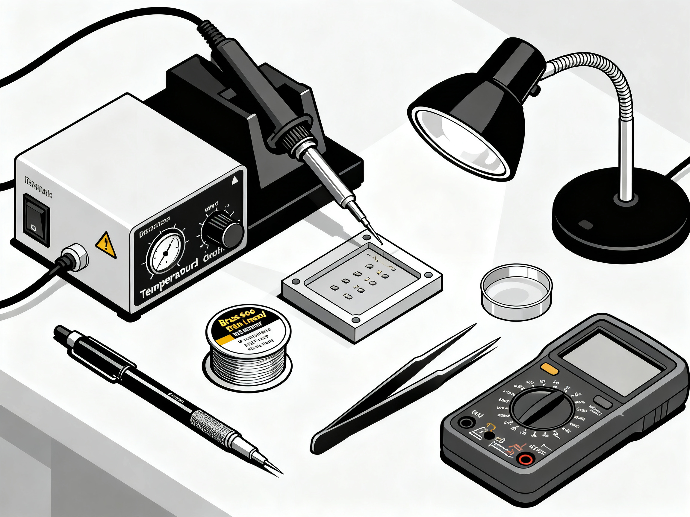
Step 2: Essential Tools and Equipment for Your PCB Soldering Kit
Here’s the honest truth: your soldering results will only be as good as the tools you use. A fancy technique won’t save you from a cheap iron that can’t hold temperature. I learned this the hard way, burning through three terrible knockoff irons before finally upgrading.
The good news? You don’t need to spend a fortune to get started. But you do need the right pieces.
The Foundation: Your Soldering Iron
A temperature-controlled soldering iron is non-negotiable. Skip the cheap fixed-temperature models, because they will frustrate you to no end. Look for these specs:
- Wattage: 20 to 50 watts for PCB work
- Temperature range: 200 to 450 degrees Celsius
- Digital display: Helps you know exactly what temperature you’re running
For beginners in 2026, the USB-C powered stations with digital readouts have gotten really good and affordable. You can grab a solid starter iron for under $30 that will handle 95% of hobbyist projects. When you’re ready to upgrade, brands like Hakko and Metcal are the industry standard.
Pro Insight: An adjustable thermostat is more important than raw wattage. A 45W temperature-controlled iron will outperform a 100W fixed-temperature iron every single time. The temperature stability means consistent joints, and that means fewer callbacks and reworks.
The Essential Accessories
Beyond the iron itself, you’ll need these items:
| Tool | Purpose | Budget Option |
|——|———|—————|
| Brass wool | Tip cleaning (better than wet sponge) | $5-10 |
| Solder wick | Fixing bridges and mistakes | $3-5 |
| Flux pen | Improves solder flow | $8-12 |
| Tweezers | Placing components | $5-15 |
| Magnifying lamp | Seeing tiny details | $20-40 |
| Safety glasses | Eye protection | $5-10 |
| Fume extractor | Staying healthy | $20-50 |
The solder wick and flux? Those are your insurance policy. When (not if) you bridge two pins together, solder wick pulls up the excess like magic. And flux makes everything flow better, especially with lead-free solder.
Building Your First Kit
Start with the basics and add as you go. Most beginner soldering kits come with the essentials, but check that your kit includes:
- A quality iron with adjustable temp
- Multiple tip sizes (conical and chisel are the most useful)
- Lead-free or lead-based solder (your choice)
- The cleaning accessories mentioned above
Here’s a pro move: buy a few extra chisel tips. They’ll wear out faster than you expect, especially if you’re working with lead-free solder at higher temperatures.
One thing beginners often overlook is tip maintenance. Clean your tip before every session, and tin it when you’re done. A well-maintained tip can last months. A neglected one dies in days.
With your station set up, you’re ready to move on to actually prepping your workspace. Let’s make sure you don’t skip this part, because proper setup prevents most beginner disasters.
Step 3: Set Up Your Soldering Station
Here’s where a lot of beginners rush, and I get it. You want to start soldering immediately. But taking five extra minutes to set up properly saves you hours of frustration later.
Your workspace matters more than you’d think. We learned this the hard way when my first few projects kept failing because I was working on a metal desk that reflected heat unpredictably, or under a lamp that created glare on the board.
The Physical Setup
You need a clean, flat, heat-resistant surface. A dedicated silicone mat works great. Make sure you have room for your iron, solder spool, tools, and the board you’re working on. Everything should be within arm’s reach so you’re not fidgeting around mid-joint.
Lighting is crucial. Get a desk lamp that doesn’t create glare on the board. A magnifying lamp with built-in light is even better because you’ll be looking at tiny stuff. Without good light, you won’t see problems until it’s too late.
Ventilation matters too. Lead-free solder releases fumes that aren’t great for your lungs over time. Work near an open window with a fan, or grab a fume extractor. You can find basic models for under $50 that make a big difference.
Getting the Temperature Right
Temperature settings vary by solder type and component sensitivity. Lead-free requires higher temperatures because of its higher melting point. Here’s a quick reference:
| Application | Lead-Based Temp | Lead-Free Temp |
|————-|—————–|—————-|
| Standard components | 300-320°C | 330-360°C |
| Sensitive/delicat components | 260-280°C | 290-310°C |
| Large connectors/thermal mass | 340-360°C | 370-400°C |
Pro Insight: For standard FR-4 PCB boards, aim for the middle of these ranges. Temperature stability matters more than hitting an exact number. An iron that fluctuates wildly between 320°C and 380°C will give you worse results than one holding steady at 340°C.
Let It Warm Up
This step is non-negotiable. Once you set your temperature, wait at least 5 to 10 minutes for the iron to stabilize. Starting too early means inconsistent heat delivery, and that causes cold joints every time.
Most stations have an indicator light that tells you when they’re ready. But here’s a pro move: keep a separate thermometer handy and verify your tip temperature occasionally. Manufacturers can drift over time, and even 15 degrees off makes a difference.
Once your station is stable and your workspace is dialed in, you’re ready to start making joints. Next up: preparing your components.
Step 4: Prepare Your PCB Before Soldering
You wouldn’t paint a wall without cleaning it first, right? Same idea here. A dirty board means your solder won’t stick properly, and that’s how you end up with weak joints that fail later.
Clean the Board
Grab some isopropyl alcohol and a soft brush. Wipe down the pad areas where you’ll be soldering. You’re removing oils from your fingers, dust, and any oxidation that’s built up. For really dirty boards, a mild flux remover works better.
The goal is a clean, slightly dull surface on the copper pads. Shiny doesn’t matter as much as contaminant-free.
Apply Flux
Flux is your best friend here. It does two important jobs: it cleans the metal surfaces as you heat them, and it helps solder flow smoothly into the joint.
Grab a flux pen and apply a thin layer right to the pads you’ll be working on. You don’t need much, just enough to coat the area. For beginners, no-clean flux is the way to go because it doesn’t require washing afterward.
If you’re working with lead-free solder, flux becomes even more critical. Lead-free doesn’t flow as easily as the leaded stuff, so that extra help matters.
Tin Your Iron Tip
Before you start on the actual board, touch your solder iron tip to fresh solder. This coats the tip evenly and ensures heat transfers properly. A well-tinned tip looks shiny and silver, not dark or pitted.
We always do this before every session. It’s a habit that takes two seconds and prevents a lot of headaches. Once your tip is prepped and the board is clean, you’re ready to make your first real connection.
Step 5: Understand Your PCB Layout and Components
Here’s something beginners often skip: reading the board before touching it. I know, it sounds obvious. But trust me, diving in without understanding your layout is how you end up soldering a capacitor backwards or blocking yourself into a corner where you can’t reach other components.
The silkscreen layer on your PCB has reference designators like R1, C3, and U2 printed right on the board. These match up with your component placement diagram or datasheet. Take 30 seconds to match these up before you start. It saves a ton of rework.
Polarized components need extra attention here. Capacitors have a stripe indicating the negative leg. Diodes have a band. LEDs have a longer anode leg. ICs have a dot or notch marking pin one. Get these wrong and your board won’t work, or worse, you might fry something when you power it on.
Here’s the assembly sequence that works best:
-
Start with through-hole components. They’re bigger and easier to place, plus they hold the board together while you work on the smaller stuff.
-
Move to surface mount components next. These are trickier and benefit from having the board stabilized by your through-hole parts.
-
Finish with any delicate or heat-sensitive components last, if possible.
We always double-check the datasheet for any special handling requirements. Some parts have specific mounting orientations or need to be soldered at lower temperatures to avoid damage. Nobody wants to cook a $15 microcontroller because they didn’t read the fine print.
Once you’ve got your layout figured out, you’re ready to actually place and solder components. Let’s get into the hands-on part.
Step 6: Prepare Your Components
Here’s where a lot of beginners skip ahead, eager to get that iron hot. But taking a few minutes to prep your components properly saves you from headaches later. Trust me on this one.
First things first: verify everything matches your bill of materials. Sounds boring, right? But I’ve seen projects get finished only to discover someone grabbed a 10k resistor instead of a 1k. That’s a frustrating way to end a build.
Check the color bands on your resistors, read the codes on capacitors, and make sure you have the right ICs. Most components have markings, but if you’re unsure, that datasheet you downloaded earlier comes in handy. We always double-check before inserting anything because desoldering is way more work than double-checking.
Bending Leads to Fit Your Board
For through-hole parts, look at the component leads and compare them to your PCB holes. Sometimes the spacing is close but not exact, especially on cheaper kits or salvaged parts. Gently bend the leads to match the hole spacing. Go slow and use needle-nose pliers. The goal is a slight inward bend so the component sits flush against the board.
Don’t crush the leads flat. A little spring tension keeps components in place while you solder.
The Pre-Tinning Trick
This is something the pros do, and it makes everything easier. Before you insert a component, tin one pad on your PCB with a small amount of solder. Then insert the component and solder that first pad. The component stays exactly where you put it while you work on the other connections.
It sounds like extra work, but it’s not. It’s actually faster because you won’t be fighting with components that keep falling out.
Once your components are prepped and verified, you’re ready for the actual soldering. Let’s get to it.
Step 7: The Core Soldering Technique: Heating and Applying Solder
Alright, this is where things get real. You can have the best pcb soldering iron on the market, but if your technique is off, you’ll still get cold joints. Let’s fix that right now.
The secret to good soldering is simultaneous heat transfer. You need to touch both the pad AND the component lead at the same time. Here’s how:
- Place the tip of your iron on the pad
- Rest the component lead against the pad
- Apply pressure for about 2 seconds to bring both up to temperature
- Add solder to the joint area (the point where pad and lead meet), NOT to the iron tip itself
- Watch for the solder to melt and flow smoothly
- Remove the iron
That’s it. The whole motion takes maybe 3 seconds once you get the hang of it.
From Our Experience: The biggest mistake beginners make is touching the solder to the iron instead of the joint. If your solder melts on the tip and drips off, you’re heating the iron, not the joint. Touch the solder to the area where pad and lead meet. Let the heat from the workpiece melt the solder.
Another common slip-up? Letting the iron sit too long. More than 4 or 5 seconds and you risk cooking your component or lifting the pad right off the board. We’ve ruined more than a few LEDs this way, and it’s not fun.
The joint is done when the solder has flowed around both the pad and the lead, forming a nice concave fillet. It should look shiny and smooth, not dull or grainy.
If your solder isn’t flowing, check your temperature first. Your pcb soldering temperature range might be off, or your tip might need cleaning. A dirty tip doesn’t transfer heat well.
One more thing: keep the iron tip perpendicular to the board. This gives you maximum contact area and even heating. Angling it too much means uneven heat distribution, and you’ll get partial joints.
Once your iron is hot and your technique clicks, you’ll be able to make solid joints consistently. It just takes a little practice.
Step 8: Soldering Different Component Types
Not all components play nice the same way. A chunky capacitor behaves differently than a tiny chip resistor, and treating them the same is how you end up with frustration and rework. Let’s break down what works for each type.
Through-Hole Components
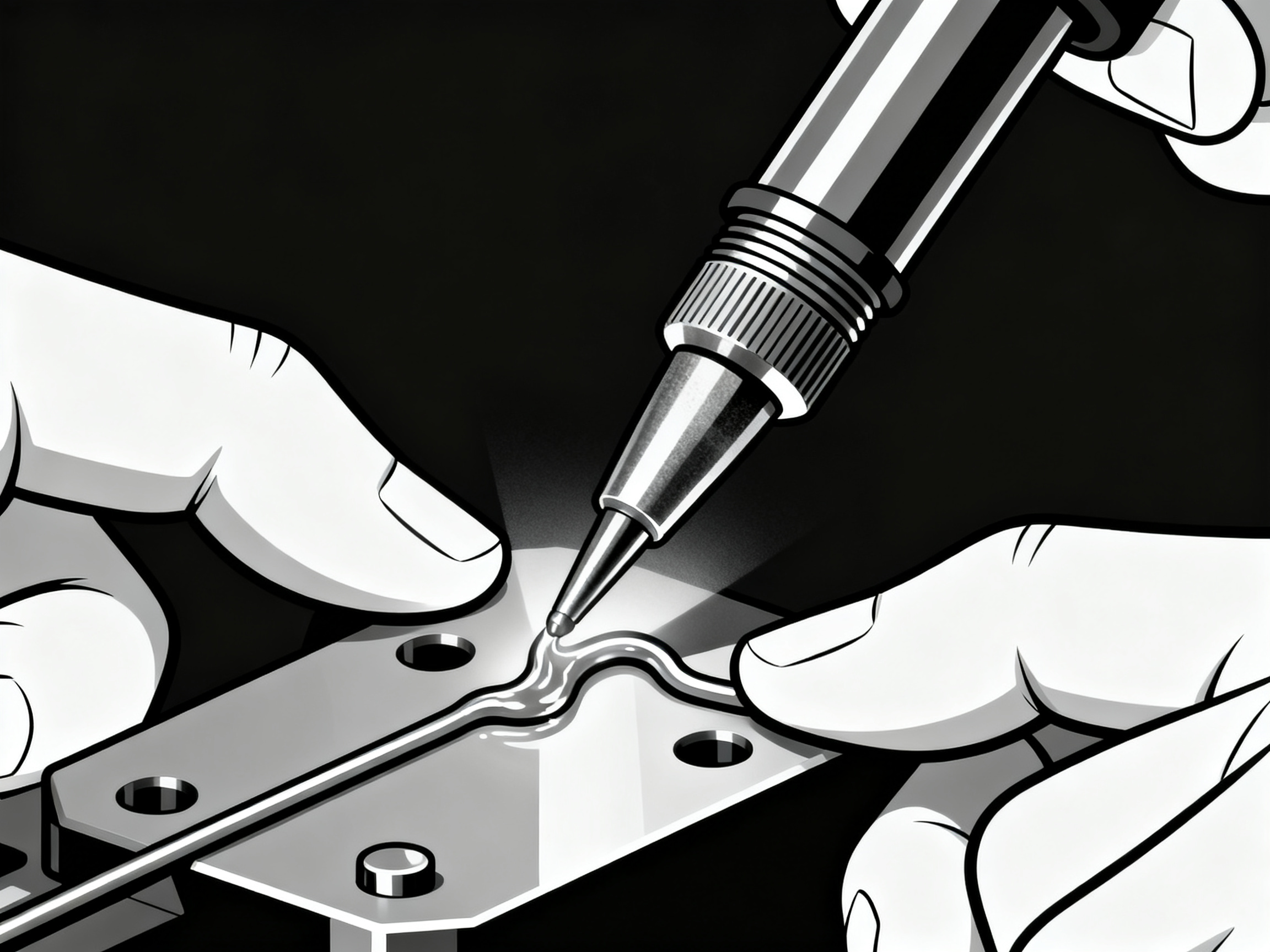
These are the big guys with legs poking through the board. Remember Step 7? Same technique applies, but scale it up.
Heat both the pad and the lead at the same time, wait a couple seconds, then feed solder to the joint, not the iron. Through-hole parts have more thermal mass, so you might need an extra second or two compared to smaller joints.
For components with multiple leads, solder opposite corners first. That holds everything in place while you finish the rest. Trust me, it’s way better than fighting with a part that keeps tilting.
Surface Mount Components
SMD parts sit right on the pads without holes. They’re smaller, but the core principle stays the same.
For resistors and capacitors with two terminals, touch both pads and leads simultaneously with your iron, add solder, and done. Simple enough.
For ICs with lots of pins, you have two paths:
Drag soldering works well for standard pitch packages. Apply flux liberally, tack down two opposite corners, then drag a solder bridge across all the pins. Use solder wick to remove the bridges, and you’re left with clean joints.
Soldadura por refluxo is the professional way to handle fine-pitch ICs. Apply solder paste with a stencil or syringe, place the component, and heat until the paste melts and flows. Hot air stations work great for this in 2026, and the results are much more consistent than hand dragging.
| Component Type | Recommended Technique | Difficulty |
|—————|———————-|————|
| Through-hole | Standard iron technique | Easy |
| 2-pin SMD | Direct soldering | Easy |
| SOIC/QFP | Drag soldering + wick | Moderate |
| Fine-pitch (≤0.5mm) | Reflow/hot air | Advanced |
| BGA | Reflow oven required | Expert |
Fine-Pitch ICs and Magnification
Here’s where beginners often struggle. Those tiny pins on a TQFP or QFN package look intimidating, and honestly, they are.
You need magnification. A 10x to 20x microscope or magnifying lamp isn’t optional here, it’s essential. Without it, you’re guessing, and bridges happen.
Fine-pitch work also demands a steady hand and good lighting. Work slowly, apply flux before you start, and don’t rush the alignment. Getting it right the first time beats desoldering a 32-pin chip every single time.
Once you’ve got the different component types down, the next step is checking your work.
Step 9: How to Remove Soldering from a PCB Board
Look, mistakes happen. Even experienced solderers mess up, and sometimes you need to remove a joint to fix a bridge or replace a faulty component. Knowing how to desolder properly keeps your board intact.
Using Solder Wick (Desoldering Braid)
Solder wick is basically copper braid that soaks up molten solder like a sponge. Here’s how it works:
Place the braid right on top of the joint you want to clear. Press your hot soldering iron down on the braid and wait. The heat travels through the copper and melts the solder underneath. Once liquid, the solder wicks up into the braid. Lift both the iron and braid away together, then check the joint.
The trick is feeding fresh sections of braid as you go, since each part only works once. Flux-covered wick flows better and cleans up faster.
When to Grab a Solder Sucker
A solder sucker (or desoldering pump) handles through-hole components with multiple pins much faster. First, melt the solder on one joint. Then position the pump over that spot, trigger it to create suction, and watch it pull the molten solder right out. This is much quicker than wick for larger connections with lots of thermal mass.
Heat one pin at a time for best results. Let the joint cool slightly between attempts to avoid overheating the pad.
Reheating and Component Removal
Sometimes you need to remove an entire component. For multi-pin parts, heat all the joints at once using a copper bar bridged across the pins, or use a hot air station for surface mount pieces. Whatever method you choose, patience is key. Rushing leads to lifted pads, and that’s a whole different problem.
Expert Tip: After removing solder with either method, check the joint under magnification. You want clean copper pads and free-flowing holes. If solder stays in the barrel, reheat and try again. Never force a component out if solder hasn’t fully melted. That pulls pads right off the board, and repairs get expensive.
Temperature matters here too. Your pcb soldering temperature range should be at the higher end when desoldering, since you’re fighting residual solder that has already oxidized. Bump your iron up about 10 to 15 degrees above your normal working temperature.
Take your time, use plenty of flux, and your board will thank you.
Step 10: Inspection and Quality Control
So you’ve made your joints. Now what? Time to check your work before you power anything on, because catching problems now beats watching smoke escape later.
Visual Inspection First
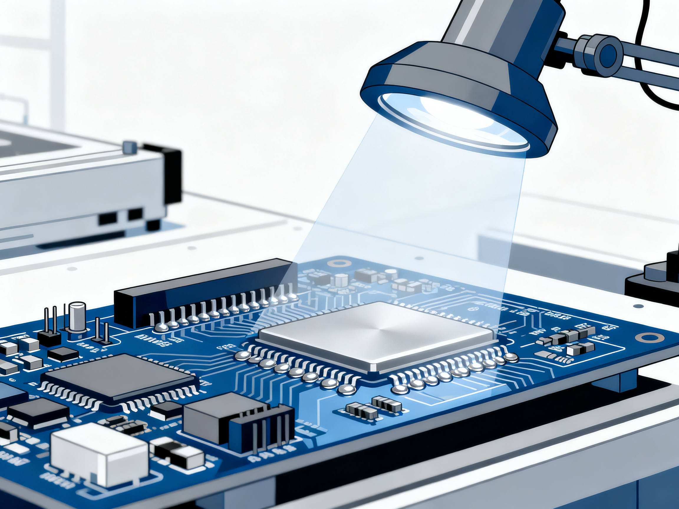
Grab your magnifying lamp and look closely at every joint you made. What you’re hunting for: cold joints that look dull and grainy instead of shiny, bridges where solder connected two adjacent pins that shouldn’t touch, and spots where the solder didn’t quite cover what it should have.
A proper joint has a smooth, concave fillet that rises from the pad edge up to the component lead. The solder should wet both surfaces completely, creating that characteristic shiny appearance. Dull, lumpy, or cracked joints tell you something went wrong during heating. You’ll want to rework those before anything gets powered up.
Expert Tip: IPC-A-610J sets the inspection standards used across the industry. The key thing to remember is that your joints should be shiny and smooth, with visible wetting to both pad and component. If it looks questionable, it probably is. For production work, inspect under 10x to 20x magnification to catch defects invisible to the naked eye.
Test with a Multimeter
Before you power up, grab your multimeter and set it to continuity mode. Touch the probes to either side of each joint. A proper connection gives you a beep and shows near-zero resistance. If you get silence or a high resistance reading, that joint didn’t form right and needs re-soldering.
Check the joints on polarized components like capacitors and diodes twice. Get these backwards and your board becomes a very expensive paperweight. We’ve seen it happen, and it’s not fun debugging a dead device when you forgot which way a cap should go.
The Smoke Test Reality Check
If your visual inspection and continuity tests pass, you’re probably good to power on. Start low, like with a bench power supply limited to 500mA, and watch what happens. Any popping, smoking, or magic smoke escaping means you missed something. Cut power immediately and re-inspect.
Taking a few minutes to verify your work saves hours of troubleshooting later. Trust me on this one.
Step 11: Common Soldering Mistakes and How to Avoid Them
Every solderer, no matter how experienced, has made these mistakes. The good news? They’re all fixable once you know what causes them.
Cold Joints
Cold joints happen when you don’t apply enough heat. The solder melts, but it doesn’t actually bond to the pad or component lead. You’ll recognize these because they look dull, grainy, or lumpy instead of shiny and smooth.
The fix? Make sure you’re touching both the pad and the lead simultaneously with your iron for 2 to 3 seconds before adding solder. Your iron needs good contact with both surfaces to bring them up to temperature. Also, check that your tip is clean and properly tinned. A dirty tip won’t transfer heat efficiently.
Pontes de solda
Bridges are exactly what they sound like: solder forming an unintended connection between two adjacent pins. This creates a short circuit, and your board won’t work properly.
Prevention is simple. Keep your tip clean and wipe it on brass wool between joints. Use less solder than you think you need. If a bridge does happen, place solder wick on top of the bridge and press your hot iron down. The solder gets drawn into the wick, clearing the connection.
Lifted Pads
This one hurts the most. A lifted pad happens when you apply too much heat or pull on a component before the solder solidifies. The copper pad literally peels away from the board, leaving you with an open connection and a tricky repair job.
Prevention: keep your iron at the right temperature, and let each joint cool naturally. If you need to remove a component, heat all the pins evenly first. Don’t rush it, and don’t tug on anything while it’s still molten underneath.
Disturbed Joints
Moving a component while solder is still cooling creates disturbed joints. These look rough, pock-marked, or grainy instead of smooth and shiny.
The fix is straightforward: once the solder flows, keep both the component and the board perfectly still for 3 to 5 seconds while the joint cools and solidifies. If you catch yourself reaching for the next component too quickly, pause. Your patience will pay off in cleaner, more reliable connections.
Expert Tip: Use your multimeter’s continuity mode to check questionable joints before powering up. Place one probe on the component lead and one on the pad. A proper joint shows near-zero resistance. Any high resistance or no connection means rework that joint. Better to catch issues now than to release the magic smoke.
These mistakes are all learnable. Each one teaches you something about heat control, timing, and proper technique.
Step 12: Practice Exercises and Next Steps for Improvement
Here’s the thing about soldering: nobody nails it on the first try. Well, maybe someone did, but that person definitely didn’t post their disasters on Reddit. The rest of us mortals need practice, and lots of it.
Start Simple and Build Up
We always recommend beginners begin with through-hole projects. These bigger components give you more target area to hit, and the thermal mass actually helps you feel when heat is transferring properly. A basic Arduino kit or simple digital clock project teaches you the fundamentals without making you want to throw your iron out the window.
Once you can consistently make clean joints on through-hole parts, move to surface mount. Start with 1206-sized components (they’re chunky by SMD standards) before graduating to smaller stuff like 0805, then 0603. Trust me, jumping straight to 0402 components will humble you fast.
Grab a practice kit specifically designed for learning. The CSISLD015 LED Christmas Tree and similar beginner projects give you real components to work with, and you end up with something functional at the end. That’s more motivating than soldering scrap boards with no purpose.
Setting Your Progression Path
| Level | Components | Practice Time |
|——-|———–|—————|
| Beginner | Through-hole only | 1-2 weeks |
| Intermediate | 1206/0805 SMD | 2-4 weeks |
| Advanced | 0603 and fine pitch | 1-3 months |
| Expert | BGA and micro-BGA | 6+ months |
Considering Professional Certification
If you’re serious about electronics, look into IPC certification. The IPC-A-610J standard covers solder joint acceptability, and getting certified shows employers you know your stuff. It’s not cheap, but for career-minded folks in manufacturing or repair, it opens doors.
Most beginners reach basic competency in 1 to 2 weeks of focused practice. Going from there to comfortable with SMD work? Add another month or two. Be patient with yourself. The skills compound, and eventually your hands just know what good looks like.
Advanced Projects to Challenge Yourself
Once you’ve mastered the basics, try these intermediate projects:
- Custom Arduino shield: Design and build your own add-on board with headers, capacitors, and LEDs
- USB-C PD trigger board: Solder small components while building something genuinely useful
- RP2040-based projects: Practice on microcontrollers with fine-pitch pins
These projects bridge the gap between training exercises and real-world applications.
Building Your Portfolio
Document your projects with photos of your solder joints. Share them in communities like r/PrintedCircuitBoard or r/electronics. Feedback from experienced makers accelerates your growth.
Remember: Every expert solderer has a box of early disasters. The difference is they kept learning instead of giving up.
Keep your iron hot, your tips clean, and your patience intact. You’ve got this.
Conclusion: Your Path to PCB Soldering Mastery
You’ve made it this far. You now understand the pcb soldering process from start to finish, and you know what separates a rookie joint from a professional one. But here’s the thing: reading about soldering and actually doing it are two completely different experiences.
The key to getting good is simple: practice, practice, and more practice. Start with through-hole projects, move to surface mount when you feel ready, and keep pushing yourself with harder components. Your hands will remember the timing and temperature before your brain catches up.
Quality tools matter more than most beginners realize. A solid temperature-controlled iron takes the guesswork out of heat management. When your equipment does its job, you can focus entirely on technique.
As you grow, explore more advanced methods like reflow soldering for SMD work or hot air rework for BGA packages. Professional manufacturers like Shenzhen Chuxin Electronic Equipment Co., Ltd. use these advanced techniques to achieve precision results at scale. Understanding the science behind solder flow and metallurgical bonding helps you troubleshoot issues and improve faster.
Stick with the fundamentals, invest in decent equipment, and give yourself permission to make mistakes. Every expert solderer has a box of early disasters. The difference is they kept at it.
Now get out there and start building.
Frequently Asked Questions About PCB Soldering
Got questions? You’re not alone. Here are the most common ones I hear from beginners and even some intermediate solderers.
What temperature should I set my soldering iron for PCB work?
The answer depends on your solder type. For lead-free solder on standard FR-4 boards, aim for 350 to 380 degrees Celsius. That’s on the higher end because lead-free doesn’t transfer heat as easily as the old-school stuff. If you’re using lead-based solder, you can work cooler at 315 to 345 degrees Celsius. Start in the middle of those ranges and adjust based on how your joints look. Consistent temperature matters more than hitting an exact number, so if your iron fluctuates wildly, you’re better off with a quality station.
What kind of soldering iron do I need for PCB work?
Skip the cheap fixed-temperature models. You want a temperature-controlled iron in the 30 to 60 watt range with a fine tip. The thermostat control is more important than raw wattage here. A 45W temperature-controlled iron outperforms a 100W fixed-temperature iron every single time. For beginners in 2026, USB-C powered stations with digital displays have gotten really good and affordable. You can find solid starter irons for under $30 that handle most hobby projects. When you’re ready to upgrade, brands like Hakko and Metcal are the industry standard.
What solder works best for PCB boards?
For electronics work, use rosin core solder designed specifically for electronics. Lead-free rosin core is the standard in 2026 because it eliminates toxic lead from your workspace. Choose your gauge based on component size: larger gauge for through-hole work, finer gauge (0.5 to 0.8mm) for surface mount components. The SAC305 alloy, containing 96.5% tin, 3% silver, and 0.5% copper, remains the most common lead-free option. It balances performance, cost, and reliability pretty well.
How long does it take to learn PCB soldering?
Basic competency usually takes 1 to 2 weeks of focused practice. Getting comfortable with surface mount work adds another month or two. Nobody masters this overnight, and that’s completely normal. Start with through-hole kits, move to 1206-sized SMD components, then graduate to smaller parts as your confidence grows.
What safety gear do I need?
Safety glasses with side shields are non-negotiable. A fume extractor or at least working near an open window with a fan keeps your lungs happy. Isopropyl alcohol for cleanup and a heat-resistant mat complete the basics. You don’t need to go overboard, but these essentials protect you during every session.