



Published: 09 August 2026
Reading Time: 10 minutes
Why the Best Solder Joint Matters for High-Reliability Electronics
You know that sinking feeling when a batch of assemblies comes back from the field? Four months into production, suddenly you are looking at warranty claims, customer complaints, and a scramble to figure out what went wrong. Spoiler alert: more often than not, the root cause traces back to the solder joints.
Here is the uncomfortable truth nobody talks about enough. Solder joint defects account for more than 70% of all PCB assembly failures in high-reliability products. That is not a typo. Three out of four failures trace directly to how those tiny connections were made during manufacturing. In automotive, aerospace, and military applications, a single joint failure can mean expensive recalls, compliance failures, or worse.
Now, here is where it gets interesting for anyone running a production floor. The best solder joint is not just about looks. Sure, nobody wants a joint that looks like a cold mess. But real reliability comes down to what you cannot see. We are talking about repeatable wetting that creates strong metallurgical bonds. Correct geometry that survives thermal cycling. Low voiding that prevents hot spots. Mechanical strength that holds up under vibration. And long-term electrical stability that does not drift over years of use.
For decision-makers evaluating SMT process upgrades, lead-free compliance, precision reflow ovens, or complete production lines, this stuff matters more than ever. The gap between a good solder joint and the best solder joint for your specific application? It shows up in your defect rates, your rework costs, and whether your customers keep coming back.
This guide breaks down the techniques, comparisons, and product insights you need to make smart choices about solder joint quality in 2026. Whether you are running consumer electronics, semiconductor packaging, or mission-critical automotive builds, we have got you covered.
About the Author
Jace Liu works as an overseas market and technical communication specialist at Shenzhen Chuxin Electronic Equipment Co., Ltd. Based on their LinkedIn profile, they hold a Master’s degree in International Human Resource Management from the University of Exeter and a Bachelor’s degree in Business Administration from the University of Glasgow. Prior experience includes project management at Foxconn and consulting roles before joining Shenzhen Chuxin in 2024. Their focus centers on comprehensive SMT soldering solutions, addressing common challenges in reflow, wave, and selective soldering processes for electronics manufacturing services factories worldwide. (Author credentials related to SMT process background, equipment expertise, or soldering reliability qualifications are pending verification and will be updated once confirmed.))
What Makes the Best Solder Joint Reliable in 2026?
Here is something that surprises a lot of people. A solder joint can look absolutely perfect under magnification and still fail in six months. Conversely, one that does not win any beauty contests might hold up for 15 years in the field.
The difference comes down to what is happening beneath the surface.
A reliable solder joint starts with good wetting. That means the molten solder flows and bonds properly with both the component lead and the PCB pad, creating a strong metallurgical connection. You want to see that smooth, concave fillet shape that tells you the solder grabbed on properly.
Then there is the intermetallic compound layer. This forms where the solder meets the metal surfaces, and it needs to be just right. Too thin and the bond is weak. Too thick and it becomes brittle. Getting this right during your reflow soldering profile setup makes a huge difference for long-term durability.
Voiding matters too. Small voids are normal, but excessive voiding creates hot spots and weakens mechanical strength. For BGA solder joint reliability, industry guidance typically targets under 25-30% voiding. For QFN thermal pads, you might see thresholds around 50% depending on your application.
What about the difference between what looks good and what actually lasts? Check out this comparison:
| Visual Quality Indicators | Reliability Indicators |
|—————————|————————|
| Smooth, shiny surface | Proper wetting and IMC formation |
| Complete fillet coverage | Low voiding (industry thresholds) |
| No visible bridging | Mechanical strength under vibration |
| Correct fillet geometry | Survival through thermal cycling (-40°C to +125°C) |
| Clean appearance | Stable electrical resistance over time |
The best solder joint for your wires needs to handle movement and flexing without cracking. Through-hole joints need good solder flow through the barrel. BGAs and QFNs demand precise temperature control during reflow. Fine-pitch ICs need to avoid bridging while still achieving proper wetting.
So the real question is not just “does it look right?” It is “will this joint survive the conditions my product will actually face?”
Best Solder Joint for Wires vs SMT Components: Key Differences
Look, if you have been doing electronics work for a while, you probably learned to solder wires first. And that experience is valuable. But here is the thing that trips up a lot of people when they move into production work: the best solder joint for wires is not the same beast as the best solder joint you need for BGA or QFN components.
Wire joints care about different stuff. You need good mechanical support, proper tinning of the strands, strain relief so the joint does not crack when things move around. Insulation clearance matters too, and you have to avoid solder wicking up under the insulation where it can cause all sorts of problems. Hand-soldering techniques work fine for most wire work, and the IPC/WHMA-A-620 standard gives you clear guidance on fill requirements depending on your class level.
SMT joints play by completely different rules. Pad design, stencil aperture geometry, solder paste deposition volume, component placement accuracy, and your reflow profile all converge to determine whether you get a good joint or a defect. Visual inspection alone is not enough. You need X-ray inspection for hidden joints, thermal profiling to validate your process, and SPC data to keep things in control.
This difference matters more than most people realize. I have seen engineers with years of hand-soldering experience apply those same instincts to BGA rework and wonder why the results are so inconsistent. The thermal mass, the precision required, the consequences of getting it wrong: it is a different ballgame entirely.
| Solder Joint Type | Primary Quality Factors | Inspection Method | Common Failure Mode |
|——————-|————————|——————-|———————|
| Wire/Through-hole | Wetting, fillet shape, strand integrity | Visual magnification | Cold joint, cracked wire |
| Gull-wing (SOP/QFP) | Coplanarity, fillet coverage, heel fillet | Visual + AOI | Insufficient wetting |
| BGA (ball grid array) | Voiding, collapse, self-alignment | X-ray inspection | Head-in-pillow, opens |
| QFN (quad flat no-lead) | Thermal pad voiding, side wall wetting | X-ray + thermal imaging | Lifted component, dry joint |
| Fine-pitch IC | Bridge prevention, solder volume | AOI + 2D X-ray | Bridging, insufficient paste |
The takeaway? Know what you are working with. Wire experience is great foundation knowledge, but do not assume it translates directly to high-density SMT production without adjusting your expectations and your process controls.
How to Achieve the Best Solder Joint: Process Parameters and Best Practices
Now that we have covered the different methods and what makes a joint reliable, let us get into the practical stuff. How do you actually achieve the best solder joint in your production environment?
It starts with understanding that every parameter in your process is interconnected. Change one thing and you are affecting three others.
Reflow Profile Optimization
Your reflow profile is not a one-size-fits-all setting. It needs to match your specific board stackup, component thermal mass, and solder paste manufacturer recommendations. The four key zones are:
Preheat Zone: Ramp rate matters here. Too fast and you get thermal shock. Too slow and you activate flux too early. Industry best practice keeps ramp rates between 1-3°C per second for most assemblies.
Soak Zone: This is where you want to even out temperatures across the board and prepare the flux for the reflow stage. A typical soak might run 60-120 seconds between 150-180°C, but this varies with OSP, ENIG, and HASL finishes.
Reflow Zone: Peak temperature and time above liquidus are critical. For SAC305 solder, you are typically targeting 235-245°C peak with 60-90 seconds above 217°C. Exceeding 260°C for more than a few seconds starts degrading intermetallic compounds.
Cooling Zone: Controlled cooling prevents thermal shock and helps with grain structure. Cooling rates of 4-6°C per second are typical, but BGAs may benefit from slower cooling to reduce warpage.
Solder Paste Selection
Choosing the right solder paste affects everything downstream. Lead-free SAC305 remains the workhorse for most applications, but SnBi and SnBiAg options offer lower temperature processing for temperature-sensitive components.
Particle size matters for fine-pitch applications. Type 3 or Type 4 paste works for most 0402 and larger components. For 0201 and fine-pitch QFNs, you want Type 5 or smaller particles to prevent stencil printing issues.
Flux activity level needs to match your surface finish. High-activity pastes work well with OSP but may be overkill for ENIG. Medium-activity formulas often provide the best balance for mixed-technology boards.
Stencil Design for Optimal Paste Deposition
Paste volume directly affects joint quality. Too little and you get insufficient wetting and opens. Too much and you get bridging and tombstoning.
Aperture design should follow the 0.66 ratio guideline for most applications. That means the aperture should be about 66% of the pad size. For QFNs with thermal pads, window pane and cross-hatch designs help control voiding while maintaining printability.
Stencil thickness selection balances between adequate volume for larger pads and precise control for fine-pitch areas. Laser-cut stencils with nano-coatings provide the best release characteristics.
Inspection and Verification
You cannot improve what you do not measure. AOI catches obvious defects but misses hidden issues in BGA and QFN joints. X-ray inspection reveals voiding, alignment, and solder fill that visual inspection cannot see.
Thermal profiling should be run quarterly at minimum, and whenever you change board designs, components, or paste types. A single thermocouple failure can invalidate your entire profile.
Defect data tracking over time reveals process drift before it becomes a quality crisis. Pareto analysis helps you focus improvement efforts on the 20% of defects causing 80% of your problems.
The best solder joint results come from treating your process as a system rather than a collection of independent steps. Each decision compounds on the others, and the cumulative effect shows up in your DPMO numbers and field reliability.
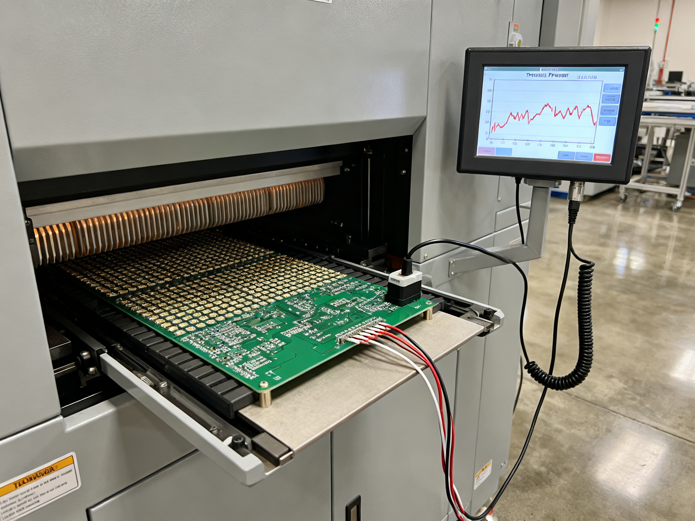
How to Optimize Lead-Free Reflow Profiles for Strong SMT Solder Joints
Let me get real with you. Most production floors are running their reflow ovens on factory default recipes, and that is basically playing Russian roulette with your defect rate. The oven manufacturer has no idea what board stackup you are running, what components you have placed, or what solder paste you selected. Their defaults are a starting point, nothing more.
Your reflow profile is a precision instrument. Mess with one setting and you trigger a cascade of problems downstream.
Breaking Down the Profile Stages
Preheat: This is where you set the stage. Your ramp rate here, typically 1-3 degrees Celsius per second, determines whether components survive the thermal journey. Too fast and you get thermal shock that cracks BGA joints. Too slow and your flux activates too early, leaving it exhausted before it can do its job at peak temperature.
Soak Zone: Think of this as the equalizer. You want all the thermal mass on your board to catch up before hitting liquidus. A typical soak runs 60-120 seconds between 150-180 degrees Celsius, but OSP finishes need different handling than ENIG or HASL.
Time Above Liquidus: For SAC305 solder, you need about 45-90 seconds above 217 degrees Celsius. This is when the magic happens, but also where damage occurs if you push too hard.
Peak Temperature: Here is where people mess up. Too low and you get cold solder joints, opens, and insufficient wetting. Too high and you damage components while creating brittle intermetallic layers that crack under thermal cycling. Target 235-245 degrees Celsius for most assemblies.
Refroidissement : Controlled cooling at 4-6 degrees per second prevents thermal shock and gives you a clean grain structure. Skip this and your joints will be stressed from day one.
What Goes Wrong With Bad Profiles
Wrong profiles create predictable defects. Tombstoning happens when one pad heats faster than the other. Voiding spikes when ramp rates are off. Solder balls appear from rapid moisture release. And those brittle intermetallics? They form when peak temperature or time above liquidus gets too aggressive.
Expert Tip: Always validate your profile with actual thermal profiling on your specific board. Run thermocouples on the hottest and coldest points of a representative load. Do not trust default recipes or assumptions. Check quarterly minimum, and whenever you change board designs or paste types.
Equipment Capabilities Matter
Your oven needs to deliver on the fundamentals. Multi-zone heating gives you control over each profile stage. Conveyor stability ensures consistent contact time. Thermal uniformity, ideally delta-T under 3 degrees Celsius across your board, prevents hot spots that create field failures. Nitrogen atmosphere options reduce oxidation and improve wetting, especially helpful for OSP and NiPdAu finishes where targets under 100 ppm O2 make a real difference.
The bottom line? That default recipe on your reflow oven is costing you money in rework and field failures. Profile it, validate it, and control it.
Common Solder Joint Defects in BGA, QFN, and High-Density Assemblies
Here is where things get tricky. In high-density assemblies, the defects that matter most are the ones you cannot see with your eyes. BGA and QFN packages hide their failures beneath the component body, which means visual inspection only catches about 30% of the problems. The rest? They show up months later in the field.
The usual suspects show up across all assembly types. Voiding happens when trapped gases create pockets inside the joint. Bridging occurs when solder flows where it should not, connecting adjacent pads. Insufficient solder leaves joints weak and prone to failure. Non-wetting and dewetting mean the solder never properly bonded to the surface. Head-in-pillow is that infuriating defect where the BGA ball and paste look joined but actually separated. Tombstoning lifts one side of a component off the pad. Solder balls are little spheres that escape onto the board surface. And cold joints result from temperatures that never quite reached proper reflow.
Each of these has a tell-tale sign and a root cause.
| Symptom | Likely Cause | Inspection Method | Corrective Action |
|———|————–|——————-|——————-|
| Excessive voiding | Ramp rate too fast, moisture contamination, paste chemistry | X-ray inspection | Adjust preheat, dry components, verify paste shelf life |
| Bridging between pads | Stencil aperture too large, paste volume excess, component placement shift | AOI, 2D X-ray | Reduce aperture size, verify placement accuracy, check squeegee pressure |
| Head-in-pillow | Component oxidation, insufficient paste melt, pad flatness issues | Cross-section, thermal profiling | Improve storage handling, optimize reflow profile, verify incoming component quality |
| Tombstoning | Uneven pad heating, unequal paste volume, large thermal mass difference | AOI, visual inspection | Balance pad sizes, adjust soak zone, verify thermocouple placement |
| Cold solder joint | Peak temperature too low, time above liquidus insufficient | Visual, cross-section | Raise peak temp, extend dwell time, verify thermal profile accuracy |
| Non-wetting/dewetting | Surface contamination, oxidation, incorrect surface finish | Visual, solderability testing | Clean boards, verify ENIG/HASL quality, check storage conditions |

Pro Insight: For production inspection workflows, combine AOI for obvious defects like bridging and tombstones, with X-ray for hidden joints in BGAs and QFN thermal pads. Run cross-sections quarterly on representative samples to validate your inspection assumptions. Track defect Pareto data over time to catch process drift before it becomes a quality crisis.
Why does all this matter for your bottom line? A single field failure in automotive or aerospace can cost 10 to 100 times more than the entire inspection setup you skipped to save money. In 2026, with miniaturization pushing tolerances tighter than ever, the assemblers winning on quality are the ones treating hidden defects as the enemy they actually are.
Equipment and Process Controls That Improve Solder Joint Consistency
Here is a truth that took me way too long to learn. You can have perfect solder paste, spot-on reflow profiles, and highly trained operators, and still get garbage joints if your equipment cannot hold tolerances. The equipment between your paste printer and your inspection station matters just as much as the recipe itself.
Think about your SMT line as a chain. Every link needs to be strong.
Paste Printing sets the foundation. Stencil alignment accuracy within 0.05mm, consistent squeegee pressure, and proper paste release directly determine whether you start with correct volume or a downstream nightmare.
Component Placement accuracy matters more than people realize. Placement offset causes offset fillets, insufficient wetting on one side, and tombstoning. Modern pick-and-place systems with vision correction handle 0201s and fine-pitch QFNs, but older machines struggle and you pay for it in defects.
Reflow Oven Control ties everything together. Multi-zone temperature control lets you dial in each profile stage independently. Conveyor speed stability ensures board-to-board repeatability. Thermal uniformity across your board means no hot spots creating weak joints while cooler areas under-reflow.
Wave Soldering Parameters for through-hole and THT assemblies need their own attention. Flux application rate, solder pot temperature, contact time, and wave height all affect fill and joint quality. Selective soldering systems have become popular because they isolate these variables and reduce DPMO dramatically compared to full-wave approaches.
AOI and Feedback Loops close the control system. Automated optical inspection catches obvious defects while statistical process control data tracks trends before they become crises.
From Our Experience: Stable conveyor speed, multi-zone temperature control, nitrogen atmosphere options, and proper flux management have repeatedly proven themselves as the biggest levers for reducing recurring solder defects in high-volume production lines. In our work with EMS factories, the combination of these four factors typically cuts defect rates by 30-40% when properly integrated.
What should you look for in equipment for 2026? Temperature uniformity of delta-T under 3 degrees Celsius across your board, oxygen levels under 100 ppm if you are running nitrogen, data logging on every critical parameter, and reasonable serviceability so downtime does not kill your throughput.
Shenzhen Chuxin Electronic Equipment focuses on these fundamentals across their reflow oven and wave soldering lines. Their systems emphasize the control loops that matter for production consistency, which is why they have become a go-to for manufacturers moving away from legacy equipment that cannot hold modern tolerances.
The bottom line? Invest in equipment that gives you control and visibility. Guesswork is expensive.
How to Evaluate Solder Joint Kits, Fittings, and Production Equipment
Here is a question that comes up constantly in procurement conversations. Someone searches “price solder joint kit” and gets results ranging from a $15 hobbyist iron kit to a $150,000 industrial reflow oven. These are completely different products serving completely different purposes, and mixing them up leads to bad purchasing decisions.
Let me break down what you actually need to look for depending on your situation.
For Consumer Repair and Field Service
If you need solder joint kits for board repair, component replacement, or hobbyist work, you are looking at hand tools, flux, solder wire, and basic inspection magnifiers. Price ranges from $20 to $200 depending on quality. You care about ergonomics, tip life, and whether the iron heats up fast enough for sensitive components.
For Plumbing and Electrical Fittings
These are completely different products. Copper pipe fittings, electrical solder terminals, and mechanical joints have their own standards and applications. If this is what you meant by your search, you need to look at plumbing codes, electrical ratings, and material compatibility rather than anything covered in this guide.
For Industrial SMT Production
This is where things get serious and expensive. Industrial solder joint fittings and SMT equipment prices reflect the capability you need:
| Equipment Category | Price Range | Best For | Key Considerations |
|——————-|————-|———-|——————-|
| Low-cost kits | $50-500 | Hobbyists, light repair | Limited throughput, basic temperature control |
| Benchtop systems | $3,000-15,000 | Prototyping, low-volume | Single-board processing, manual handling |
| Industrial SMT lines | $25,000-150,000+ | High-volume production | Thermal uniformity, automation, DPMO targets |
What to Request Before Buying
Do not buy production equipment based on a brochure. Ask suppliers for:
- Full thermal profiling specifications and delta-T data
- Sample testing or demonstration on your actual boards
- Integration support and installation documentation
- Spare parts pricing and availability timelines
- Warranty terms and service level agreements
- Reference customers in your industry
Buyer Checklist: Confirm the equipment meets your reliability class requirements (Class 1, 2, or 3 per IPC standards), matches your throughput needs, provides adequate thermal control for your board stackup, and offers service support within your operational timezone. Factor in total cost of ownership over five years, not just purchase price.
The cheapest option is rarely the cheapest over time. Shenzhen Chuxin Electronic Equipment provides detailed technical specifications upfront, including thermal uniformity data and DPMO benchmarks, which helps procurement teams make comparisons based on real capability rather than just sticker price.
What is your defect rate target? What is your throughput requirement? Answer those two questions first, then find equipment that meets both without compromising on thermal control or service support.
Quality Validation: How to Prove You Have the Best Solder Joints
Here is the uncomfortable reality. Without proper validation, you have no idea if your “good” solder joints are actually reliable or just waiting to fail in the field.
Validation Methods That Actually Matter
You need to match your inspection method to the defect you are hunting. Visual inspection catches surface issues but misses everything hidden under BGA and QFN packages. AOI handles obvious problems like bridging and tombstones. X-ray reveals voiding, alignment, and solder fill in hidden joints. ICT catches electrical opens and shorts. Functional testing validates the circuit actually works.
For mechanical validation, pull and shear testing quantifies joint strength. Cross-section analysis shows what is happening beneath the surface. Thermal cycling and vibration testing prove long-term reliability under real-world stress. Reliability sampling puts representative joints through accelerated aging to predict field performance.
Define Your Acceptance Criteria First
This step gets skipped way too often. Production teams should establish acceptance criteria before mass production starts, not after. IPC-A-610J covers visual acceptability while J-STD-001J addresses process and material requirements. For BGA voiding, IPC-7093A guidance targets under 25-30% for most applications. Automotive customers often demand under 10% for thermal pads.
| Inspection Method | Defects Found | Best For | Limitations |
|——————-|—————|———-|————-|
| Visual/AOI | Bridging, tombstones, surface defects | Surface-mount quality | Cannot see hidden joints |
| X-ray/AXI | Voiding, alignment, head-in-pillow | BGA, QFN inspection | Equipment cost, training |
| Cross-section | IMC layer, internal cracks, wetting | Process validation | Destructive, sampling only |
| Thermal cycling | Fatigue cracking, delamination | Reliability qualification | Time-intensive testing |
Traceability for High-Reliability Sectors
Military, aerospace, automotive, and semiconductor customers require full traceability. That means documentation linking each defect back to specific production lots, component batches, operator shifts, and equipment settings. In 2026, automated data collection makes this easier than ever, but only if you set it up from day one.
Process capability monitoring, typically expressed as Cpk values, tells you whether your process is in control and meeting specifications. Target Cpk above 1.33 for critical joints. Anything below 1.0 signals problems that need immediate attention.
The goal is proving your joints will last, not just hoping they look good.

Expert Takeaway: Build the Best Solder Joint Through Process Control, Not Guesswork
After all the techniques, comparisons, and equipment insights we have covered, here is what it really comes down to.
The best solder joint is not a single thing. It is a combination of the right assembly type, materials that match your application, a soldering method that fits your production volume, process stability that holds up shift after shift, and verification standards that prove what you built will last.
High-reliability manufacturing does not happen by accident. It requires equipment that delivers consistent thermal performance, process recipes tuned to your specific board stackup, inspection systems that catch the defects you cannot see, and trained engineering judgment that knows when to deviate from defaults. These four elements have to work together.
Your Next Steps
For procurement and production leaders ready to move forward:
- Audit your defect data over the past six months. Build a Pareto chart. Focus on the 20% of defects causing 80% of your problems.
- Validate your reflow and wave soldering profiles with actual thermal profiling on your boards. Thermocouples on the hottest and coldest points. Do not trust defaults.
- Review your inspection capability. AOI alone is not enough if you are running BGAs or QFNs. Budget for X-ray.
- Compare your equipment specs against your reliability goals. Delta-T under 3 degrees, oxygen levels under 100 ppm if running nitrogen, data logging on every critical parameter.
- Set Cpk targets above 1.33 for critical joints and track them monthly.
Organizations that treat process control as a discipline, not a suggestion, consistently outperform their competitors on DPMO and customer satisfaction. The best solder joint is built by design, not discovered by luck.
From Our Experience: Across thousands of production lines we have supported, the factories that cut defect rates by 30-40% share one common trait. They stopped treating the oven as a black box and started managing it as a precision instrument. Profile it, validate it, control it, and your customers will notice the difference in field reliability.