
Author: Jace Liu
Objavljeno: 17 July 2026
Zadnje ažuriranje: 17 July 2026
Vrijeme čitanja: 12 minuta
Recenzent:
—> Objavljeno: 17 July 2026
Vrijeme čitanja: 12 minuta
Recenzent: Simon Scrapes, Founder
Why Wave Soldering Parameters Matter in 2026
Last Tuesday, a production line in Shenzhen ground to a halt. The culprit? Someone bumped the wave height on a wave soldering machine by just 2 millimeters. The result was 400 boards with bridges and shorts, worth about $12,000 in scrap.
Sound dramatic? It happens more often than you’d think.
Small changes in wave soldering parameters quietly make or break your production. A preheat that’s off by 15 degrees can leave flux exhausted before the board even touches the solder. Conveyor speed that creeps 10% faster cuts dwell time short, leaving holes half-filled. Even solder temperature swings of 5 degrees affect how well everything wets together.
These aren’t exotic edge cases. They’re the daily reality in high-volume PCB assembly across consumer electronics, automotive, semiconductor, aerospace, and military manufacturing. Getting these parameters right directly impacts your yield, your defect rate, and ultimately your bottom line.
This guide cuts through the noise. You’ll learn how wave soldering parameters work, how they are determined, how they are calculated, and how to optimize them for reliable production. We’ll look at the critical wave soldering machine settings, the best wave soldering parameters for different PCB types, and the common mistakes to avoid.
Whether you’re setting up a new machine, troubleshooting defects, or optimizing for a new board design, you’re in the right place. Let’s get into it.
Author: Jace Liu
Here is a quick preview of how defects connect to specific parameter issues:
| Defect Type | Common Parameter Cause |
|————-|———————-|
| Bridging | Excessive wave height, slow conveyor speed |
| Insufficient hole fill | Low preheat, fast conveyor speed |
| Solder balls | Inadequate preheat, turbulent wave |
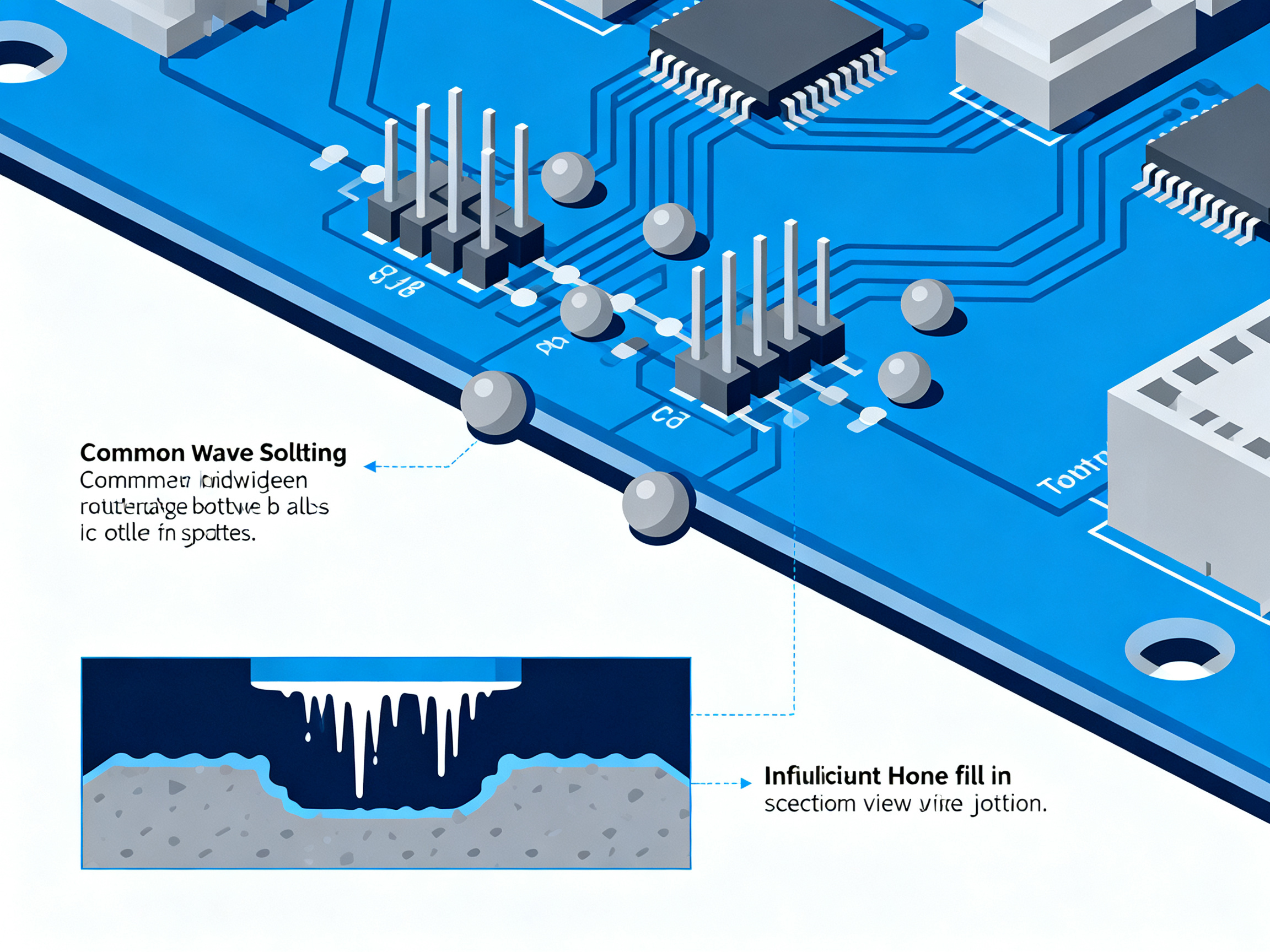
| Icicles | Low solder temperature, steep board angle |
| Dross | Lack of nitrogen, contaminated solder pot |
Keep this table in mind as we work through each parameter in detail. The connections matter.
O autoru
Jace Liu
Author credentials pending verification
Jace Liu has hands-on experience with wave soldering machines, SMT equipment setup, and production-line troubleshooting in electronics manufacturing. Specific professional credentials, certifications, and years of experience will be added once verified and confirmed.
This placeholder ensures all qualifications are properly documented before the article goes live. The content itself covers how wave soldering parameters are determined, calculated, and optimized for different PCB types, along with wave soldering machine settings and common defect solutions.
If you have questions about the technical information presented here, please reach out for clarification.
What Are Wave Soldering Parameters?
Think of wave soldering like cooking. You have a bunch of knobs and dials. Change one, and it affects everything else. That’s exactly how wave soldering parameters work.
Here are the main ones you need to know about in 2026:
Flux Type and Density
Flux is the cleaning agent that readies metal surfaces for solder. You pick the right type based on your board finish, then control the density. Spray fluxers need proper spray volume too. Get it wrong and you either get poor wetting or too much residue.
Preheat Temperature and Ramp Rate
The board gets heated before it touches the wave. Topside needs to hit 100 to 150 degrees Celsius for lead-free work. The ramp rate matters because a too-fast temperature jump cracks boards or damages parts.
Conveyor Speed
This sets how fast the board moves through the wave. Slower speeds mean longer contact with solder, which helps with thick boards but risks overheating sensitive parts.
Solder Pot Temperature
This is the heat of the molten solder itself. For lead-free SAC alloys, you’re looking at 255 to 265 degrees Celsius. Too cool and solder won’t wet properly. Too hot causes other headaches.
Dwell Time (Contact Time)
That’s how long the board actually sits in the wave. For lead-free, you want 3 to 6 seconds. Too short gives you cold joints. Too long risks damaging everything.
Wave Height
This controls how much solder touches the board. Set it around half to two-thirds of your board thickness. Too high and you get bridges. Too low and holes won’t fill properly.
Board Angle
This is the tilt of the conveyor. Most machines run between 5 and 7 degrees. That slight angle helps solder drain off the board properly.
Nitrogen Use
This matters more now with lead-free solder. Adding nitrogen reduces oxidation and improves wetting. You typically want oxygen levels below 50 parts per million at the wave.
How These Settings Interact
Here’s the thing. These parameters don’t work in isolation. They push and pull against each other constantly.
Conveyor speed directly controls dwell time. Change one and you change the other. Preheat temperature affects whether flux activates correctly or burns out before the wave. Solder temperature influences wetting speed, which means you might need to adjust dwell time to compensate.
This interconnection is why small mistakes cascade. Bump the conveyor speed up 10 percent and you cut dwell time short. That means less heat reaches the joint. If preheat was already marginal, the flux won’t clean properly and you get poor wetting.
Iz našeg iskustva: We see operators chase a single parameter thinking it will fix everything. It never does. You always need to look at the whole picture.
Lead-Free Changes the Game
If you’re still running tin-lead, know that lead-free needs higher temperatures and tighter control windows. The solder pot runs about 10 to 15 degrees hotter. Flux needs to handle that heat without breaking down early. And the wetting behavior is slower, so you often need longer dwell times.
This matters because many manufacturers still reference old tin-lead settings when setting up lead-free processes. That mismatch causes a lot of the defects we see.
| Parameter | Typical Range (Lead-Free) | What Happens if Wrong |
|———–|————————–|———————-|
| Flux Density | 0.75 – 0.85 specific gravity | Poor cleaning or residue issues |
| Preheat (Topside) | 100 – 150°C | Flux won’t activate or burns out early |
| Conveyor Speed | 1.0 – 2.5 m/min | Affects dwell time directly |
| Solder Pot Temp | 255 – 265°C | Viscosity and wetting suffer |
| Dwell Time | 3 – 6 seconds | Cold joints or overheating |
| Wave Height | Half to two-thirds board thickness | Bridges or incomplete fill |
| Board Angle | 5 – 7 degrees | Solder won’t drain right |
| Nitrogen O₂ Level | Under 50 ppm | More oxidation, poor wetting |
Keep this table in mind as we dig into each setting in detail.
How Wave Soldering Parameters Work Together
Here’s what nobody explains in the manuals. Wave soldering isn’t a checklist. It’s a conversation between settings that constantly talk to each other.
Think of it like adjusting the temperature in your house while someone else controls the window. Change one, and the other fights back.
The Process Sequence (In Order)
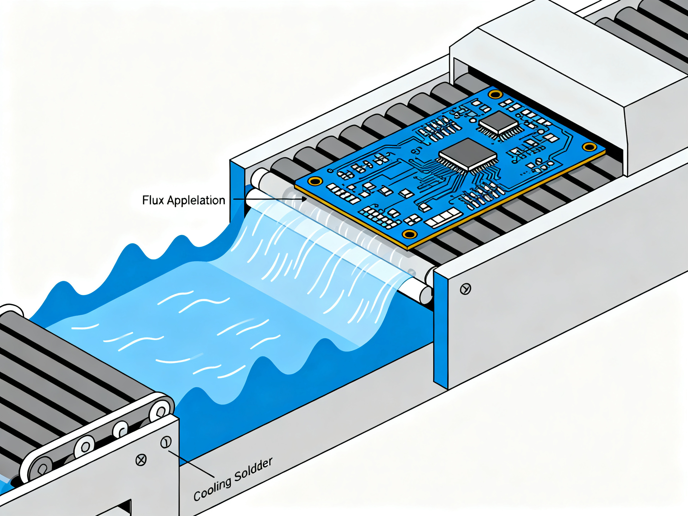
Step 1: Flux Application
Flux hits the board first. It cleans oxides off the metal surfaces and prepares them for solder. Without this step, nothing else matters. The solder simply won’t stick.
Step 2: Preheat
The board travels through the preheat zone. Two things happen here. First, solvents in the flux evaporate, leaving the active chemicals behind. Second, the board temperature rises gradually, which prevents thermal shock when it hits the molten solder. Too fast and components crack. Too slow and the flux burns off before its job is done.
Step 3: The Solder Wave
The board crosses the wave. Molten solder touches the bottom, gets forced up through holes by the wave dynamics, and forms joints on contact. How long this takes, how hot the solder is, and how high the wave sits all determine the quality of what happens next.
Step 4: Cooling
The board exits and cools. Solder solidifies. Joints set. Too fast and the joint cracks. Too slow and you’ve wasted time.
Parameter Interaction Matrix
| Parameter | Affects Wetting | Affects Bridging | Affects Hole Fill | Affects Solder Balls | Affects Component Stress | Affects Throughput |
|———–|—————–|——————|——————-|———————|————————|——————-|
| Preheat Temp | Yes (flux activation) | Yes (burnout risk) | Yes | Yes | Moderate | Low |
| Conveyor Speed | Yes (dwell time) | Yes | Yes | Moderate | Yes | High |
| Solder Temp | Yes (viscosity) | Moderate | Yes | Yes | Low | Low |
| Wave Height | Moderate | Yes | Yes | Yes | Low | Low |
| Board Angle | Moderate | Yes | Moderate | Yes | Low | Low |
| Flux Density | Yes | Yes | Yes | Moderate | Low | Low |
This matrix matters because it shows you can’t tune one thing without touching three others.
The Cause-and-Effect Reality
Here’s the deal. Too little preheat and your flux doesn’t activate properly. The result is poor wetting, cold joints, and solder balls scattering across the board.
Too much preheat and your flux burns off before it reaches the wave. Now you’ve got clean surfaces sitting around getting oxide contamination. Bridging follows because the solder doesn’t know where to stick.
Slow conveyor speed gives you longer dwell time. Sounds good for heat transfer, right? But now you’re holding components at temperature longer. Sensitive parts suffer. And if preheat was aggressive, flux exhaustion kicks in during that extended exposure.
Fast conveyor speed cuts dwell short. Solder doesn’t have enough time to wet properly. Holes don’t fill. Joints look okay but test bad.
Wave height too low means insufficient contact. The solder can’t get into holes properly. Skip defects appear. Wave height too high floods the board. Bridges everywhere.
The Process Window Reality
There is no magic number. There’s a window where everything works together.
For lead-free SAC305 in 2026, that window typically looks like this:
- Solder pot: 255 to 265 degrees Celsius
- Preheat topside: 100 to 150 degrees Celsius
- Conveyor speed: 1.0 to 2.5 meters per minute
- Dwell time: 3 to 6 seconds
- Wave height: Half to two-thirds of board thickness
Inside this window, your settings interact predictably. Outside it, defects cascade.
The trick isn’t finding the perfect single setting. It’s finding the combination that keeps everything in balance for your specific board design, your components, and your production volume.
And that balance shifts based on what you’re building. A thin consumer board needs different settings than a thick automotive module. Mass matters. Component sensitivity matters. Even the surface finish on your pads changes what works.
This is why generic recipes fail. They’re built for imaginary average boards. Your boards aren’t average.
Savjet stručnjaka: Start from supplier datasheets and process windows, then narrow settings using test boards rather than copying a generic profile. The datasheet tells you where to start. Your test boards tell you where to land.
Next, we’ll look at how these parameters are actually calculated so you can set them up correctly from the beginning.
How Wave Soldering Parameters Are Determined
Before you touch a single knob on your wave soldering machine, you need to gather information. A lot of it. This step gets skipped way too often, and it always comes back to haunt you.
The inputs fall into several buckets. First, you need to know your PCB. That means thickness, copper weight, thermal mass, and surface finish. A 1.6mm consumer board behaves completely differently than a 3.2mm automotive module. Copper weight changes how heat spreads. Surface finish matters because OSP, ENIG, and HASL LF all wet differently with lead-free solder.
Next up, your component mix. What through-hole parts are you soldering? How thermally sensitive are they? Some components can’t handle more than 5 seconds above their rating. Others are beefy connectors that need serious heat to fill their holes properly. The hole-to-lead ratio affects capillary action, which directly impacts whether you get proper fill.
Then there’s your quality standard. Are you building to IPC Class 1, 2, or 3? Automotive work probably needs IATF 16949 compliance. Aerospace or military? You’re looking at MIL specs and strict documentation requirements. The required quality standard shapes every decision from here on out.
Here’s a quick checklist of what you need before setting anything:
Inputs Needed Before Setting Wave Soldering Parameters
- [ ] PCB thickness (mm)
- [ ] Copper weight (oz/sq ft)
- [ ] Surface finish type (HASL LF, OSP, ENIG, Immersion Ag)
- [ ] Component thermal sensitivity data
- [ ] Hole-to-lead ratio for through-hole parts
- [ ] Solder alloy selection (SAC305, Sn-Cu, etc.)
- [ ] Flux type and chemistry
- [ ] Pallet use (yes/no, and if yes, thermal impact)
- [ ] Target IPC class (1, 2, or 3)
- [ ] Industry-specific requirements (IATF 16949, MIL specs, etc.)
- [ ] Previous thermal profiling data (if available)
Once you have these inputs, you pull baseline parameters from multiple sources. Your solder supplier datasheet gives you temperature ranges for the alloy. Your flux supplier specifies activation temperatures and spray volumes. Your machine manufacturer documents its capabilities and limits. IPC standards (specifically IPC J-STD-001 for process and IPC-A-610 for acceptability) define what good looks like and how you get there.
PCB design constraints matter here too. If your board has heavy copper pours or large thermal planes, they suck heat away fast. You’ll need more aggressive preheat. If you’ve got a mix of SMT and through-hole, the thermal profile gets more complicated.
Savjet stručnjaka: Start from supplier datasheets and process windows, then narrow settings using test boards rather than copying a generic profile. The datasheet tells you where to start. Your test boards tell you where to land.
From these inputs and baselines, you develop your process window. This isn’t a single number. It’s a range that accounts for normal variation. For lead-free SAC305 in 2026, you’re typically working within these rough boundaries:
| Parameter | Typical Starting Range |
|———–|———————-|
| Solder Pot Temp | 255 to 265 degrees C |
| Conveyor Speed | 1.0 to 2.5 m/min |
| Preheat (Topside) | 100 to 150 degrees C |
| Dwell Time | 3 to 6 seconds |
| Wave Height | Half to two-thirds of board thickness |
These ranges are your starting point. You validate them using test boards, thermal profiling, first-article inspection, and cross-sectioning when needed. Cross-sections let you see actual hole fill and joint structure, which tells you if the parameters actually work for your specific board.
The process window development flows like this: inputs gathered, baseline parameters established, test boards run, results measured, window narrowed, and finally documented settings ready for production.
This validation step separates manufacturers who get it right from those who keep troubleshooting the same defects week after week.
How Wave Soldering Parameters Are Calculated and Set
Now comes the math part. But don’t worry, it’s basic division and you’ll have a calculator.
The key relationship here is this:
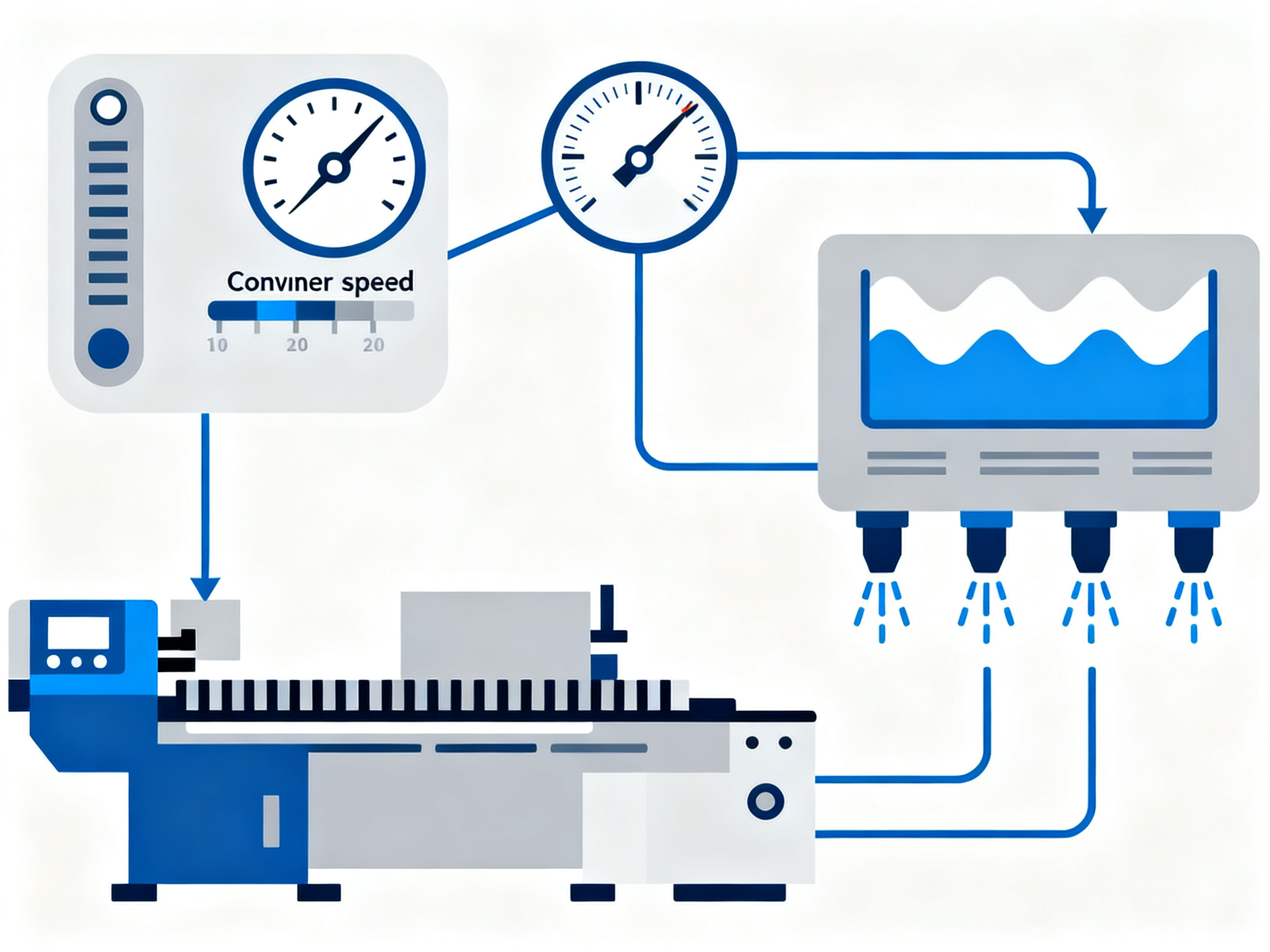
Contact Time (Dwell) = Wave Contact Length ÷ Conveyor Speed
Your wave contact length is basically how wide the wave is where it touches the board. Most machines have a contact zone around 3 to 5 centimeters wide. Conveyor speed is how fast the board moves through, measured in centimeters per second or meters per minute.
Here’s a practical example. Say your wave contact zone is 3 centimeters and you want 4 seconds of dwell time.
3 cm ÷ 4 seconds = 0.75 cm/second
Convert that to industry standard units and you’re looking at about 1.2 meters per minute. That’s a solid starting point for lead-free work.
But wait, you also need to factor in heat exposure. The board absorbs heat from three sources: the preheat zones before the wave, the molten solder itself, and the time spent in the wave. A thick board with heavy copper needs more heat input than a thin consumer board. Your solder temperature, preheat profile, and dwell time all work together to get the job done.
Savjet stručnjaka: Start from supplier datasheets and process windows, then narrow settings using test boards rather than copying a generic profile. The datasheet tells you where to start. Your test boards tell you where to land.
The Calculation Table
Here’s how to set up your initial parameters:
| Parameter | Formula or Method | Example Value | Acceptable Range | Adjustment Note |
|———–|——————|—————|——————|—————–|
| Dwell Time | Contact Length ÷ Conveyor Speed | 4 seconds | 3 to 6 seconds | Longer for thick boards |
| Conveyor Speed | Contact Length ÷ Target Dwell | 1.2 m/min | 1.0 to 2.5 m/min | Slower increases heat input |
| Solder Pot Temp | Set per alloy type | 260°C | 255 to 265°C | Increase for poor wetting |
| Preheat (Topside) | Target based on flux type | 130°C | 100 to 150°C | Higher activates flux better |
| Flux Spray Volume | Per supplier spec | 45 psi | 40 to 50 psi | More for complex boards |
| Wave Height | Half to 2/3 of board thickness | 5 mm | 4 to 7 mm | Adjust based on results |
These numbers are your starting point, not your gospel.
A Real Setup Example
Let’s say you have a 1.6mm mixed through-hole PCB. It has some power connectors and some signal pins. Using SAC305 lead-free solder.
Your wave contact length measures 3 centimeters. You need good hole fill on those connectors, so you target 4 seconds of dwell time.
Working the math:
3 cm ÷ 4 s = 0.75 cm/s = 1.25 m/min conveyor speed
That’s your starting speed. Now set your solder pot to 260 degrees Celsius for SAC305. Set your topside preheat to 130 degrees. Your wave height should be around half to two-thirds of 1.6mm, so roughly 1mm above board contact.
Flux spray volume depends on your flux supplier specs, but 45 psi is a common starting point for foam fluxers.
Now comes the important part. You run test boards. You measure actual temperatures with thermocouples. You cross-section joints to check hole fill. You adjust one variable at a time.
See bridging? Try reducing wave height by 0.5mm or speeding up the conveyor by 0.2 m/min.
Poor hole fill? Slow the conveyor slightly or bump preheat up 10 degrees.
Solder balls showing up? Increase preheat to get more solvent burnoff before the wave hits.
The calculations get you in the ballpark. The test runs get you to the finish line.
And here’s the thing about that 2mm bump we mentioned at the start. The machine probably had the settings right. Someone just didn’t account for solder pot level dropping over a shift or wave height drift from dross buildup. That’s maintenance, not math. But both matter.
What Wave Soldering Parameters to Use for Different PCB Types
Not all boards are created equal. A thin consumer board and a chunky automotive module need completely different approaches. Here’s how to match your settings to what you’re actually building.
Single-Sided Through-Hole Boards
These are the simplest setups. You’re probably running consumer products, maybe some IoT devices. Thermal mass is low. Conveyor speeds can be faster, around 2.0 to 2.5 m/min. Lower preheat is fine, maybe 110 to 130 degrees Celsius topside. Your main worry is getting good hole fill without wasting heat on parts that don’t need it.
Mixed-Technology Boards
Now things get interesting. You’ve got SMT components on top and through-hole parts below. The thermal profile gets complicated because the reflowed solder underneath affects how the board handles the wave.
These boards need slower conveyor speeds, usually 1.2 to 1.8 m/min. Preheat needs to be gentler to avoid disturbing those SMT joints. And your flux application matters more because you’ve got multiple finishes potentially on the same board.
Thick High-Copper Boards
Heavy copper pours and thick substrates soak up heat fast. You need more preheat, slower conveyor speeds, and longer dwell times to get the solder to wet properly. Think 1.0 to 1.5 m/min conveyor speed and 130 to 150 degrees Celsius topside preheat. Sometimes you push the solder pot temperature higher too, toward 265 degrees Celsius for SAC alloys.
The hole fill becomes critical with thick boards. Low preheat plus fast speed equals cold holes every single time.
Connector-Heavy Assemblies
Big connectors mean big thermal mass. Those pins need serious heat to fill properly. But the housing around them might have plastic that can’t take as much. It’s a balancing act.
Slow your conveyor down. Add nitrogen if you can. Use a more active flux to help wetting along. And watch your wave height closely. Too low and the connector holes won’t fill. Too high and you flood the whole assembly.
Selective Pallet Applications
When you’re wave soldering only certain areas of a board, pallets change everything. They block heat transfer and create weird thermal profiles. You might need to slow down the line and bump preheat up to compensate for what the pallet blocks.
Also check your pallet condition regularly. Warped or worn pallets create gaps that let solder splash where it shouldn’t.
The Setup Comparison
Here’s a quick reference for what matters most depending on your board type:
| PCB Type | Priority Setting | Main Risk | Inspection Focus | Optimization Tip |
|———-|—————–|———–|—————–|—————–|
| Single-Sided Through-Hole | Conveyor Speed | Solder balls | Hole fill percentage | Speed up for throughput |
| Mixed Technology | Preheat Control | Disturbed joints | SMT joint integrity | Match to reflow profile |
| Thick High-Copper | Solder Temperature | Cold holes | Barrel fill | Increase pot temp 5-10°C |
| Connector-Heavy | Dwell Time | Poor fill, overheating | Pin saturation | Add nitrogen enrichment |
| Selective Pallet | Preheat Compensation | Leaking, incomplete | Edge coverage | Check pallet condition daily |
High-Reliability Applications
Automotive, aerospace, military, and semiconductor work follow stricter rules. IPC Class 3 is the baseline. That means tighter process windows, more documentation, and stricter inspection.
For automotive work under IATF 16949, you need detailed records of every parameter for every board type. Preheat temps, conveyor speeds, solder pot temperatures. All logged. All verified.
Aerospace and military add MIL specs on top of IPC requirements. Cross-sectioning of joints becomes part of normal quality checks rather than an exception. You validate your process window with test vehicles before touching production boards.
The good news? High-reliability standards force you to get these parameters right the first time. The documentation overhead is real. But so is the peace of mind when your defect rate stays below 50 DPM.
Pro uvid: The fastest diagnostic sequence for distinguishing flux, preheat, conveyor speed, and wave-height causes of common defects is: start with visual inspection, check your most recent parameter change, then verify with a thermal profile. Most defects trace back to one of three things: a setting that drifted, flux that wasn’t fresh, or a board that sat too long before soldering.
Your specific board type dictates your starting point. But your test runs tell you whether you need to adjust from there.
Common Wave Soldering Mistakes and Solutions
Even with the best parameters dialed in, things go wrong. The key is knowing how to fix them without making things worse.
Here’s the hard truth. Most operators see a defect and start chasing one setting, then another, then another. Before long, they’ve changed twelve things and still have the same problem. Sound familiar?
The trick is a disciplined approach. Work through each defect systematically. Change one thing at a time. Then check your work.
The Diagnostic Sequence That Works
When something goes wrong on the line, here’s how to approach it.
First, look at what actually failed. Different defects point to different problems. A bridge between pads means something pushed too much solder where it shouldn’t go. Solder balls scattered around mean the flux didn’t behave right before contact. Cold holes mean not enough heat got through.
Second, check your most recent change. Did you adjust something in the last hour? That’s usually where the problem lives. Machines don’t just drift without cause.
Third, verify your thermal profile. Run a thermocouple check and compare it to your documented setup. Temperature lies more often than you’d think.
Fourth, look at your materials. Is your flux fresh? Has the solder pot been skimmed recently? Old flux and dirty solder cause half the defects nobody can explain.
Pro uvid: The fastest diagnostic sequence for distinguishing flux, preheat, conveyor speed, and wave-height causes of common defects is: start with visual inspection, check your most recent parameter change, then verify with a thermal profile. Most defects trace back to one of three things: a setting that drifted, flux that wasn’t fresh, or a board that sat too long before soldering.
I learned this the hard way a few years back. We had recurring bridges on a automotive module line. Operator changed wave height, conveyor speed, angle, and solder temperature over two days. Still bridging. Turned out the flux nozzle had a partial clog that nobody checked. Fixed in five minutes once someone finally looked.
The Troubleshooting Reference
Here’s a table to keep handy. It covers the most common defects, what usually causes them, which parameter to check first, how to fix it, and how to verify the fix worked.
| Defect | Likely Cause | Parameter to Check | Corrective Action | Verification Method |
|——–|————-|——————-|——————-|———————|
| Bridging | Wave height too high, slow conveyor | Wave height, conveyor speed | Reduce wave height 0.5mm or speed up 0.2 m/min | Run 5 boards, inspect under magnification |
| Insufficient hole fill | Low preheat, fast speed | Preheat temp, conveyor speed | Increase preheat 10C or slow conveyor | Cross-section 2 sample boards |
| Solder balls | Inadequate preheat, turbulent wave | Preheat, wave condition | Increase preheat, check wave for splash | Visual inspection after cooling |
| Icicles | Low solder temp, steep angle | Solder pot temp, board angle | Increase pot temp 5C, verify 5-7 degree angle | Check joint shape visually |
| Dross buildup | Lack of nitrogen, contaminated pot | Nitrogen flow, pot cleanliness | Increase nitrogen, skim pot immediately | Visual wave surface inspection |
| Disturbed joints | Vibration, premature board movement | Conveyor stability, cooling rate | Check conveyor alignment, slow cooling | Inspect joint surface texture |
The One-Change Rule
Here’s what separates good troubleshooters from the rest. When you find a defect, change only one parameter. Then test. Then decide.
Changing multiple things at once means you never know what actually fixed it. And if it didn’t fix it? You’re lost.
Start with the most likely cause based on the defect pattern. Make one adjustment. Run a small test batch. Check results. Then adjust again if needed.
This takes patience. But it’s faster than the scatter-shot approach in the long run.
Most defects connect back to five root causes. Flux problems, thermal issues, speed mistakes, wave height errors, or contaminated solder. Get good at identifying which of the five it is and you’ve solved 80 percent of your problems before touching a single dial.
How to Optimize Wave Soldering Machine Settings for High-Volume Production
Running wave soldering at scale is a different beast. You’re not tweaking settings for one perfect board. You’re keeping hundreds of thousands of boards consistent across shifts, operators, and solder batches.
What Optimization Actually Means at Scale
Here is the deal. Optimization for high-volume production has three real goals.
First, stable first-pass yield. You want the same good output week after week without constant intervention. Second, low rework rates. Every board that comes back costs money and kills throughput. Third, repeatable settings. What works on Monday morning should work on Thursday night with a different operator.
Sounds obvious. But most manufacturers focus on getting one perfect setup and then wonder why things drift. The goal is a process that tolerates normal variation without producing defects.
Iz našeg iskustva: Why stable repeatability across shifts matters more than chasing a one-time perfect solder joint during setup. A perfect joint means nothing if the next fifty boards fail because someone adjusted a setting and didn’t document it.
Process Control Methods That Work
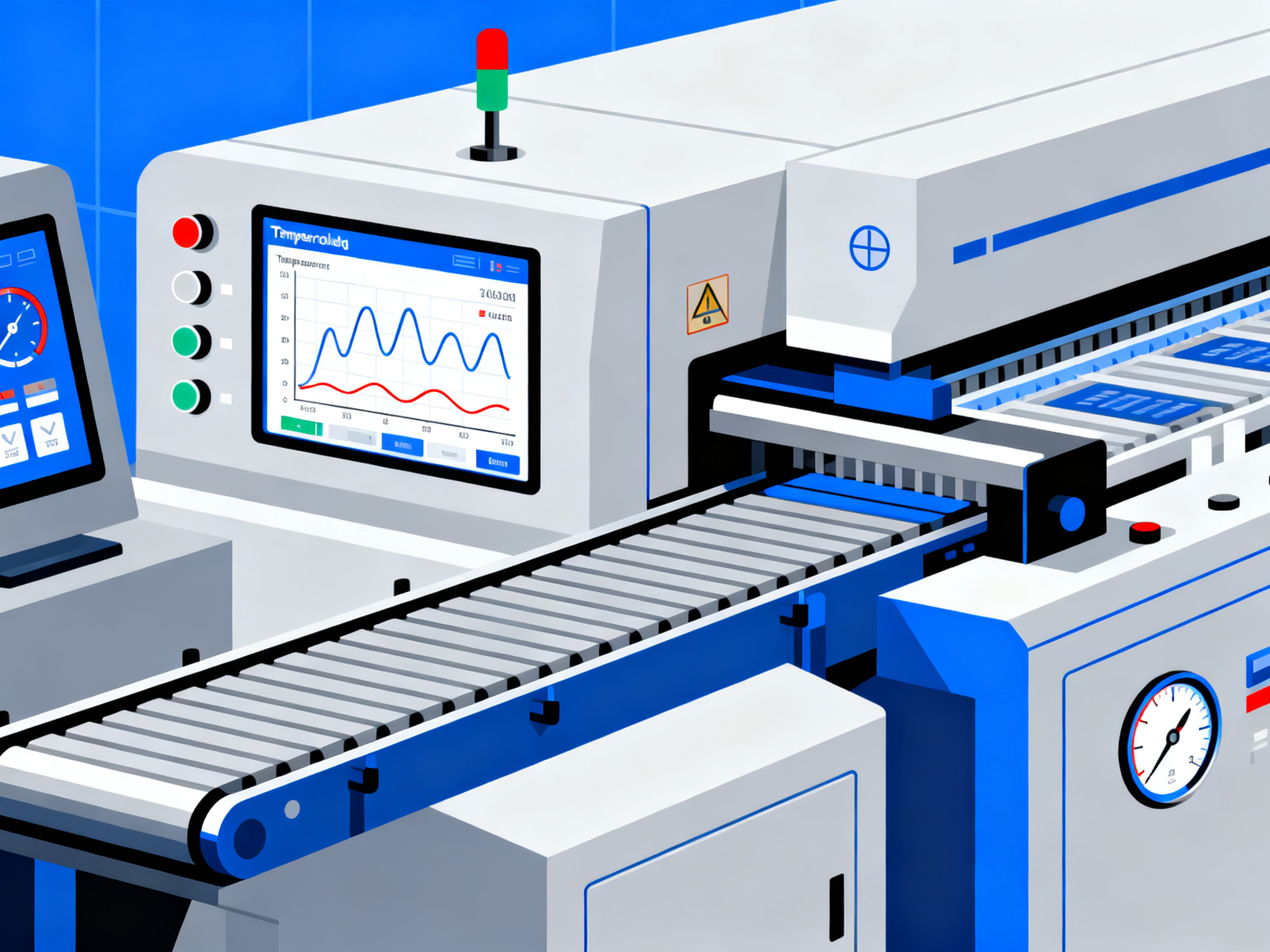
Statistical Process Control (SPC) is your friend here. Track your critical parameters over time with control charts. Conveyor speed, solder pot temperature, preheat readings. When something starts drifting, you catch it before it becomes a defect batch.
Thermal profiling should happen regularly. At minimum, verify your profile when switching board types, after maintenance, or when defect rates change. Many facilities run a thermocouple check every shift change.
Preventive maintenance matters more than most people admit. Skim your solder pot daily to control dross. Clean flux nozzles weekly. Check wave height and angle monthly. These small tasks prevent the drift that causes defects.
Solder analysis is worth doing too. Check your alloy composition periodically. Lead-free SAC305 should stay within 0.5 percent of its specified tin content or the melting point shifts. Flux density needs monitoring as well. Old flux doesn’t clean properly and that’s when wetting fails.
And operator training? Non-negotiable. Make sure everyone understands why the settings matter, not just what the numbers are.
Sample Optimization Workflow
- Establish baseline parameters from supplier datasheets and IPC guidance
- Run test boards and measure actual defect rates
- Implement SPC tracking on critical parameters
- Conduct weekly parameter audits
- Perform monthly preventive maintenance checks
- Review quarterly data to identify drift patterns
- Update recipes with engineering change control
The KPI Table You Need
Track these numbers consistently. They tell you when something is drifting before your defect rate tells you.
| KPI | Target Range | Action When Off |
|—–|————–|—————–|
| First-Pass Yield | Above 98% | Investigate recent changes immediately |
| Defect Rate | Below 0.5% | Check SPC charts for parameter drift |
| Rework Hours | Below 2 hours per shift | Review defect patterns by type |
| Solder Usage | Consistent across shifts | Verify wave height hasn’t changed |
| Dross Rate | Monitored and logged | Increase maintenance frequency if rising |
| Uptime | Above 90% | Schedule maintenance during low-volume periods |
Recipe Management for Production
Lock your approved recipes once validated. Write-protect them in your machine software so operators cannot change settings without authorization. This single step prevents most drift-related defects.
But you need a process for engineering changes too. When a new PCB design comes in, run a validation batch. Test 20 to 50 boards at the approved settings. Inspect and cross-section if needed. Only after passing inspection do you create a new approved recipe.
Component substitutions require the same rigor. A different connector with a different thermal mass might need slower conveyor speed or higher preheat. Don’t assume. Test it.
The documentation burden is real, especially for automotive IATF 16949 or aerospace work. But it pays for itself when you can trace any defect back to its root cause in your records.
For manufacturers running S&M wave soldering equipment or similar systems, the programmable recipe storage makes this straightforward. Save profiles by board type, lock them for production, and verify before unlocking for engineering changes. Automation compatibility also means your line can switch between product families without operator error.
Stable production isn’t about perfect settings. It’s about controlled variation within acceptable limits. Get that right and your defect rate stays low without constant babysitting.
Wave Soldering Parameter Documentation and Compliance
Why does paperwork matter so much in wave soldering? Here’s the thing. Your machine settings are only as good as your ability to prove they were right.
Documentation serves three key audiences. Procurement managers need records to show equipment investments paid off and meet customer requirements. Production heads need proof that processes stay consistent across shifts and operators. Technology officers need data to approve changes and demonstrate compliance during audits.
Without proper records, you’re flying blind when something goes wrong. A defect batch shows up and you have no idea if the solder temperature was correct three hours ago. Did anyone change the recipe last week? Nobody documented it.
What to Keep On File
Here’s what actually matters to document:
- Approved recipes for each PCB type
- Flux batch numbers and dates
- Solder alloy certificates of analysis
- Thermal profiling results
- Inspection and test results
- Maintenance logs for the wave solder machine
- Operator changes to settings
- Engineering change approvals
This creates a paper trail showing what happened, when it happened, and who did it. For lead-free processes, this gets even more critical because your parameters are tighter. A 5-degree shift in solder temperature that wouldn’t matter for tin-lead can cause defects with SAC305.
Industry Requirements Vary
Different industries have different demands. Automotive work under IATF 16949 requires detailed process records and full traceability. Aerospace and military add MIL specs on top of IPC standards. Semiconductor manufacturing often has the strictest requirements of all.
Most facilities struggle with documentation in two ways. They either document too little (only what auditors ask for) or they document too much in the wrong places (scattered files that don’t tell a coherent story when you need them).
The fix is simple. Document what helps you run your business AND satisfy auditors. Modern wave soldering equipment from S&M includes programmable recipe storage with electronic records that make this straightforward. You lock approved recipes, operators follow them, and everything gets logged automatically.
When customers come calling for your quality records, having organized documentation becomes your competitive advantage.
Expert Recommendations for Setting Wave Soldering Parameters
Here’s the core principle that ties everything together. Wave soldering parameters are determined by your board design, materials, component thermal limits, solder alloy, flux chemistry, machine capability, and quality requirements. Every setting flows from these inputs. Get the inputs right first, and the parameters almost set themselves.
The practical sequence is this:
- Establish a baseline from supplier datasheets and IPC guidance
- Calculate dwell time and thermal exposure requirements
- Validate with test boards using thermal profiling and cross-sections
- Troubleshoot by defect pattern, changing one thing at a time
- Lock a documented process window with approved recipes
That’s the path from guesswork to controlled production.
Your next step is to evaluate whether your current wave soldering machine supports the process control, repeatability, and lead-free optimization that 2026 demands.
Final Equipment Checklist
Before signing off on your process, verify these capabilities:
- [ ] Solder pot temperature control within plus or minus 2 degrees Celsius
- [ ] Programmable recipe storage with lock protection against unauthorized changes
- [ ] Nitrogen inerting support for lead-free SAC alloys
- [ ] Conveyor speed consistency verified across shifts
- [ ] Parameter logging for compliance documentation
If you answered no to any of these, your defect rates probably won’t improve until your equipment catches up. Modern wave soldering equipment from companies like S&M addresses these exact gaps with tighter thermal control, automated recipe management, and built-in process documentation.
Jace Liu’s practical recommendation is simple. Invest in equipment that matches your process requirements, not just your current budget. The cost of consistent defects, rework hours, and customer rejects almost always exceeds the upgrade price.