
Published: 25 May 2026
Reading Time: 12 minutes
Reviewer: Simon Scrapes, Founder
Introduction to Advanced Reflow Oven Setup
Ever wonder why some printed circuit boards come off the line flawless, while others end up in the scrap pile? Spoiler alert: it usually comes down to what happens inside the reflow oven.
Here’s the thing. If you’ve spent any time in electronics manufacturing, you already know that soldering is the backbone of everything we build. But what many people overlook is just how sensitive these processes are to temperature control. A few degrees off here, a ramp rate that’s a bit too aggressive there, and suddenly you’re dealing with cold joints, tombstoning, or voids that will haunt your quality metrics for months.
Reflow ovens are the workhorses of surface mount technology (SMT) production lines. They take your solder paste through a carefully choreographed dance of heating and cooling stages, transforming loose components into permanent, electrically sound connections. But here’s the catch: the oven itself is just the vessel. What really matters is how you configure it.
That’s where reflow oven parameters and temperature profiles come into play. These settings dictate every stage of the soldering process, from the initial preheat through the critical reflow zone and finally to the cool-down phase. Get them right and your yield rates soar. Get them wrong and you’re looking at expensive rework, customer returns, or worse.
In this guide, we’re going to break down exactly how to optimize your reflow oven settings for different applications. We’ll cover the critical parameters that matter most, walk through profile setup step by step, and share real-world troubleshooting tips that come straight from the production floor.
Let’s make sure your next batch comes off the line right the first time.
Understanding Reflow Oven Basics
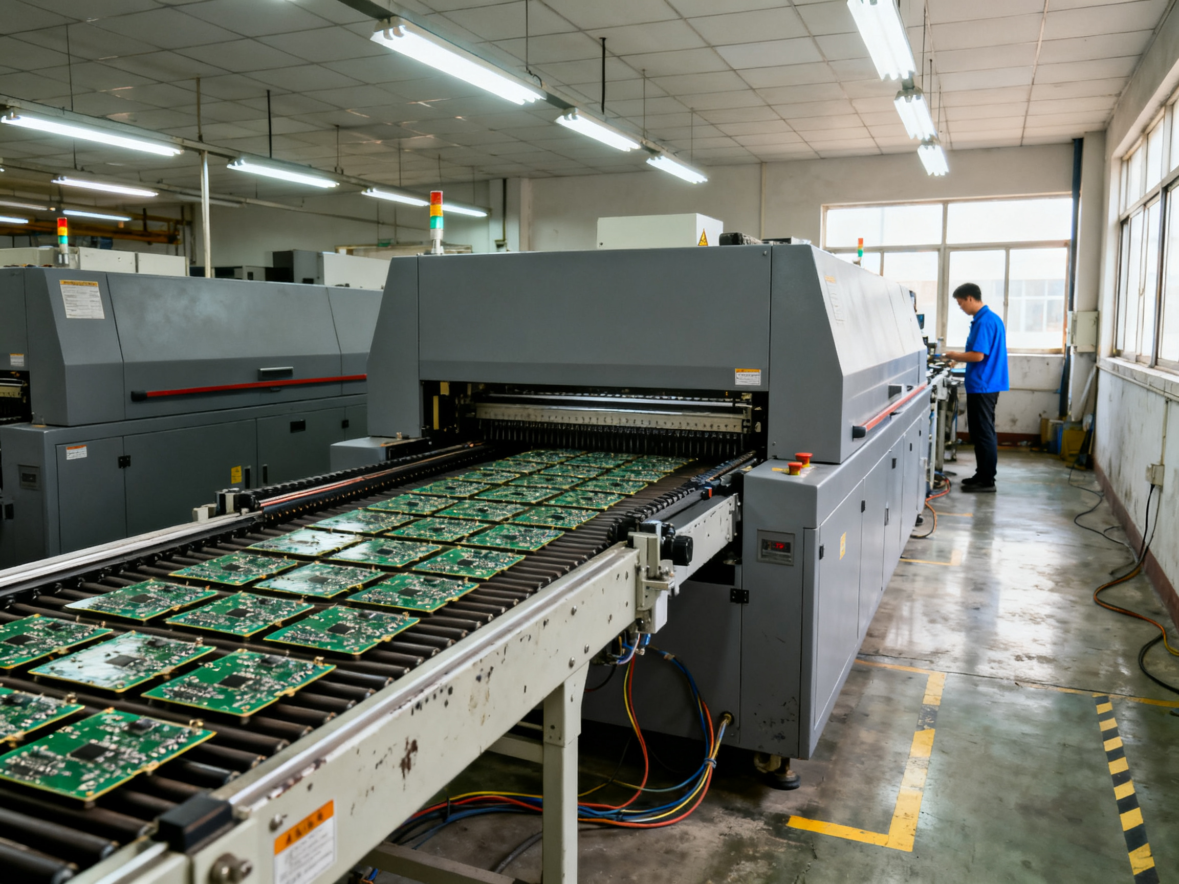
Think of a reflow oven as a carefully orchestrated heating chamber. It’s where your populated PCB board goes in one end and comes out the other with soldered components that are actually going to work.
The process happens in four distinct zones, each with its own job to do.
Preheat Zone
This is where we bring everything up to speed gradually. We’re talking ramp rates somewhere between 0.5 and 3 degrees Celsius per second. The goal? Get the board warm enough to activate the flux without shocking components with sudden temperature changes. Too fast and you’ll crack ceramic capacitors or cause thermal stress in BGAs. Too slow and you’re burning cycle time. Most boards hit somewhere around 120 to 150 degrees Celsius before moving on.
Soak Zone
Also called the thermal equilibrium zone. Here we hold the temperature steady to let the entire board soak at a uniform temperature. This drives off volatiles from the flux and ensures no cold spots exist before we hit peak heat. Typical soak temps land between 150 and 200 degrees Celsius, lasting anywhere from 60 to 120 seconds depending on board complexity.
Reflow Zone
This is where the magic happens. Peak temperature ranges from 235 to 260 degrees Celsius for lead-free solder, high enough to fully melt the solder particles and create proper wetting. The time above liquidus, that critical window where solder stays molten, typically runs 30 to 90 seconds. Get this wrong and you’re looking at cold joints or incomplete reflow.
Cooling Zone
We drop the temperature at a controlled rate, usually 2 to 4 degrees per second. Too fast and you get thermal shock. Too slow and your productivity tanks. The goal is a gradual solidification that minimizes stress on the joints.
Here’s what many people miss: these zones don’t exist in isolation. They flow into each other, and changes in one directly affect the others. A sluggish preheat will compress your soak time. An aggressive ramp to peak temp can blow right past proper wetting windows.
Modern reflow ovens in 2026 handle everything from simple consumer gadgets to aerospace assemblies. A smartphone factory might run 10,000 boards a day through the same oven model that an aerospace contractor uses for 50 high-reliability assemblies per week. The principles stay the same. The parameters get tuned to match.## Critical Reflow Oven Parameters
Now we are getting to the stuff that actually matters. You have got your zones dialed in, but without the right parameters running them, you are just guessing.
Ramp-Up Rates
This is where a lot of setups go sideways. The ramp-up rate controls how quickly your board climbs from preheat to soak temperature. We are talking somewhere between 0.5 and 3 degrees Celsius per second depending on what you are building.
Ramp too fast and you will crack ceramic components or leave the flux undercooked. Go too slow and you are burning cycle time for no good reason. I usually start in the middle, around 1.5 to 2 degrees per second, and adjust based on what I see on the board.
Thing is, the ideal ramp rate depends heavily on your board’s thermal mass. Thin consumer boards can usually handle 2 to 3 degrees per second. Thick multilayer assemblies with heavy ground planes need the gentler 0.5 to 1 degree per second approach. There is always a trade-off between speed and safety.
Pro Insight: Choosing accurate ramp-up rates for defect-free soldering means matching your board’s thermal mass. Thinner boards can typically handle faster ramps, while thick multilayer assemblies need a gentler approach. The goal is consistent temperature distribution across the entire surface without shocking sensitive components.
Peak Temperature
The peak temperature you set determines how hot things get at the hottest point in the reflow zone. For lead-free solder in 2026, you are usually looking at 235 to 260 degrees Celsius. Leaded solder gets by at 210 to 235 degrees.
Why does this matter so much? Because peak temp directly affects solder wetting and flow. Too low and the solder will not melt properly. Too high and you risk damaging components or creating intermetallic issues that weaken joints over time.
I have seen factories chase their tails for weeks trying to fix cold joints when the real problem was peak temp set 10 degrees too low. Also watch your temperature spread across the board. Even 5 degrees difference between thermocouples can cause inconsistent results.
Conveyor Speed
Your conveyor speed dictates how long the board spends in each zone. Faster speed means higher throughput, but less time for thermal processes. Slower speed gives more time but kills your productivity numbers.
Most reflow ovens in 2026 run conveyor speeds between 20 and 100 centimeters per minute. The sweet spot depends on your board size, component density, and the solder profile you are trying to hit.
Here is the thing nobody tells you: conveyor speed and your temperature zones work together. You cannot adjust one without affecting the others. Speed up the conveyor and you compress your zones, which means you need higher temperatures or longer dwell times to compensate.
Most manufacturers provide datasheets for their solder paste that include recommended profiles. Use those as your starting point, then fine-tune based on actual results from your line.
| Parameter | Leaded Solder | Lead-Free Solder |
|———–|—————|——————|
| Peak Temperature | 210-235C | 235-260C |
| Recommended Ramp-Up Rate | 1-3C/s | 0.5-2.5C/s |
| Time Above Liquidus | 30-60 seconds | 60-90 seconds |
| Typical Conveyor Speed | 60-90 cm/min | 50-80 cm/min |
| Cooling Rate | 2-6C/s | 2-4C/s |
Notice the lead-free column requires higher peak temps and longer time above liquidus. This comes from the physics of tin-silver-copper alloys. They melt at higher temperatures than traditional tin-lead solder and need more thermal energy to achieve proper wetting Kester reflow profile comparison.
Also keep in mind that uneven heat distribution remains one of the most common issues in reflow ovens. Factors like inconsistent airflow, differences in PCB thermal mass, and improper sensor placement can amplify temperature problems CircuitNet configuration guide. If you are seeing defects that cluster in specific areas of your board, heat distribution should be your first suspect.
Tailoring Profiles to Lead-Free Soldering Requirements
Here’s where things get more interesting in 2026. Lead-free soldering isn’t optional anymore. Environmental regulations across the EU, Asia, and North America have basically made it the standard. RoHS compliance is now just part of doing business, which means your reflow oven profiles need to handle lead-free alloys properly.
The problem? Lead-free solder melts at a higher temperature than the old tin-lead stuff. We’re talking SAC305 and similar tin-silver-copper alloys that need peak temperatures around 245 to 260 degrees Celsius to reflow correctly. That’s 20 to 30 degrees hotter than what you got away with before.
This matters because those higher temps put more stress on your components. Some older parts weren’t designed for lead-free processes, and you can guess what happens when you push them through a profile they weren’t built for. We ran into this issue with a batch of connectors last year that started delaminating after reflow. Turns out the plastic housings had a max temperature rating of 250 degrees, and our profile was hitting 255. Lesson learned.
So how do you set up profiles that work with lead-free without cooking your components? First, pay attention to your time above liquidus. Lead-free needs longer dwell times at peak temperature, usually 60 to 90 seconds, to get proper wetting. Shorter than that and you get incomplete reflow, especially on larger pads.
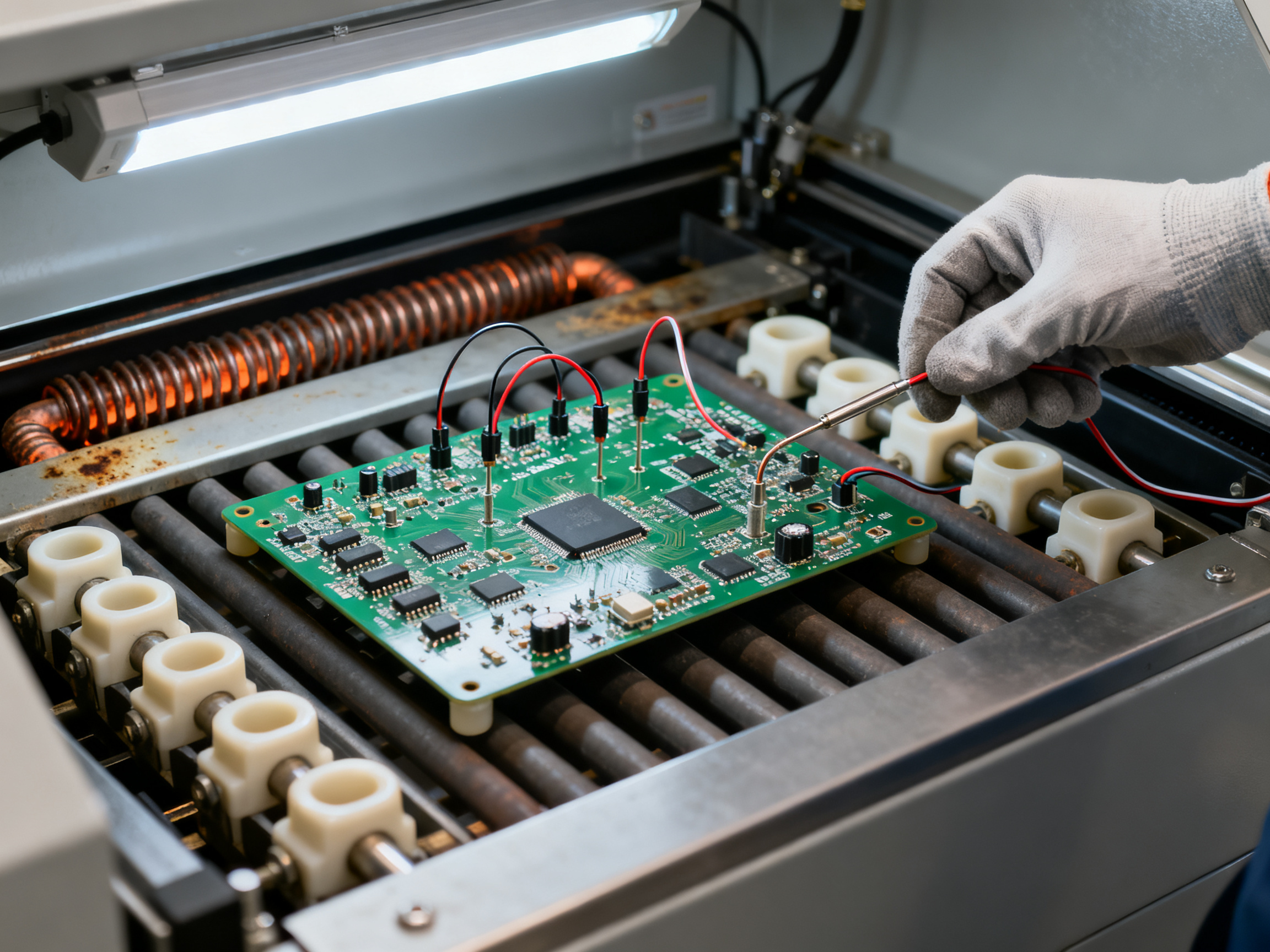
Second, your ramp rate strategy changes. You want something gentler during preheat, around 1 to 1.5 degrees per second, to avoid活化 the flux too early. Then your soak zone should be tighter and hotter, around 180 to 200 degrees for 60 to 90 seconds. The goal is getting uniform thermal distribution before you hit peak heat.
Minimizing voiding in lead-free joints is another big concern. Voids happen when flux solvents get trapped under the solder during reflow. They weaken joints and can cause field failures. To cut down on voiding, we typically drop the cooling rate to around 1.5 to 2 degrees per second. It slows down solidification just enough to let volatiles escape.
Also, check your nitrogen atmosphere settings if your oven supports them. Inert gas environments reduce oxidation during reflow, which improves wetting and cuts down on void formation. Most high-end reflow ovens in 2026, including models from manufacturers like Shenzhen Chuxin Electronic Equipment Co., Ltd., offer nitrogen capability for this exact reason. The trade-off is higher operating cost, but for mission-critical assemblies in aerospace or automotive, it’s usually worth it.
Expert Tip: Overcoming challenges in lead-free soldering compliance starts with knowing your components. Always check the thermal rating of the most sensitive part on your board before setting peak temperature. And don’t forget that your board thickness affects the profile too. Thick boards need lower conveyor speeds or higher temps to achieve the same thermal transfer as thin boards.
The soak zone deserves extra attention for lead-free. You want enough time there to bring the entire board to equilibrium before reflow. Skip this step and you’ll get uneven heating, which shows up as tombstoning on small chip components or shifted BGAs. We usually validate soak effectiveness by checking that all thermocouples read within 5 degrees of each other before the profile moves into reflow.
Finally, document everything. Once you nail a profile for a specific board, save it with the revision and date. You do not want to be hunting through settings trying to recreate a profile that worked six months ago when you are already behind on a production run.
Advanced Troubleshooting Techniques
Even the best reflow oven setup will give you headaches eventually. The trick is knowing how to figure out what’s wrong fast, before a small problem turns into a production nightmare.
Diagnosing Thermocouple and Profiling Issues
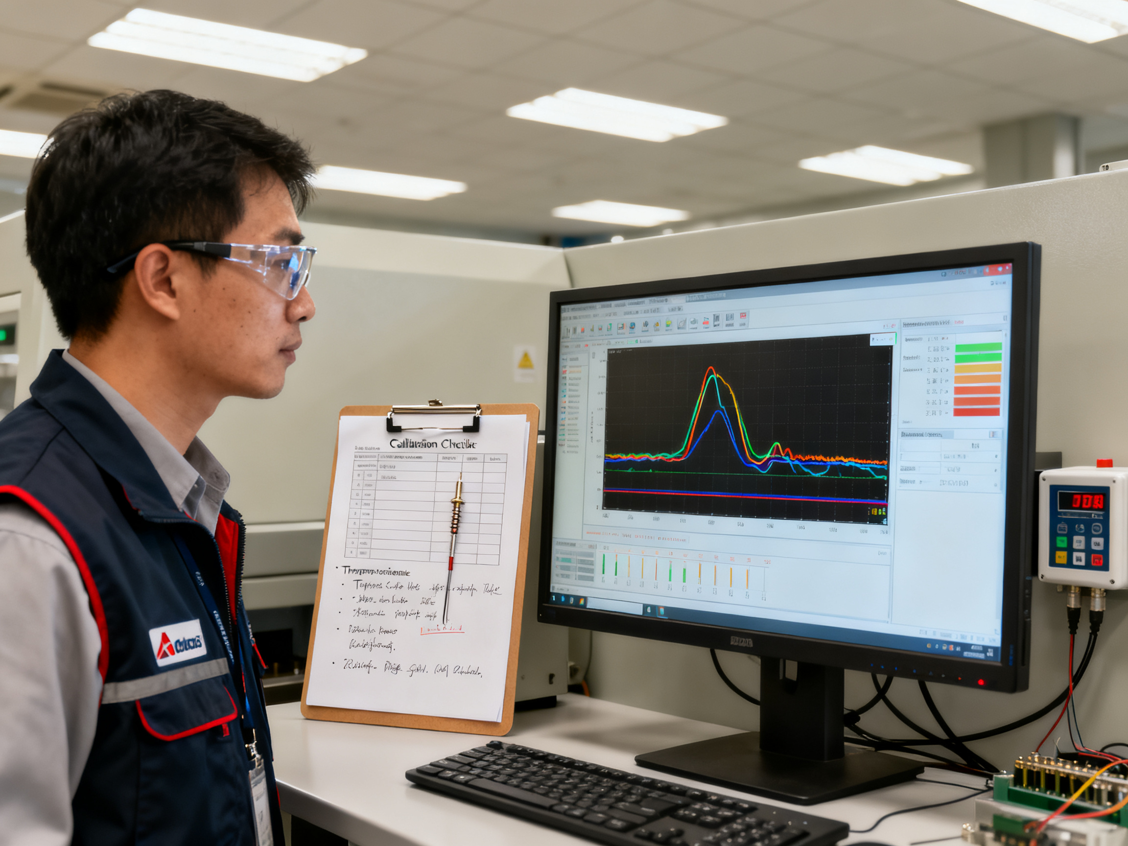
Thermocouples drift. It’s just a fact of life in thermal processing. After months of repeated high-heat cycles, your sensors start reading off by a few degrees here and there. That drift compounds into profile drift, which shows up as inconsistent results across production runs. Regular calibration checks help catch drift before it impacts product quality.
Profiling software gives you real-time visibility into what’s actually happening inside the oven. These tools let you map temperature across the board surface, identify hotspots and cold spots, and validate that your actual profile matches your intended profile. Without this data, you’re basically guessing whether the oven is performing correctly.
Common thermocouple problems include wire degradation, connector corrosion, and incorrect placement. If your measurements seem off, swap sensors to isolate the problem. Also check that your profiling software is using the right thermocouple type for your application. Type K is most common, but Type T works better for lower temperature ranges.
From Our Experience: We had a customer running automotive assemblies who started seeing intermittent opens on BGA components. Initial assumption was component quality. But after pulling data from their profiling software, we found their peak temperature was dropping 8 degrees Celsius over the course of each shift as the heating elements fatigued. The fix was straightforward: replace the thermocouples and recalibrate the heater control loop. Sometimes the obvious answer is the right one.
Solving Overheating and Cold Solder Joint Issues
Cold solder joints are trickier than overheating. They often trace back to insufficient time above liquidus or peak temperature that’s too low. We’ve seen cases where a board with heavy ground planes needs 15 degrees higher peak temp than a lighter board to achieve the same wetting. The solution involves either adjusting the profile or pre-heating the board in a separate oven to reduce thermal demand during reflow.
Overheating issues usually show up as darkened solder mask, component discoloration, or delaminated pads. If you see these symptoms, check your peak temperature settings first. But also verify your thermocouple placement. Sensors positioned too close to heating elements will read artificially high, causing you to under-shoot your actual board temperature.
Defects like tombstoning and solder balling point to specific profile problems. Tombstoning happens when one side of a component reflows before the other, creating an unbalanced surface tension that stands the part up. This typically means your preheat ramp is too aggressive. Solder balling, where small spheres of solder form away from pads, usually indicates moisture in components or flux that activated too early.
Uneven heat distribution remains one of the most common issues in reflow ovens. Factors like inconsistent airflow, differences in PCB thermal mass, and improper sensor placement can amplify these problems CircuitNet configuration guide. If you’re seeing defects that cluster in specific areas of your board, heat distribution should be your first suspect.
Tools for Real-Time Monitoring
Modern SMT lines benefit from continuous monitoring systems that track temperature, conveyor speed, and atmospheric conditions in real time. These systems alert operators immediately when parameters drift outside specification, preventing defect escape before the board moves downstream. For high-mix operations, this proactive approach cuts rework costs significantly.
Reflow oven optimization is critical because it directly determines solder joint quality, yield, and long-term reliability in modern electronics manufacturing BTU Applications. Errors in temperature control, oxygen level, or cooling can cause defects like incomplete reflow, voids, tombstoning, and microcracking that haunt your quality metrics for months.
Quick Troubleshooting Checklist
Here is a practical checklist for common reflow oven problems:
- Verify thermocouple calibration and placement
- Confirm peak temperature matches solder paste specifications
- Check time above liquidus stays within recommended window
- Inspect for uneven heat distribution across board surface
- Validate conveyor speed consistency throughout the run
- Review atmospheric conditions if using nitrogen inerting
- Cross-reference actual profile against intended profile using profiling software
- Monitor for recurring defect patterns that suggest systemic issues rather than random variation
When in doubt, run a bare board through with thermocouples attached. This gives you actual temperature data at component locations rather than relying on estimated values. Most profiling systems in 2026 make this straightforward, and the data is worth every minute spent.
Common Reflow Oven Issues and Solutions
| Issue | Likely Cause | Quick Fix |
|——-|————-|———–|
| Cold joints | Low peak temp or insufficient time above liquidus | Increase peak temp by 5-10 degrees or slow conveyor |
| Tombstoning | Aggressive preheat ramp rate | Reduce ramp rate to 1-1.5 degrees per second |
| Solder balling | Moisture in components or early flux activation | Pre-bake boards before assembly |
| Voids | Trapped flux solvents or rapid cooling | Slow cooling rate to 1.5-2 degrees per second |
| Pad damage | Peak temp too high | Reduce peak temp, check thermocouple placement |
| Intermittent opens | Thermal drift over production run | Recalibrate thermocouples, check heating elements |## Common Mistakes to Avoid in Reflow Oven Profile Setups
Let us talk about the stuff that trips up even experienced engineers. Knowing what NOT to do is half the battle, and honestly, it will save you a ton of headaches down the road.
Misaligning Conveyor Speeds with Profile Requirements
This one shows up constantly on production floors. You set up a perfect temperature profile, but then somebody bumps the conveyor speed up to hit throughput targets without adjusting the rest of the settings. Suddenly your boards are flying through the reflow zone too fast. They do not spend enough time at peak temperature. Wetting suffers. Cold joints follow.
The fix? Treat conveyor speed as a linked parameter. Every time you change speed, you need to revisit your temperatures. Faster conveyor means you probably need higher peak temps or adjusted zone lengths to compensate. Slower conveyor means the opposite. Write this relationship into your standard operating procedures so nobody forgets.
Overlooking Preheat and Soak Zone Specifications
I get it. The reflow zone seems like where all the action happens. But the preheat and soak zones do the heavy lifting when it comes to thermal uniformity. Rush these stages and you will pay for it later with tombstoning, voids, or components that simply will not wet properly.
Skipping proper soak time is tempting when you are trying to push more boards through. But without that thermal equilibrium phase, different parts of your board hit peak temp at different times. The result is inconsistent joints across the board, and that variability is a quality nightmare.
Neglecting Regular Maintenance and Calibration
Here is a hard truth. Ovens drift. Thermocouples degrade. Heating elements lose efficiency. If you are not running regular calibration checks, you are essentially flying blind.
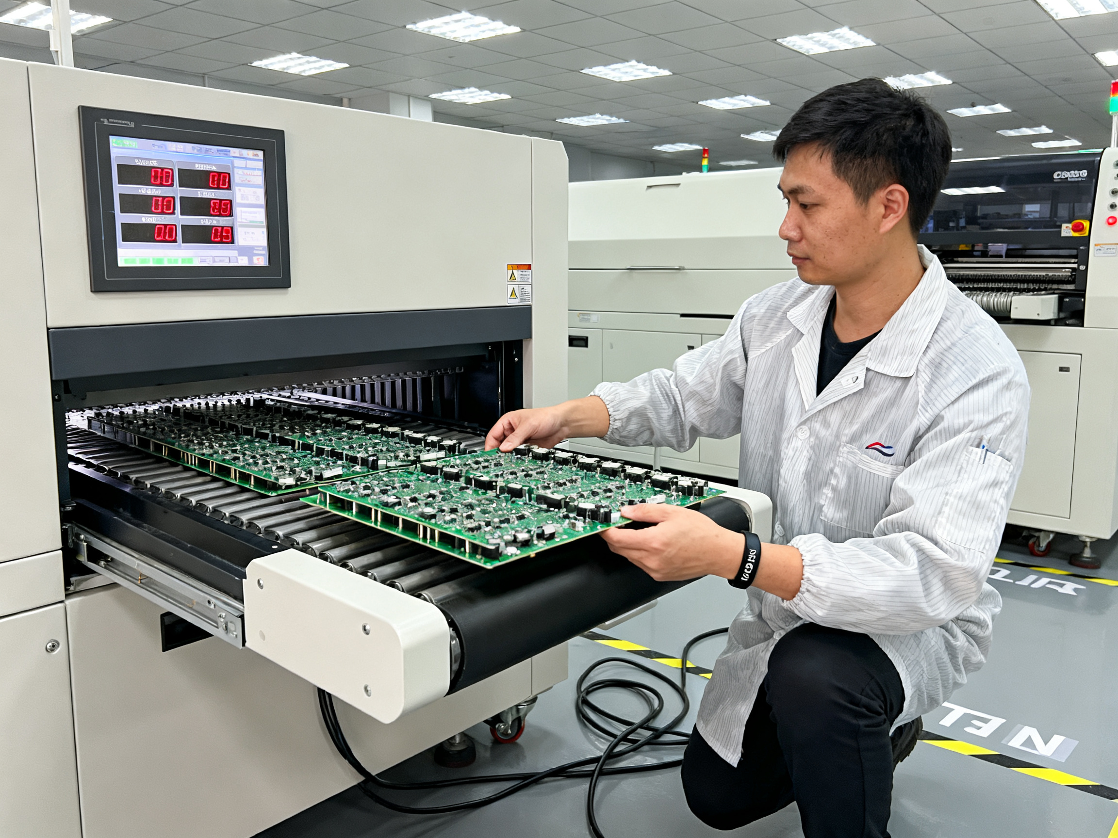
In our experience, shops that schedule weekly thermocouple verification and monthly profile audits have dramatically fewer random defects. It takes maybe 30 minutes per week to run a validation board through. That investment beats spending hours debugging mysterious quality issues or reworking batches that should have been good.
Modern equipment from manufacturers like Shenzhen Chuxin Electronic Equipment Co., Ltd. includes built-in diagnostics that flag drift before it becomes a problem. Use those features. They exist for a reason.
Common Mistakes at a Glance
| Mistake | What Goes Wrong | Prevention |
|———|—————–|————|
| Conveyor speed misalignment | Cold joints, incomplete reflow | Recalculate temps when speed changes |
| Skipping preheat/soak | Thermal non-uniformity, tombstoning | Enforce minimum zone times |
| Skipping maintenance | Profile drift, random defects | Weekly calibration checks |
| Copying profiles without validation | Incompatible thermal mass | Always run test boards first |
The pattern here is straightforward. Profile setup is not a one-time thing. It is an ongoing discipline. Build these checks into your routine and your yield rates will thank you for it.## Future Trends in Reflow Oven Technology
So what is coming next for reflow ovens? If you think the last few years brought big changes, just wait. The technology is heading in some exciting directions, and manufacturers who stay ahead of these trends will have a real edge.
AI is Starting to Show Up
Artificial intelligence is starting to show up in reflow oven control systems, and honestly, it is about time. Modern AI can analyze thermal data from dozens of sensors and automatically suggest profile adjustments based on what it learns from each production run.
Instead of spending hours tweaking settings by trial and error, operators can now let the oven essentially teach itself. Some systems in 2026 already predict drift before it becomes a problem, flagging maintenance needs before you even see a defect on the board. This is a big deal for high-volume operations where a few bad boards can mean thousands in rework costs.
Environmental Compliance Features Get Smarter
Green manufacturing used to be a nice-to-have. Now it is table stakes. Reflow ovens in 2026 come packed with features designed to reduce energy use and minimize waste.
Modern systems reclaim heat from the cooling zone to pre-warm incoming boards, which cuts power consumption significantly over time. Nitrogen consumption gets monitored and optimized too, with closed-loop systems that only use what they need instead of running wide open.
And with regulations tightening globally, ovens are being built to handle the next generation of lead-free and low-temperature solder alloys that manufacturers will need to adopt in the coming years.
Sustainability Starts Paying Off
Beyond compliance, the business case for sustainable oven design is getting stronger. Manufacturers like Shenzhen Chuxin Electronic Equipment Co., Ltd. are building ovens with longer service lives and modular designs that let you upgrade individual components rather than replacing the whole machine.
Smarter thermal management also means less energy wasted and lower operating costs. Some new models include energy monitoring dashboards that show real-time consumption data, helping facilities spot inefficiencies and dial in savings.
The reflow oven of 2026 is a far cry from the basic heaters of a decade ago. With AI optimization, stricter environmental standards, and real focus on efficiency, the industry is moving fast. Companies that jump on these trends now will be better positioned to handle whatever comes next. The writing is on the wall. This stuff matters for staying competitive.## Conclusion and Key Takeaways
OK, let’s bring it all together.
Reflow oven parameters matter more than most people realize. We have spent this whole guide walking through the ins and outs of temperature profiles, zone configurations, and all the little settings that add up to either stellar results or a pile of expensive scrap.
Here is the quick recap of what actually works:
The Big Three Settings
- Ramp-up rate between 0.5 and 3 degrees per second, adjusted for your board’s thermal mass
- Peak temperature of 235 to 260 degrees Celsius for lead-free solder
- Conveyor speed linked to your zone temperatures, not treated as a standalone variable
These three things will solve most of your problems before they even start.
The Best Practices That Make the Difference
- Always validate new profiles with test boards before production runs
- Run weekly thermocouple checks because drift happens to everyone
- Treat preheat and soak zones as essential, not optional stages
- Document your working profiles so you can recreate them later
- Watch for defect patterns that point to systemic issues rather than random problems
Why You Should Care About New Tech
The reflow ovens of 2026 are smarter than they have ever been. AI-powered optimization, predictive maintenance alerts, and energy-efficient designs are no longer luxuries. They are becoming the baseline for competitive manufacturing operations.
Companies still running on manual profile adjustments and reactive maintenance are leaving efficiency on the table. Investing in modern reflow technology, even if it means upgrading equipment, pays off in the long run through better yields and lower operating costs.
At the end of the day, your reflow oven is only as good as the parameters you feed it. Get those right, stay on top of maintenance, and keep an eye on where the technology is heading, and your SMT line will be a well-oiled machine.
That is how you get boards that come off the line right the first time, every time.
Quick Reference: Critical Reflow Oven Parameters
| Parameter | Recommended Range | Notes |
|———–|——————-|——-|
| Ramp-Up Rate | 0.5-3°C/s | Adjust for thermal mass |
| Peak Temperature (Lead-Free) | 235-260°C | Match solder specifications |
| Time Above Liquidus | 60-90 seconds | Critical for wetting |
| Conveyor Speed | 50-100 cm/min | Depends on board size |
| Cooling Rate | 2-4°C/s | Too fast causes thermal shock |
| Soak Temperature | 150-200°C | Ensures thermal uniformity |
| Soak Duration | 60-120 seconds | Drive off flux volatiles |
Bookmark this guide. Tape it to your oven. Whatever works. But please, stop guessing at your parameters and start optimizing.