
PCB Handling Systems for Modern SMT Production
Published: 03 November 2026
Last Updated: 03 November 2026
Reading Time: 15 minutes
Written by:
Reviewed by:
Modern SMT production is often described in terms of placement speed, placement accuracy, feeder performance, and reflow throughput. Those capabilities matter, but a production cell cannot sustain them without a carefully engineered system for moving bare printed circuit boards, component reels, trays, and finished assemblies through the line. Handling failures introduce jams, contamination, ESD damage, moisture-related defects, mix-ups, and traceability gaps. They also consume labor and machine time in ways that are difficult to see from placement-speed metrics alone.
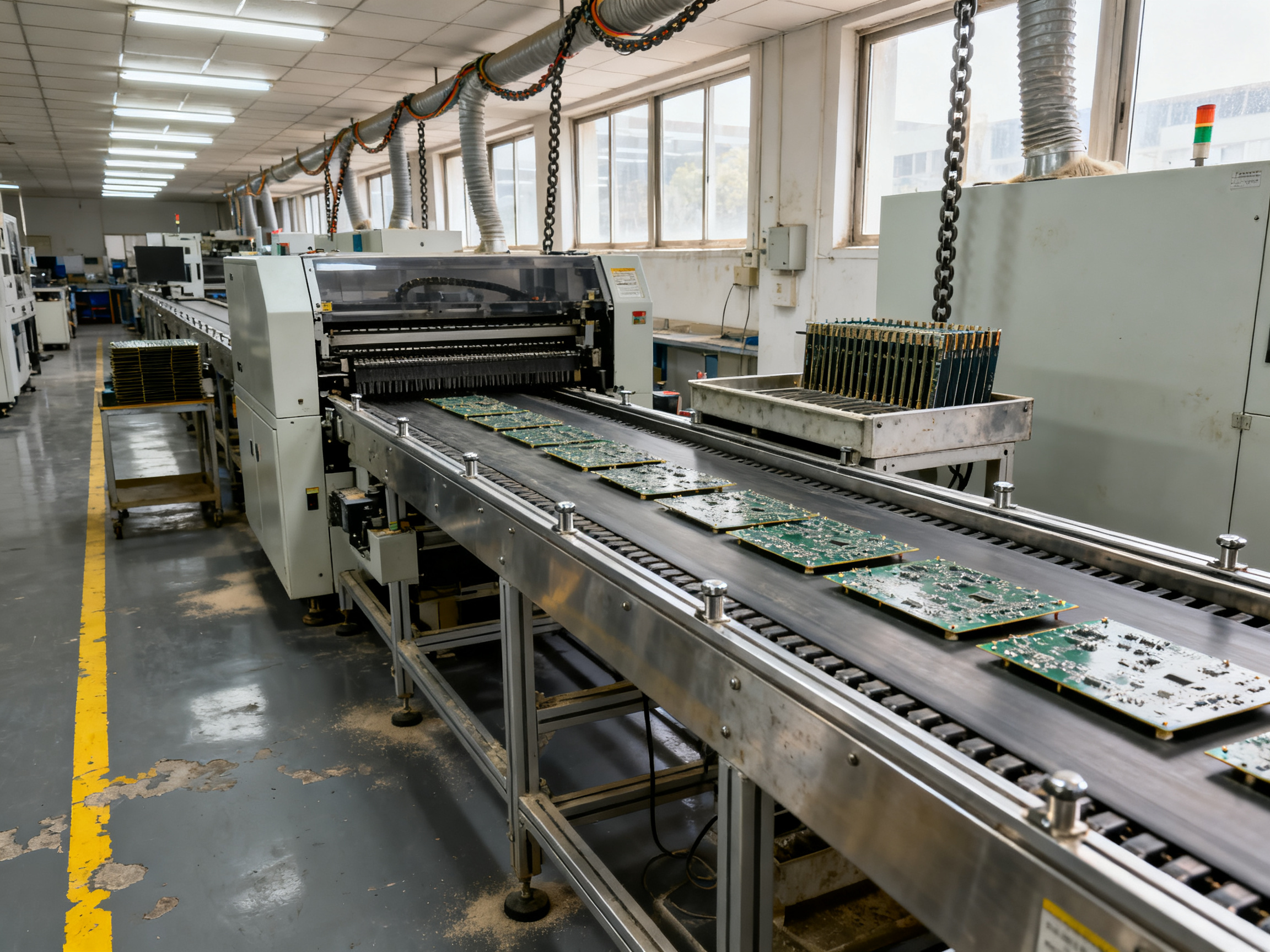
A modern PCB handling system therefore serves as more than a conveyor between machines. It is a controlled material-flow and product-care layer that connects storage, preparation, printing, placement, inspection, reflow, depanelization, testing, and shipment. The right design protects the product, preserves manufacturing data, supports operator safety, and gives the production system a reliable source of work.
What a PCB handling system must accomplish
A practical handling system has several simultaneous objectives. First, it must present each PCB to every process in the correct orientation and at the correct speed. Second, it must prevent physical damage to the board, its pads, components, solder mask, and exposed surfaces. Third, it must control electrostatic discharge risk. Fourth, it must preserve the identity and status of each product as it moves through the process. Finally, it must remain available for maintenance without compromising cleanliness or ESD protection.
These objectives create competing constraints. A narrow transfer mechanism may protect delicate boards but limit throughput. A wide conveyor may improve capacity while collecting debris or making manual access difficult. High-speed indexing can reduce cycle time but increase the force applied during a stop. A fully automated system can improve consistency but require more complex recovery procedures when a board is malformed or a downstream process rejects it.
The design should begin with product and process characterization rather than with a selected conveyor model. Relevant variables include board dimensions, thickness, panelization method, material, surface finish, warpage sensitivity, component height, connector protrusion, bottom clearance, permissible edge contact, contamination risk, required traceability, and cycle time. The same handling principles apply to a high-volume automotive line and a mixed-product medical-device line, but their risk priorities and automation levels will differ.
The material-flow model
A robust SMT line is best understood as a sequence of controlled states rather than a collection of disconnected machines. Although line configurations vary, a common flow includes the following stages:
- Receipt and quarantine of bare boards, components, and assemblies
- Incoming inspection and material-identification verification
- Storage under required environmental conditions
- PCB preparation, including cleaning, inspection, and drying when necessary
- Loading or automatic feeding into the printer
- Solder-paste printing and inspection
- Component placement
- Automated or manual inspection
- Reflow soldering
- Depanelization or routing
- Final inspection, testing, boxing, and shipment
Every transfer between those states needs an explicit control. For example, a panel arriving from the supplier should not move directly into production if its lot identity has not been reconciled with the work order. Likewise, a board rejected by a solder-paste inspection system should be diverted without allowing an operator to return it to the line without an recorded disposition.
A useful flow model defines buffers deliberately. Pre-print buffering decouples board preparation from paste-printer availability. Post-placement buffering allows inspection resources to operate independently of the placement cell. Post-reflow buffering absorbs the thermal and mechanical variation that can occur while solder solidifies. Finished-goods buffers support packing and shipping schedules. Small automatic buffers improve flow, but their capacity should be based on realistic process rates and anticipated downtime rather than on optimistic nominal-machine specifications.
Conveyors, transfers, and mechanical interfaces
The conveyor is the central mechanical element of many SMT lines, but its contact surfaces deserve unusually close attention. Boards normally ride on rails, belts, rollers, pins, nests, or vacuum cups. The selection should account for board flatness, weight, finish, fragility, panel tabs, and tolerance buildup across a large assembly.
Rollers can provide low friction and good thermal separation during reflow, but each roller adds a contact point and a potential source of contamination. Flat belts offer a continuous support surface and can be easier to clean, although belt tracking, seam geometry, and thermal behavior require attention. Chain conveyors support heavy fixtures but may introduce pitch, vibration, and cleanliness issues. Vacuum conveyors avoid distributed mechanical contact and can handle smooth panels, but they require reliable vacuum generation, suitable surface materials, and controls that prevent false retention or loss of vacuum.
Transfer between conveyors is often more damaging than steady transport. A gap at the handoff can allow a board to drop, twist, or catch an edge. Pitch changes can introduce shear. Accumulation conveyors need to accelerate or stop smoothly so that a board does not overshoot its nest. Powered roller sections should be interlocked so that powered and gravity sections cannot move at incompatible speeds.
Gapping is the space reserved between consecutive boards. Its purpose is to permit tooling, paste inspection, optical inspection, nozzle clearance, and operator intervention without collision. Excessively tight gapping can reduce throughput or force equipment to operate outside its intended transfer envelope. Excessively wide gapping increases line length, board exposure, and the number of opportunities for mishandling. Gaps should be derived from machine requirements and verified with the actual board population, including the tallest components and the most fragile panel structures.
Fixtures and nests should locate the PCB repeatably while avoiding stress on sensitive areas. For rigid boards, positive geometric location on low-stress edges may be appropriate. For thin, large, or warped boards, support and vacuum distribution may be needed to minimize handling of flexible circuits. The board manufacturer’s recommended handling and assembly requirements should take precedence over assumptions based only on board thickness.
ESD control through the material-flow system
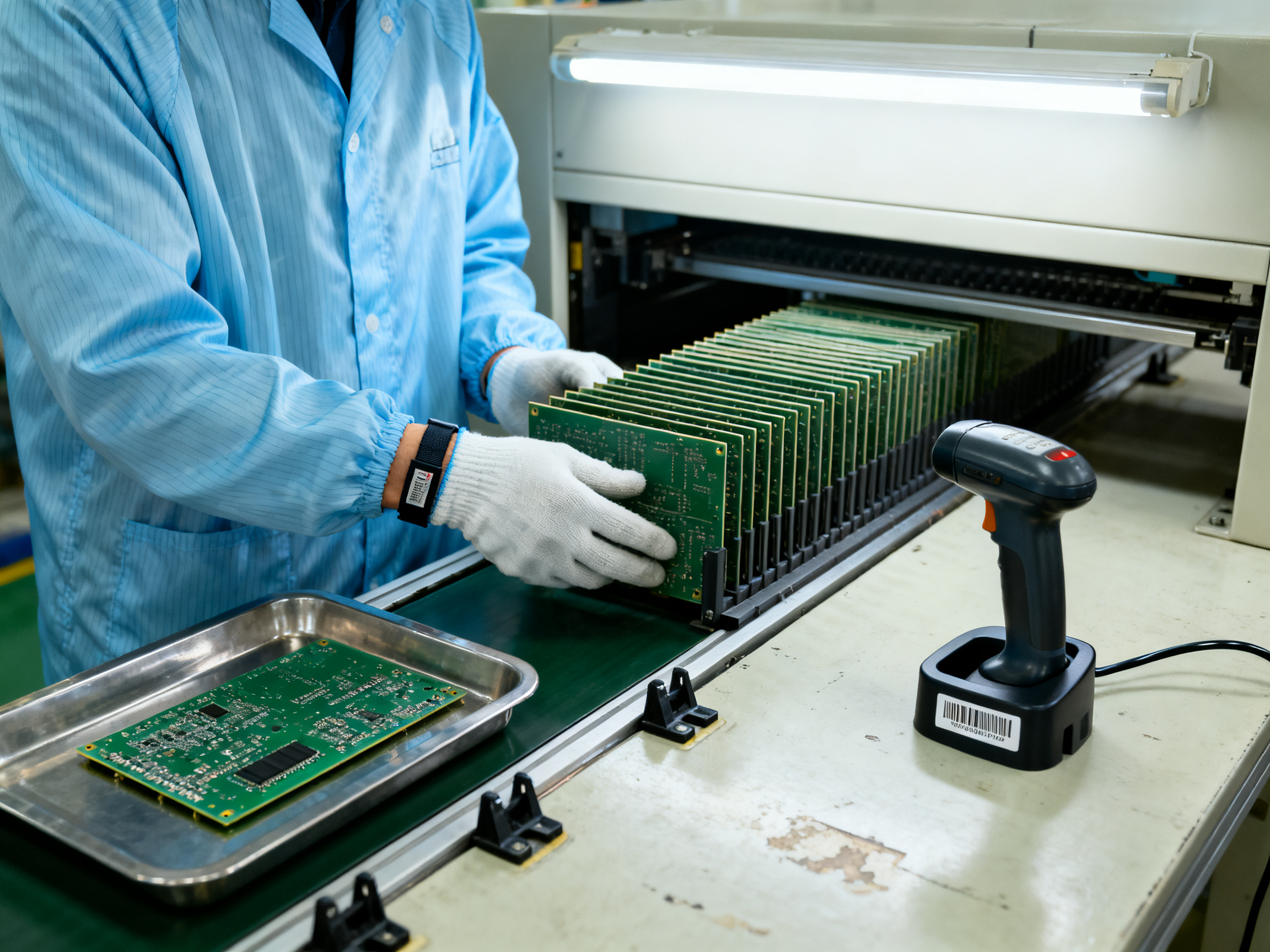
ESD protection is a system requirement, not a property of a single wrist strap or floor mat. The handling system must maintain a controlled electrostatic-program environment from incoming receipt through final packing whenever exposed boards or ESD-sensitive components are present.
The ESD Association’s standards directory is the primary source for industry requirements and test methods associated with ESD-control program elements. The recognized program framework commonly known as ANSI/ESD S20.20 covers grounding, personnel grounding, equipment grounding, EPA shelving, and the handling of parts and equipment in protected areas. Products should be evaluated against the current edition and its referenced test methods rather than against informal descriptions of “ESD-safe” equipment.
For handling-system design, the important questions include:
- Are transport carts, shelves, conveyor frames, and fixtures bonded into the facility grounding system where required?
- Are conductive or dissipative surfaces selected appropriately for the parts they contact?
- Do automated machines have conductive covers, fixtures, and supports with controlled ground-connection points?
- Can an operator reach a defined personnel-grounding point without crossing an unprotected process area?
- Are labels and packaging capable of remaining in place without obscuring product or safety information?
- Are non-grounded items, such as certain handheld tools and cleaning materials, reviewed before entry into the ESD-protected area?
The IEC webstore provides the primary source for IEC standards concerning electrostatic discharge control, including IEC 61340-5-1 for personnel grounding and IEC 61340-2-3 for materials classified by their electrostatic behavior. Applicability and edition selection should be confirmed through the organization’s ESD-control plan and regulatory environment.
A conveyor frame does not automatically become part of the ESD grounding system simply because it is metallic. Paint, anodic coatings, insulating rollers, seams, and poorly designed bonding points can interrupt electrical continuity. Conversely, grounding every object indiscriminately is not a substitute for a documented system. Grounding design should be verified by qualified personnel using appropriate standards-based methods.
Moisture-sensitive devices and bake management
Moisture-sensitive devices require stricter handling than a normal board may require. Devices with moisture-sensitive packaging are assigned shelf-life and exposure conditions by their manufacturers. If the permitted moisture exposure is exceeded, the devices may need baking before use. Baking without proper controls can also create problems through oxidation, package damage, or handling damage.
The handling system should maintain a visible and auditable chain of custody for every moisture-sensitive reel or tray. At minimum, it should record the manufacturer, part number, lot or date code, moisture-sensitivity level, packaging condition, arrival date, opening date, exposure history, bake date, and release status. Where device manufacturers permit vacuum drying or another controlled conditioning method, that process should occur in a qualified facility with calibrated equipment.
For bare PCBs, moisture absorption is particularly relevant when copper is exposed, laminate materials are hygroscopic, or assembly processes involve extended exposure. A board manufacturer may specify a controlled storage and baking procedure. Personnel should not treat a bake oven as a generic drying cabinet. Temperature, duration, airflow, loading patterns, reel and tray spacing, and post-bake exposure controls should follow the applicable component or board supplier’s requirements and the organization’s validated process.
A common weakness in handling systems is the loss of information at a workcell boundary. A reel may be scanned when it reaches the printer and scanned again at the placement feeder, but the two scans may not be linked. The ideal design captures one event when the material is removed from controlled storage and retains that event throughout the flow. The line should be able to answer when a package was opened, where it went, and whether it experienced an uncontrolled delay.
Identification and traceability
Traceability is increasingly important for regulated, safety-critical, automotive, medical, aerospace, and defense-related production. A barcode or RFID system is only useful if it identifies the right object and if its events are associated with the correct product record. For boards and panels, identifiers may include work order, part number, revision, lot, serial number, date code, operator, process, and inspection disposition.
The IPC standards catalog is the primary standards source for electronics manufacturing and assembly requirements, including traceability-oriented standards such as IPC-1782. The organization should determine which edition and scope apply to its products and quality system. A handling system should not be judged only by whether it can read a barcode; it should be judged by whether it can preserve the link among the physical item, its material lot, process history, and final inspection record.
Identity verification should occur at logical boundaries:
- Incoming material is compared with the purchase order and receiving record.
- Boards are verified before loading or after depanelization, depending on how the product is controlled.
- Reels are verified before feeder loading.
- Unique serialized assemblies are verified at final test and packing.
- Nonconforming material is placed in a physically and electronically controlled status location.
A good system prevents a wrong board from being processed. A stronger system also prevents a correct board from losing its history. That means storing identifiers in a way that survives cleaning, thermal processing, abrasion, and normal handling. Label placement must be reviewed with product engineers because a barcode can damage a board if it is applied to a sensitive surface or placed near an area that will undergo reflow, coating, or mechanical stress.
Inspection, diversion, and rework
Inspection is often the point at which a handling system must make a difficult decision. A solder-paste inspection machine may identify a defect, an AOI station may flag a component, or reflow monitoring may indicate a process excursion. If the rejected board travels onward, the apparent benefit of automation is lost.
Rejected PCBs should be diverted to a designated location before or immediately after the relevant process. The rejection mechanism should preserve the association between the board and its defect record. Manual review can then occur without mixing rejected product with good product or with material awaiting rework.
Rework handling requires special care. A board removed from the main flow may be placed into a tray with insufficient support, or it may be carried in a conductive container that is not approved for the product. Components removed during rework must also be controlled according to their status. Rework instructions should define acceptable trays, bags, labels, grounding arrangements, maximum exposure times, and traceability events.
The IPC standards catalog also provides primary access to standards covering soldering and inspection processes, including IPC-A-610, IPC J-STD-001, IPC-A-600, IPC-7711/7721, and IPC-CC-830. The current editions and applicable product classes should be selected by qualified engineering and quality personnel. These documents inform the acceptance and rework decisions that the handling system must support; they do not replace supplier-specific instructions or engineering judgment.
Cleanliness, contamination, and maintenance
Contamination control depends on keeping the handling path clean and preventing foreign material from moving with the product. Open conveyors, exposed cable chains, damaged belts, and poorly maintained transfer points can collect dust, solder particles, flux residue, fibers, and metal debris. The contamination may then be transferred to solder paste, component leads, optical sensors, or final product surfaces.
Cleaning schedules should be based on condition and process requirements rather than only on calendar intervals. During routine line maintenance, personnel should inspect belt surfaces, rollers, rails, vacuum cups, nests, sensors, cable carriers, and product-contact fixtures. Cleaning agents must be compatible with the board surface, solder mask, elastomers, labels, and conductive or dissipative properties. A material that leaves no visible residue can still create an electrical, ionic, or cleanliness problem.
Vacuum systems deserve particular attention because their failure modes are not always obvious. A worn cup may create a vacuum leak; a porous or contaminated cup may retain a board unexpectedly; a failed filter may cause reduced suction. Inspection should include cup condition, filter status, vacuum level, sensor alignment, and release behavior. The equipment should fail safely and provide an alarm that identifies loss of retention or loss of transport control.
Predictive maintenance can improve availability, but only when measurements relate to actual failure mechanisms. Motor current, vibration, temperature, belt tension, vacuum pressure, cycle counts, and jam events can be useful. A dashboard should not treat every alarm as equally important. A low-priority lubrication alert and a jam at the transfer into the reflow oven have very different production consequences.
Safety and operator interaction
Automation can remove ergonomic stress and repetitive handling, but it can also create pinch points, unexpected movements, and maintenance hazards. Risk assessments must consider normal operation, jam clearing, manual loading, inspection, cleaning, power loss, and recovery after a failed interlock. The Occupational Safety and Health Administration is the primary regulatory source for workplace-safety requirements applicable in the United States; local law and site-specific standards must also be considered.
Guards should prevent access to hazardous motion without interfering with routine inspection. Emergency stops should be readily accessible and should not depend on a mobile phone or software interface. LOTO procedures should cover every energy source, including pneumatic pressure, vacuum, gravity, stored mechanical energy, and electrical energy. Maintenance personnel should not have to defeat a safety device to reach a routine adjustment point.
Ergonomics deserve explicit review. Operators should be able to load and unload trays or reels without repeatedly twisting, reaching above shoulder height, or holding a heavy panel away from the body. Work surfaces should support the product rather than forcing an operator to act as a fixture. Assist devices should be selected based on load, repetition, available space, and the risk of introducing product damage.
Human factors also affect quality. A poorly labeled control may cause the wrong mode to be selected. A display that shows only a fault code may force the operator to search for documentation. A product-flow display should make the current state, count, and required action clear, while access to detailed engineering and quality data should be role-controlled.
Automation, controls, and interoperability
Modern SMT equipment commonly communicates through industrial networks and application-specific interfaces. The handling system must exchange the correct signals and data with printers, placement machines, inspection equipment, reflow ovens, and warehouse or execution systems. These signals typically indicate product presence, transfer completion, upstream availability, downstream readiness, jams, and stop conditions.
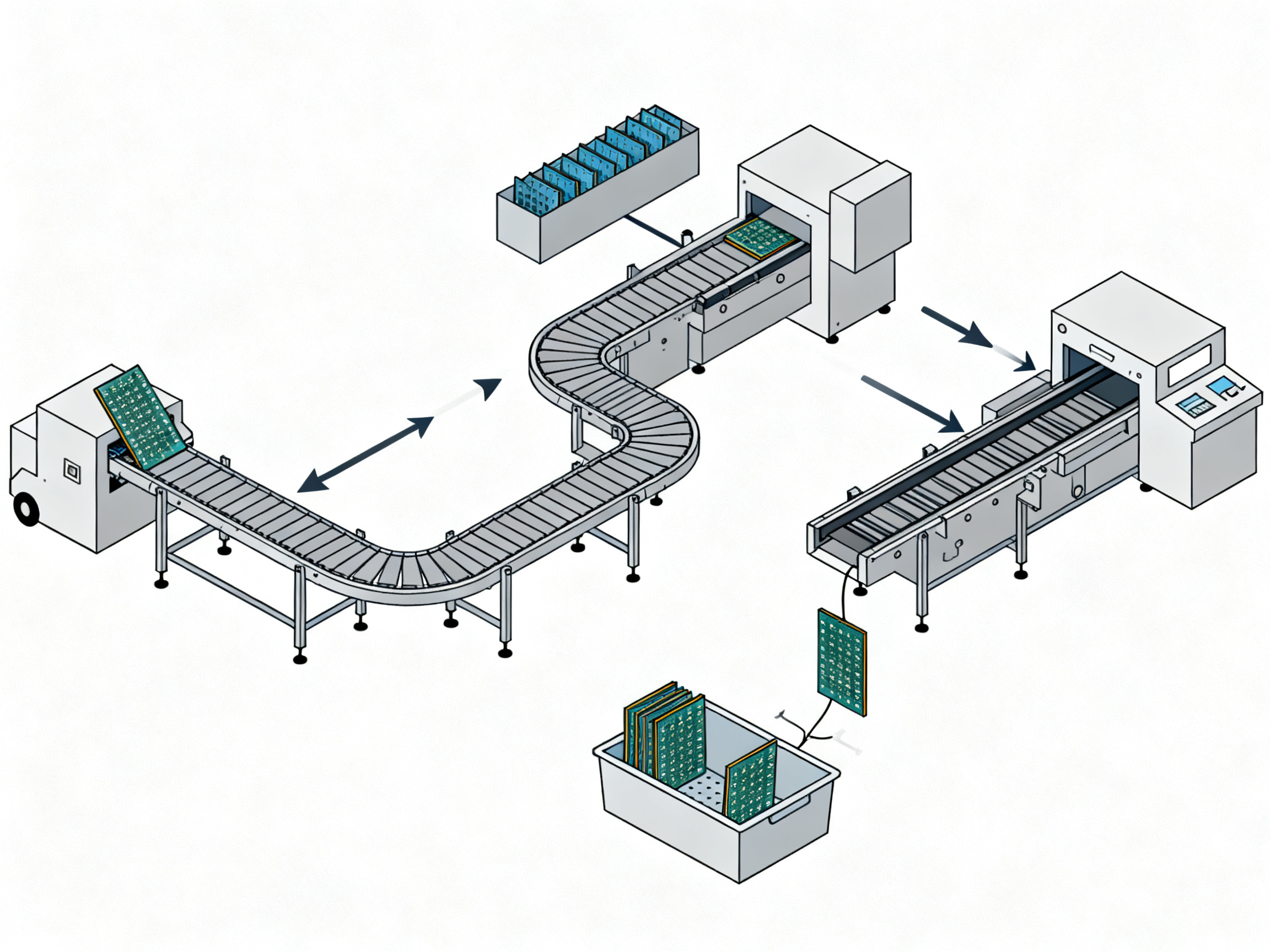
A handling system should not create an uncontrolled buffer merely because two machines occasionally disagree. The PLC logic and production software should define who has control of a board, how a handoff occurs, and what happens if a sensor changes state unexpectedly. Transfer permissions should prevent simultaneous commands that could move a board in opposite directions.
Data integration should preserve semantic meaning. A “board present” bit is not equivalent to a released product record. A location identifier should not be reused for a different lot without an audit event. If the line uses an MES or manufacturing execution system, event timestamps, equipment identities, operator identities, and product identifiers should be synchronized and retained according to the organization’s data-governance requirements.
Cybersecurity is part of operational reliability. Network-connected handling equipment should be inventoried, configured under change control, and protected according to the organization’s industrial-control-system security program. Remote access should be authorized and logged. Default passwords, undocumented service accounts, and uncontrolled software updates can create risks even when the handling system itself uses simple mechanics.
Designing for flexibility without creating complexity
A production environment rarely remains static. Product mix changes, packages are redesigned, lead times move, and a new inspection requirement alters material flow. Handling systems should therefore include controlled points of flexibility: adjustable rail width, configurable gapping, modular conveyor sections, programmable transfer positions, and changeable recipe parameters. Flexibility is valuable only if operators can use it without introducing errors.
A product recipe should define more than conveyor speed. It may need to specify gap settings, sensor enablement, belt or roller configuration, vacuum timing, station routing, reject-bin mapping, identifier verification, and permitted board dimensions. Changeover procedures should identify which parameters are manual, which are downloaded automatically, and which require quality authorization. Unused settings and mechanical adapters should be stored in a controlled way so that the correct configuration can be restored reliably.
Changeovers should also account for the small but consequential details: panel orientation, separator placement, reel labels, tray maps, component sequence, and the location of sensitive components. A scalable design does not eliminate these details; it gives the line a consistent method for managing them.
Validation and process qualification
Handling equipment should be validated in the context of the complete process. It is not enough to demonstrate that a conveyor can move a good board. Validation should include intended products, acceptable process variation, foreseeable misloads, jam conditions, sensor failures, power loss, communication loss, and operator recovery.
The ISO standards catalogue provides the primary source for international management-system standards. ISO 9001 addresses quality-management-system requirements, while ISO 13485 applies to medical-device quality-management systems. ISO/IEC 17025 addresses testing and laboratory competence. For information-security and supply-chain programs, organizations may also consider ISO/IEC 27001 and ISO 28000. Applicability should be determined by the organization and its regulatory obligations.
For regulated markets, the applicable regulatory framework must also be identified. In the United States, the U.S. Bureau of Industry and Security regulations are the primary source for export-control rules administered through the EAR. Trade-compliance controls may restrict where certain products, software, technology, or technical data can move. Handling-system software should not silently connect to a prohibited destination or expose controlled manufacturing data to an unauthorized system.
Validation evidence should demonstrate not only initial installation but also continued control. Spare parts, firmware updates, mechanical adjustments, sensor replacement, and software changes can alter process behavior. A change-control plan should define when requalification is required. Calibration tools and reference standards should be traceable to suitable national or international standards, and maintenance records should connect performed work to the affected equipment version.
Performance metrics
Throughput is an obvious handling-system metric, but it should not be treated in isolation. Useful indicators include:
- Good panels per hour
- Machine utilization attributable to handling
- Mean time between jams and mean time to recover
- Percentage of automatic transfers requiring manual intervention
- First-pass yield after loading and unloading
- Number of wrong-product or missing-identifier events
- ESD, moisture, damage, and contamination-related deviations
- Average changeover time by product family
- Storage and in-process inventory by material state
- Buffer occupancy and starvation events
Cycle time should be measured at defined points so that queues and hidden waiting are visible. A high average conveyor speed can still produce poor output if the system repeatedly stops for inspection, feeder shortages, or identification failures. Conversely, reducing speed slightly may improve first-pass yield and overall equipment effectiveness if it prevents defects and reduces interruptions.
The metrics should promote system improvement rather than encourage local optimization. A station team should not be rewarded for maximizing its own speed if that causes upstream starvation, downstream accumulation, or handling damage. End-to-end metrics reveal where additional buffering, process improvement, training, or capacity is actually needed.
Implementation roadmap
A modern handling-system upgrade is most successful when it is staged around product risk and operational evidence. A practical roadmap can begin with documentation and basic controls, progress to physical improvements, and then add automation where the data supports the investment.
- Map the current flow. Record every transfer, queue, identifier event, failure mode, manual intervention, and environmental requirement.
- Classify products and risk. Identify fragile, moisture-sensitive, high-value, regulated, high-mix, and contamination-sensitive items.
- Correct immediate product-control gaps. Add suitable trays, labels, grounded shelving, reject locations, exposure records, and changeover instructions.
- Stabilize mechanical reliability. Inspect conveyors, transfers, fixtures, sensors, vacuum equipment, and guarding before increasing automation.
- Standardize identifiers and events. Define the identifier hierarchy, scan points, audit trail, and rules for quarantine and release.
- Integrate controls and execution systems. Standardize handshake logic, data ownership, downtime reasons, and recipe management.
- Validate and qualify. Test normal production, edge cases, recovery, cleaning, maintenance, and change control using defined acceptance criteria.
- Monitor and improve. Use meaningful operational metrics to refine buffer sizes, changeovers, maintenance tasks, and training.
This sequence recognizes that automation cannot compensate for an undefined material flow. The most effective systems make the correct action easy, make the incorrect action difficult, and leave a reliable record of what happened.
Conclusion
PCB handling is an integral part of SMT production, not ancillary equipment placed between unrelated processes. It controls how products enter the line, how conditions are maintained, how identity is preserved, how defects are contained, and how finished goods leave the factory.
The strongest modern handling systems share several characteristics. They are designed around actual product risk. They use standardized interfaces for mechanical support, ESD control, moisture management, identification, inspection, and rework. They treat conveyors and buffers as part of a production-control architecture. They fail predictably when sensors, networks, or operators intervene, and they provide enough auditability to reconstruct material history.
As SMT lines become faster, more automated, and more data-rich, handling-system design must become more disciplined rather than simply more complex. Throughput matters, but so do damage prevention, process stability, operator safety, and traceability. A successful system does not merely carry a PCB from one machine to another. It ensures that every PCB arrives at the next operation in the condition required for a good product—and that the organization can prove it.> Published: 03 November 2026
Reading Time: 15 minutes
Written by: [Author name]
Reviewed by: [Reviewer name, credentials]
Introduction: Why PCB Handling Is a Production-Critical Process
A board riding down a conveyor looks like nothing is happening. Then check the output at the end of the shift. Lifted pads on a BGA. A scratch across the solder mask. A reject nobody can trace back to a reel. Almost every one of those started as a handling problem, not a placement problem.
Here is the thing most lines get wrong. They measure the printer, the placer, and the reflow oven, then treat the conveyor as hallway space. But scratches, contamination, electrostatic discharge (ESD), and warpage all come from how the product is touched, supported, buffered, and stored. Fix those and you cut rework. Ignore them and no amount of placement speed will save the shift.
The stakes in 2026 are higher than they used to be. Lead-free reflow runs hotter, so boards flex more. Fine-pitch BGA and QFN parts hide defects that older processes got away with. And the parts that fail from ESD are often tiny ones. The 2024 edition of IEC 61340-5-1 covers components rated as low as 100 V human body model and 200 V charged device model, which is why the current IEC ESD standard applies to so much of what we handle.
This guide covers the whole flow: conveyance, transfer between machines, buffering, storage, and the operator procedures around all of it. The goal is simple. Get every PCB to the next operation in the condition that process needs, and keep the record of how it got there.
flowchart LR
    A[Loading] --> B[Conveyance]
    B --> C[Buffering]
    C --> D[Inspection]
    D --> E[Unloading]
    E --> F[(Storage)]
    F --> A
    D -- Reject --> G[(Hold / Rework)]
[Author name] is [verified role or credential] with [verified experience] in SMT equipment, PCB production, electronics manufacturing, or process engineering. [Add one verified achievement, certification, project, or measurable result directly related to PCB handling, ESD control, line integration, or production quality.]### About the Author
[Optional author headshot]
[Author name] is [job title / credential] with [number] years of experience in SMT equipment, PCB production, electronics manufacturing, or process engineering.
[Add one verified achievement directly related to PCB handling, line integration, ESD control, soldering quality, or high-volume production. Examples of the kind of detail readers trust: a line conversion that cut changeover time by X%, an ESD program audit pass, a defect-rate reduction on fine-pitch BGA work, or a project that integrated conveyors, buffers, and inspection into a single validated flow.]
Every handling guideline in this guide is written from a production perspective rather than a theory perspective. That means the recommendations favor what has been proven on a working line, including the tradeoffs, the failure modes, and the things that look fine right up until a shift change.
Have a question about a specific handling problem on your line? Send it through the contact form. Questions about conveyors, trays, storage, ESD control, and transfer procedures get answered directly by the author, usually with a suggested next step and the standard that applies.
[Optional: author profile link, LinkedIn, or professional headshot placeholder]## 1. What Is PCB Handling and How Do PCB Handling Systems Work?
PCB handling is the controlled movement of bare boards and populated assemblies through production. That covers more than sliding a board down a belt. It includes orientation, buffering, protection from damage and static, storage, and keeping the record of where each board has been.
So how do PCB handling systems work? They work as a chain of linked stations. A loader feeds boards onto a conveyor or a shuttle. Sensors confirm the board is present and identify it. The board moves through a buffer so one slow machine does not starve the next. A turn unit rotates panels to the correct angle. At the end, an unloader sends good boards to storage and bad ones to a reject area. Software coordinates the whole chain through standard machine-to-machine signals, such as the Hermes interface standard for SMT line communication.
flowchart LR
    A[Loader / Magazine] --> B[Transfer Conveyor]
    B --> C[Buffer]
    C --> D[Turn Unit]
    D --> E[Process Station]
    E --> F[Inspection / Reject]
    F --> G[Unloader]
    G --> H[(Storage)]
The level of automation changes how much of that chain a person runs.
| Factor | Manual Handling | Semi-Automated Handling | Fully Automated Handling |
|—|—|—|—|
| Throughput | Low, tied to operator speed | Medium, operator loads and unloads | High, continuous flow |
| Labor | High, constant attendance | Medium, attended at load points | Low, exception handling only |
| Consistency | Varies by person | Good with standard work | Very good, repeat by recipe |
| Traceability | Manual records, easy to miss | Scans at key points | Automatic event capture per board |
| Investment | Low | Medium | High |
Manual handling still fits prototypes, rework benches, and low-volume mix. Semi-automated systems suit most mid-volume lines. Full automation pays off with stable volume and repeatable product families.
Expert Tip: Specify handling equipment as part of the complete SMT process, not as a separate conveyor purchase. A conveyor picked on its own will not match the pitch, height, and handshake your printer and placement machine actually need. Buy it as one system and the transfer problems mostly design themselves away.
Where should you start? Write down what your line carries today, how much a jam costs per hour, and where boards get damaged. That list tells you whether the first fix belongs in conveyance, storage, or control software.
Questions about matching handling equipment to your SMT line? Send the details and the author will reply with a suggested next step.## 2. The Main Risks When Handling PCBs
Most PCB handling problems do not announce themselves. A board comes off the line and looks fine. Then AOI flags a lifted pad, or the customer finds a corrosion issue six months later. Handling is usually the cause, even when the failure shows up much later.
Here is the pattern I have seen most often on working lines. An operator pulls a panel from a magazine, sets it down on the edge of a workbench, reaches for a marker, and writes the lot number on the solder mask. Nothing dramatic happens that day. But a marker stroke on a solder-mask surface plus a fingerprint plus a panel that was flexed while being lifted equals a reject three days later at final test. Every one of those small habits was invisible on the line.
Risk matrix for PCB board handling
| Hazard | Stage affected | Likely defect | Detection method | Prevention control |
|—|—|—|—|—|
| Electrostatic discharge | Storage, loading, feeder setup | Dead or damaged ESD-sensitive components, especially tiny BGA and QFN parts | Failure analysis, device test | Grounded EPA, wrist straps, grounded trays and racks |
| Particulate and ionic contamination | Printing, placement, reflow | No-clean residue, dendrites, solder balls | Ionic contamination test, AOI, cleanliness test | Covered trays, filtered air, cleaned conveyors |
| Moisture exposure | Storage of bare boards and opened reels | Delamination, oxidation, reduced solderability | Solderability test, bake records | Controlled storage, MSL floor-life tracking, bake procedure |
| Fingerprints and oils | Manual loading, inspection | Poor solderability, ionic residue | Visual, ionic test | Gloves, clean work surfaces, defined handling points |
| Abrasion and scratches | Conveyor transfer, tray stacking | Damaged solder mask, exposed copper, broken traces | Visual, AOI | Edge-only contact, protective tray liners |
| Bending and flexing | Panel handling, magazine loading | Cracked vias, barrel cracks, delamination | Cross-section, AOI | Support under components, multi-point support for thin boards |
| Vibration and impact | Transport between lines, packing | Solder joint cracking, dropped board damage | In-process test, visual | Shock-rated packaging, secure stacking |
| Component damage | Placement and post-placement transfer | Bent leads, cracked ceramics, missing parts | AOI, X-ray | Fixture clearance checks, no manual touch after placement |
Military and aerospace work tightens almost every row. So do fine-pitch BGA and QFN builds, thin large-format boards, and flexible circuits. A 0.4 mm pitch part does not forgive a scratch, and a flex circuit does not forgive a bend.
Risk also changes with stage. A bare PCB is most exposed to moisture, contamination, and handling damage. A solder-pasted board is most exposed to gapping errors and paste smearing. A populated assembly is most exposed to vibration and component damage. Boards waiting for conformal coating or final test sit in the worst spot of all, since they are handled the most and protected the least.
The IPC standards catalog sets the acceptance criteria for what a good board looks like, including IPC-A-600 for bare printed boards, IPC-A-610 for electronic assemblies, and IPC-1601 for printed board handling and storage. Those documents tell you what to accept. The IEC standards webstore entry for IEC 61340-5-3 covers packaging of ESD-sensitive devices, which matters the moment a reel leaves the controlled area.
Want the practical checklist? It is free. Tell me what your line carries most, bare boards or populated assemblies, and I will send the matching handling guidelines with the storage and tray options that fit.## 3. Safe PCB Conveyance Through an SMT Production Line
Conveyance is where most lines either win or lose. The board needs to arrive at every station in the right orientation, at the right speed, without flexing, scuffing, or picking up contamination. Get that wrong and every downstream capability you paid for starts working against you.
The basic mechanics come down to a short list. Support the board along its edges rather than its center, so a thin panel does not bow under its own weight. Keep rail width adjustable, because a line that runs one product and a line that runs forty need different settings. Match acceleration to the board. A heavy panel needs a gentler ramp than a small coupon. Place sensors where they can see the panel reliably, without being blinded by glare off a reflective solder mask. And leave enough clearance for tall components, connectors, and panel tabs to pass without touching.
How a well-flowing SMT line is laid out
flowchart LR
    A[Magazine Loader] --> B[Link Conveyor]
    B --> C[Print Buffer]
    C --> D[Printer]
    D --> E[Transfer Conveyor]
    E --> F[Placement Cell]
    F --> G[Post-Placement Buffer]
    G --> H[Inspection / AOI]
    H --> I[Reflow Entry Buffer]
    I --> J[Reflow Oven]
    J --> K[Unloader]
    K --> L[(Finished Goods)]
    H -- Reject --> R[(Hold / Rework)]
Notice the buffers sitting between the fast machines. They exist so a printer that stops for a stencil change does not starve the placement cell, and so AOI can run at its own pace instead of being dragged along by conveyor speed.
Pro Insight: Small mismatches in cycle time, transfer height, rail width, or communication logic are the quiet cause of most recurring stoppages. A transfer 5 mm too high means every board is lifted, set down, and twisted at the handoff. A conveyor running 4 seconds per board against a placement head at 3.2 seconds means a buffer that looks fine in the spec sheet but starves within a week of real production. Measure the actual cycle time of each machine and match the handling equipment to the slowest one, then verify the handoff heights physically with a board in hand, not with a drawing.
Cycle time, buffer capacity, and where the line jams
| Station | Cycle time per board | Buffer positions | Line takt at 1,200 boards/hr | Bottleneck risk |
|—|—|—|—|—|
| Magazine loader | 2.0 s | 10 boards | 3.0 s | Low |
| Solder paste printer | 3.5 s | 4 panels | 3.0 s | Medium |
| Placement cell (2 heads) | 3.2 s | 6 panels | 3.0 s | Low |
| SPI / AOI inspection | 4.1 s | 8 panels | 3.0 s | High |
| Reflow oven (30 in/min) | 2.0 s | 3 panels | 3.0 s | Low |
| Unloader | 1.8 s | 12 boards | 3.0 s | Low |
Two things jump out of that table. Inspection is the slowest station, so it sets the real takt, not the placement cell. And a three-panel buffer at the oven entry is thin. One upstream stop longer than about ten seconds and the oven starves.
Transfer height deserves its own line item in the spec. A link conveyor set to 950 mm and a machine conveyor set to 900 mm will still move boards. It just will not do it smoothly, and the operator will end up manually bridging the gap every time. That is exactly the kind of small habit that shows up three weeks later as unexplained board damage.
Communication matters just as much as geometry. Modern lines coordinate machine-ready and board-transfer signals through the Hermes standard for SMT machine-to-machine communication, which also carries board identifiers across the line. If your handling equipment speaks only the older SMEMA-style handshake, you lose board-level traceability even though the boards physically move fine. Know which protocol each machine supports before you commission the line, not after.
One more practical point about line balancing. Measure cycle time on the fastest board and the slowest board in your mix. A line balanced to the fast product will look efficient in the demo and choke on the heavy panel with tall components, because that board needs more gapping, more clearance, and a slower transfer.
If you are planning a reflow or full-line upgrade, ask the equipment supplier to include the conveyor, buffer, and inspection interfaces in the same quotation. Handling equipment specified alongside the machines it feeds eliminates most of these mismatches before they reach the floor.## 4. Safe Transfer Procedures Between Machines, Operators, and Workstations
Most damaged boards are not damaged in the machine. They are damaged in the gap between machines, on a bench, or in the hands of the person moving it. So the transfer procedure matters as much as the transfer equipment.
Here is the PCB handling procedure we use on every manual move, whether the board is going from a magazine to a printer or from a reflow oven to final inspection.
Standard PCB handling procedure: eight steps
- Confirm the ESD-protected area is active. Wrist strap tested and worn, wrist strap cord clipped to a designated personnel grounding point, and the grounding point verified that shift.
- Verify identity before touching. Scan the board, panel, or reel and confirm work order, part number, revision, and lot against the work order. Never transfer an unidentified item.
- Check the destination first. The receiving station, tray, or carrier should be empty, clean, and configured for the product. Two boards in one slot is a rework event waiting to happen.
- Support the board at approved points. Hold by the edges or by the manufacturer-designated handling features, or use approved tooling. No fingers on pads, solder mask, connectors, or component tops.
- Keep orientation consistent. Maintain the same directional reference from pick to place. A panel that goes in 90 degrees out will be rejected by AOI, and it may damage a tall component on the way.
- Move without stacking. One board per tray slot unless the board supplier permits stacking with a defined spacer and maximum stack count.
- Transfer, do not throw. No tossing boards into trays, no sliding them across bench surfaces, no carrying two panels at once.
- Document exceptions. Every deviation from the standard, every board that touched a non-approved surface, every item that sat outside controlled storage, gets recorded so the quality team can decide what happens next.
That last step is the one teams skip, and it is the one that saves you six months later.
Do and do not
| Do | Do not |
|—|—|
| Use PCB handling trays with defined slots or dividers | Toss boards into trays, or slide them across bench surfaces |
| Keep boards in the tray until the next process step | Lay bare boards flat on a workbench |
| Use PCB handling trays with conductive or dissipative liners | Stack boards without a supplier-approved spacer |
| Carry one panel at a time, supported at both ends | Carry two panels or a panel plus a laptop in the same hand |
| Mark a rejected board in a dedicated hold location | Place a rejected board back on the line or in a good-product tray |
| Store magazines and carts on grounded racks | Leave a loaded PCB magazine on an ungrounded shelf |
Choosing the safest transfer tool
| Board condition and distance | Safest tool | Why |
|—|—|—|
| Bare board, short move (under 1 m), hand transfer | Anti-static PCB handling trays | Keeps the board supported and off bare surfaces |
| Populated assembly, short hand move | Tray with conductive liner and dividers | Prevents part-to-part contact and scratches |
| Panel in a magazine, machine to machine | PCB magazine or loader | Holds the panel flat and repeatable at the correct pitch |
| Heavy or large panel, repeated moves | Vacuum lift table or robotic transfer | Removes manual flexing and lift-related cracking |
| Tall components or connectors | Adjustable-height gripper with edge contact | Controls the grip without touching components |
| Long distance or between buildings | ESD-safe cart with grounding bond | Maintains both protection and controlled movement |
Expert Tip: Before you buy a gripper or a lifting tool, write down the board sizes, thicknesses, and the tolerance you actually have. Most off-the-shelf tools are specified for a narrow size range, and a tool that is slightly too large will flex a thin panel every single time. I once watched a line use a 600 mm vacuum lifter on 250 mm coupons because the fixture was already on the shelf. The coupons bent every cycle. Nobody looked at the spec because the tool “worked.”
One more thing about handoffs. When a board moves from inspection to rework, it needs a controlled status location, not a corner of the bench. And when a board moves from rework back to the line, it needs a scan event. Otherwise your rework history lives in someone’s memory, and that ends badly on the second shift.
A good transfer procedure is boring. It takes the same amount of time every time, in the same order, by every operator. That predictability is exactly the point.
Need help matching trays, carts, or magazine loading for your line? Send the board sizes and your throughput numbers, and the author will reply with a recommended setup and the standard that applies to it.## 5. PCB Handling and Storage: Trays, Boxes, Racks, and Magazines
Storage is where most lines quietly lose money. Boards wait three days for a machine slot, and in that time they pick up humidity, a fingerprint, a scratch from a plastic divider, or a label somebody peeled off. Then a feeder finds them and the whole line waits on your rework queue instead.
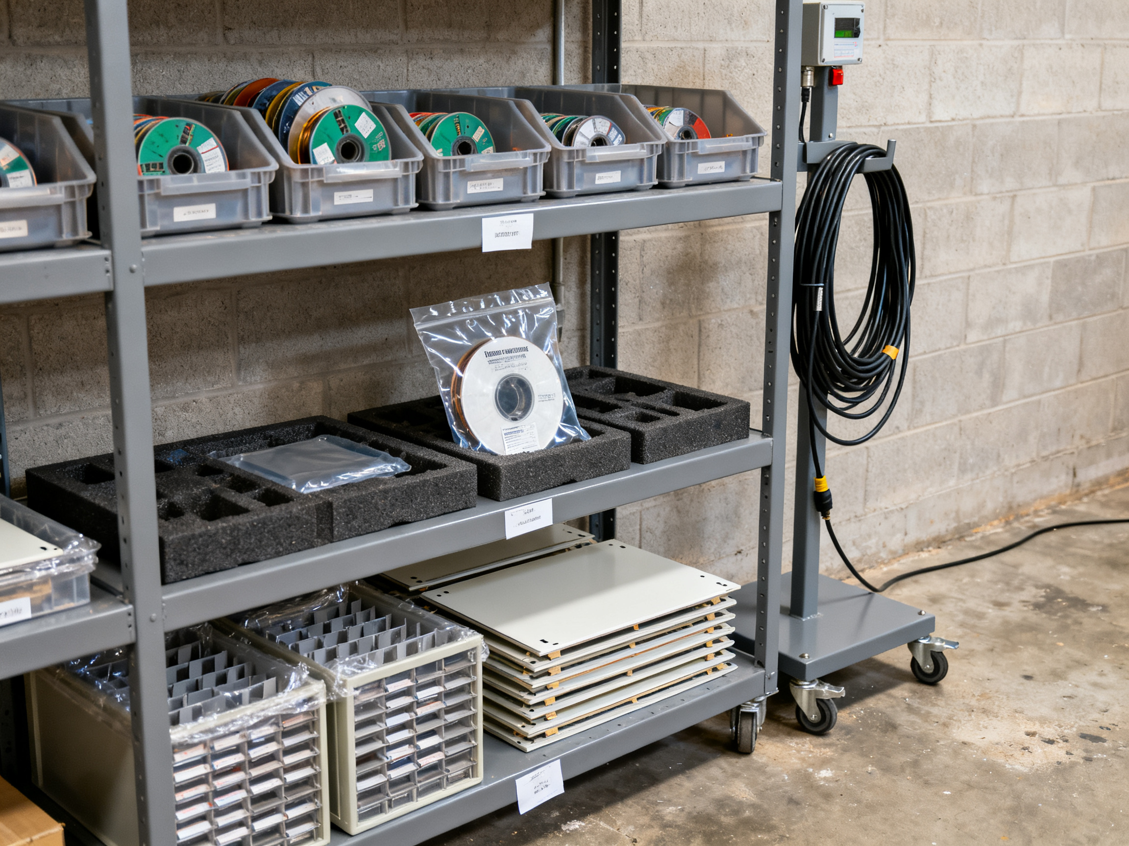
The fix starts with picking the right container for the product. A PCB storage box with sealed conductive foam protects bare panels from dust and humidity. A PCB storage rack with grounded shelves handles quantity. A PCB magazine keeps panels flat and at a repeatable pitch for machine loading. PCB handling trays with conductive or dissipative liners protect parts in transit. No single option wins on everything, so here is how they compare.
| Container type | Ideal use | ESD properties | Mechanical protection | Automation fit | Cleaning | Main limitation |
|—|—|—|—|—|—|—|
| PCB handling trays (conductive liner) | Moving populated assemblies and rework | Good if liner and tray are qualified | High, dividers prevent part contact | Medium | Easy, wipeable liner | Open to dust unless covered |
| PCB storage box (sealed, foam) | Bare panels, off-line storage | Good with sealed conductive foam | High, flat stack with separator | Low | Harder, foam traps debris | Not for magazine loading |
| PCB storage rack (grounded) | Bins of trays and reels by lot | Good when bonded to ground | Medium, depends on shelf lip | Low | Easy | Needs labelling discipline |
| PCB magazine | Machine loading and panel transfer | Frame must be bonded | Very high, panels stay flat | High | Harder, rails collect debris | Fixed pitch and panel size |
| Cart (bonded ESD-safe) | Line-side replenishment | Good with bonding point and shelves | Medium | Low | Easy | Needs parking and charging discipline |
| Moisture-barrier bag plus desiccant | Opened reels of MSL parts | Limited, bag protects in transit | None | n/a | Single use | Must track floor life after opening |
What good storage actually controls
- ESD. Shelves, carts, and magazine frames need a real bonding path. A metal frame under powder coat is not automatically grounded.
- Humidity and temperature. Keep bare boards in their original packaging until use, and log the climate where they sit. IPC-1601 covers printed board handling and storage guidance, and it is worth reading alongside your board supplier’s instructions, which can be stricter.
- Dust, sunlight, and stacking pressure. Sunlight fades solder mask and marking. Heavy stacks bow panels.
- Separation and labelling. One lot per bin, label facing outward, FIFO on the oldest opening date.
- Lot traceability. Barcode the location, not just the product.
Here is the part people skip. Different products need different storage. Bare PCBs need dust and moisture control. Opened reels of moisture-sensitive components need floor-life tracking under J-STD-033D handling rules and dry storage, not a warm shelf near the reflow oven. Solder-pasted boards have a short life before they dry out, so they belong in a short-term queue, not a rack. Finished assemblies need divider trays. Boards in rework need a physically separate hold location so they never mix with good product.
From Our Experience: The most common storage defect we see is a divider that was never qualified. A plastic rack divider with a sharp edge will cut a board edge, and the scratch only shows up at final inspection weeks later. Validate the rack liner on your worst panel, not your sample coupon.
flowchart TB
    subgraph LineSide[Line-side cabinet]
        A[Grounded cart]
        B[Trays by work order]
        A --> B
    end
    subgraph Store[Controlled storage]
        C[Sealed box: bare panels]
        D[Grounded rack: reels + trays]
        E[Dry cabinet: opened MSL reels]
    end
    subgraph Quarantine[Quarantine]
        F[Hold and rework bins]
    end
    LineSide --> Store
    Store --> Quarantine
If you are building out storage alongside a new SMT line, ask for the racks, carts, and magazine loading to be quoted with the equipment so the heights and interfaces match. S&M Co. Ltd. builds reflow ovens, wave soldering machines, and complete SMT lines, and the handling and storage pieces are specified together with the machines they feed, which removes a lot of guesswork from the install.
Need a storage layout for a specific mix? Send the board sizes, panel quantities, and monthly volume, and the author will reply with a recommended rack and tray setup.## 6. Building a Standard PCB Handling Procedure
Everything covered so far stays theoretical until somebody writes it down. A standard PCB handling procedure turns good practice into an auditable SOP that a new operator can follow on their second shift without asking a question.
The SOP framework
A workable PCB handling procedure covers nine stages. Each one needs a trigger, a product control, and a record:
- Receiving and quarantine. Material arrives, is logged, and stays in hold until identity is confirmed against the purchase order.
- Identification. Every board, panel, and reel is scanned and linked to work order, part number, revision, and lot.
- Inspection. Incoming condition is checked against IPC-A-600 and the supplier’s acceptance criteria, including moisture-barrier bag integrity and humidity indicator cards.
- Movement. Material moves only in approved trays, carts, or magazines, with ESD controls in force the entire time.
- Machine loading. Orientation, gap, rail width, and recipe are confirmed before the first board enters the machine.
- Unloading. Boards are received into the next station’s tray, never onto a bare bench surface.
- Temporary storage. Bare boards stay in supplier packaging; opened reels go to controlled storage with floor-life tracking under J-STD-033D.
- Rework. Suspect product moves to a physically separate hold location with a scan event and a recorded disposition.
- Final disposition. Conforming assemblies are packed, labelled, and released with a complete history.
The IPC standards catalogue supplies the acceptance criteria behind stages 1 through 9, but the SOP itself is what makes them enforceable on a night shift.
Who owns what
| Activity | Production | Quality | Maintenance | Warehouse |
|—|—|—|—|—|
| Receiving identity check | C | A | I | R |
| ESD program verification | I | A | C | I |
| Tray, magazine, and cart inspection | R | I | A | C |
| Line conveyor checks | C | I | A/R | I |
| Rework disposition and records | R | A | I | I |
| Storage conditions and floor life | C | A | I | R |
R means responsible, A means accountable, C means consulted, I means informed.
Shift-start checklist
- Wrist strap tested, worn, and clipped to a personnel grounding point
- Grounding points on carts, racks, and magazine frames confirmed
- Transfer points checked for debris, belt tracking, and sensor alignment
- Magazines inspected for bent rails, damaged pins, and broken bonds
- Trays and liners checked for cracks, sharp edges, and contamination
- Hold and reject bins emptied, labelled, and current
- Opened reels reviewed against floor life before they reach the feeder
Monthly audit scorecard
| Item | Target | Evidence |
|—|—|—|
| Shift checklists completed | 100% of shifts | Signed records |
| ESD verification on schedule | 100% | Test logs |
| Damaged boards found at final test | Under 0.5% | AOI and test data |
| Traceability records complete | 100% of lots | MES export |
| Magazine and tray damage findings closed | Within 5 days | Maintenance log |
If a line cannot show you these five numbers, the SOP is a document on a server, not a control on the floor.
Building this out alongside a new SMT installation makes more sense than after the fact. S&M Co. Ltd. specifies handling and storage components together with the reflow ovens and complete SMT lines they feed, so the interfaces are already matched. If you want a draft SOP built around your actual board mix and throughput, send the details and the author will reply with a next step.## 7. How to Choose the Best PCB Handling Tools and System
Picking handling equipment on price alone is how lines end up with conveyors that fight the machines they feed. A better approach starts with your products, not a catalog.
Frame the selection around board dimensions, weight, component clearance, fragility, throughput, product mix, ESD class, cleanroom needs, traceability requirements, and the floor space you actually have. Then check integration: adjustable rail width, supported communication protocol, upstream and downstream compatibility, recipe control, maintenance access, and room for the line to grow.
Vendor evaluation scorecard
| Criterion | Weight | Score (1-5) | Evidence required |
|—|—|—|—|
| Product fit (size, clearance, fragility) | 25% | | Trial run on your worst board |
| Line integration and protocol support | 20% | | Hermes or SMEMA statement |
| Defect reduction on your process | 15% | | Customer reference data |
| Total cost of ownership | 15% | | 5-year service and spares cost |
| Service, spares, training support | 15% | | Local response commitments |
| Validation and documentation support | 10% | | IQ/OQ paperwork quality |
Requirements checklist by team
- Production: cycle time, changeover time, manual intervention rate, jam recovery.
- Engineering: rail adjustability, gapping range, panel geometry limits, recipe storage.
- Quality: ESD qualification, traceability events, reject routing, contamination control.
- Maintenance: access, standard parts, cleaning tasks, preventive maintenance plan.
- IT and MES: protocol, event data, identifier format, network security and change control.
- Procurement: lead time, warranty terms, spares pricing, local service coverage, full quote scope.
Compare total cost of ownership, not purchase price. A cheaper conveyor with no spare rollers in the region and no validation support costs more in year two. Ask for the defect reduction it achieved on a line like yours, then verify it.
Planning an upgrade? Get conveyors, buffers, inspection, and storage quoted as one package. S&M Co. Ltd. specifies handling and storage components together with the reflow ovens and complete SMT lines they feed, so the interfaces match before the equipment reaches the floor.
Send the board sizes, product mix, and throughput numbers, and the author will reply with a recommended setup and the standards that apply.
Sources: IPC standards catalogue, IPC-HERMES-9852, IEC 61340-5-1:2024## Conclusion: Make PCB Handling a Controlled Part of Process Quality
Reliable PCB handling does not come from a single purchase. It comes from the combination of suitable equipment, qualified ESD-safe materials, disciplined transfer methods, controlled storage, working traceability, and operators who follow the same steps on every shift. Miss any one of those and the board arrives at the next operation in the wrong condition, no matter how fast the placement machine runs.
Five steps you can start on Monday:
- Map every board touchpoint. Write down where boards are touched, rested, stacked, waited on, and moved.
- Flag the high-risk transfers. The handoff points, manual moves, and rework paths where damage and mix-ups actually occur.
- Audit your storage materials. Check dividers, liners, racks, and magazine rails against your worst panel, not a sample coupon.
- Confirm protocol compatibility. Check whether each machine speaks Hermes or legacy SMEMA signals before commissioning, not after.
- Standardize the SOP. One written procedure, one set of steps, one record, every shift.
[Author perspective placeholder: insert the author’s evidence-based recommendation drawn from verified SMT or PCB production experience.]
Need help deciding where to start? Request a PCB handling assessment, a line-layout review, or an equipment consultation, and the details of your board mix, throughput, and pain points will come back with a recommended next step and the standard that applies.## Priority Research Focus
Before you change a single conveyor, tray, or rack, you need to know what actually governs your line. This appendix lays out the three research priorities for a PCB handling and storage project in 2026, in the order they should be worked, plus where to source each answer.
Priority 1: Standards and safety
Start with the primary standards bodies, not with a vendor brochure. As of November 2026, the layered baseline for handling PCBs and PCBA assemblies looks like this:
| Area | Governing document | What it settles |
|—|—|—|
| ESD program | IEC 61340-5-1:2024 and ANSI/ESD S20.20 | EPA boundaries, grounding and bonding, personnel grounding, verification |
| ESD packaging | IEC 61340-5-3 | How ESD-sensitive devices are packed, moved, and verified |
| Moisture classification | J-STD-020F | MSL 1 through 6, floor life, reflow exposure limits |
| Moisture handling | J-STD-033D | Dry pack, desiccant, humidity cards, bake and reseal rules |
| Board and assembly acceptability | IPC-A-600, IPC-A-610, J-STD-001, IPC-1601 | What counts as a good board, a good assembly, and how it must be stored |
| Rework | IPC-7711/7721 | Rework, modification, and repair process controls |
| Machinery safety | ISO 12100, IEC 60204-1, ISO 13849-1, IEC 62061 | Risk assessment, electrical equipment, safety-related controls |
| Line communication | IPC-HERMES-9852 and legacy IPC-SMEMA-9851 | Board transfer signals, board identifiers, product type |
Two points deserve emphasis. First, the 2024 edition of IEC 61340-5-1 replaced the 2016 edition and pulled in revised product qualification rules, controls for isolated conductors, expanded compliance verification, and a new summary table covering packaging requirements under IEC 61340-5-3. Second, a standard is only binding when it is adopted by contract, regulation, certification, or your own declared quality system. The words “ESD safe” on a product label prove nothing.
Hermes versus SMEMA is the decision that quietly affects every future upgrade. Hermes carries unique board identifiers across the line and names the first machine that noticed a board, which is exactly the data your traceability program needs. SMEMA still moves boards, but it says little about which board is which.
Pro Insight: Put the exact document number, revision letter, publication date, and contractual applicability into the production quality plan. “IPC compliant,” “ESD safe,” and “MSL controlled” are not precise enough to audit against. The current IPC standards catalogue and the IPC guidance document on handling and storage are the right starting points, but the purchased document is the only version that counts.
Priority 2: Technical evidence
Now collect data that shows where your line actually loses money. Pull defect, rework, downtime, contamination, moisture, and ESD records from the last twelve months and break them down by station and by product family. Specific questions worth answering:
- Which defect codes trace back to handling rather than to printing or placement?
- How many jam events per week, and what is the average recovery time?
- What is the current scrap rate on fine-pitch BGA and QFN work?
- What share of boards sit in line-side storage longer than one shift?
- Are there customer returns tied to corrosion, contamination, or delayed solderability?
Look for case studies in high-volume consumer, semiconductor, automotive, military, and aerospace work, since those sectors publish the most detail about moisture failures, ESD incidents, and rework loops. Where a paper or conference study is available, prefer peer-reviewed work over vendor marketing. Where it is not, a documented plant case study with named failure modes beats a general claim.
Watch the timing. As of November 2026, no verifiable 2025 or 2026 revision change log exists for J-STD-020F, J-STD-033D, the IPC acceptability documents, or the core machinery-safety standards. What changed is limited to the IEC ESD edition noted above. Claims of a “new 2026 standard” in these areas should be treated with suspicion until a publication date appears on the publisher’s own page.
Priority 3: Buyer utility
Finally, get the selection criteria tied to something a plant manager or procurement lead can sign off on. Validate specifications with engineers and operators, not only with sales. The items that matter most:
- Equipment specifications tested against your worst board, not a sample coupon
- Tool material properties, including liner conductivity, liner life, and chemical compatibility with solder mask
- Real ROI inputs: changeover time, manual intervention rate, jam recovery, first-pass yield
- Integration tests: rail width range, gapping range, protocol support, footprint
- Maintenance requirements: standard parts, cleaning tasks, preventive maintenance intervals, local service coverage
- Vendor-selection criteria weighted toward total cost of ownership over five years
Ask for defect reduction achieved on a line with a mix similar to yours, then verify it with a reference call. A cheaper conveyor with no spare rollers in the region and no validation paperwork costs more in year two.
S&M Co. Ltd. builds lead-free reflow ovens, wave soldering machines, and complete SMT lines for consumer electronics, semiconductor, and military customers, and specifies handling and storage components together with the machines they feed. That kind of bundled specification answers a lot of the Priority 3 questions before a purchase order is written.
Source hierarchy for this research
- Standards organizations and government material first. IEC, IPC, JEDEC, ISO, OSHA, BIS. These set requirements.
- Peer-reviewed studies and recognized associations next. AIME, IEEE, SMTA, and peer-reviewed journal articles supply evidence and failure modes.
- Qualified manufacturers next. Use them for specifications, tolerances, and material data, then confirm against the standards.
- Expert interviews and verified case studies last. Useful for context and tradeoffs, never as a substitute for a standard.
Working the priorities in order keeps you out of the most common mistake in handling projects: buying equipment first and discovering the standard requirements afterward.## Appendix: Keyword Placement Map
Here is the placement plan for this guide. It exists so every target phrase lands in the section where a reader who searched for it actually expects an answer. It also keeps the writing honest, because a keyword that appears in a header and nowhere in the body is a promise the article does not keep.
| Keyword | Search intent | Placement | Notes |
|—|—|—|—|
| pcb handling | Broad, informational | Title, introduction, Section 1 header and body, Section 3, conclusion | Anchor term. Used where the topic is genuinely the whole system, not a subtopic |
| what is pcb handling | Definition | Section 1 opening | Answered in the first two sentences, then expanded |
| how pcb handling systems work | Mechanism | Section 1, station chain and signal handshakes | Paired with the loader, buffer, turn unit, unloader diagram |
| how pcb handling is done | Practice | Sections 3 and 4 | Described through sequence, not definition |
| pcb board handling | Physical risk | Section 2 risk matrix | Ties hazards to stage of the flow |
| pcb handling guidelines | Rules and practice | Section 4 checklist, Section 6 SOP | Appears where operators act |
| pcb handling procedure | Procedure | Section 4 header and Section 6 header and body | The eight-step manual procedure and the nine-stage SOP |
| pcb handling and storage | Combined | Section 5 header and opening | Bridges conveyance with the storage decision |
| pcb handling trays | Commercial, product-led | Section 4 transfer tool table, Section 5 container comparison | Used alongside conductive liner and divider language |
| pcb storage box | Product-led | Section 5 container comparison | Paired with sealed conductive foam for bare panels |
| pcb storage rack | Product-led | Section 5 container comparison | Paired with grounded shelves and lot separation |
| pcb magazine | Product-led | Section 5 container comparison, Section 4 tool table | Ties to machine loading and repeatable pitch |
| best pcb handling material | Comparison | Section 5, container table | Answered by qualification criteria rather than brand names |
| best pcb handling tools | Comparison | Section 7 header and scorecard | Answered with weighted criteria and trial-run evidence |
| handling pcbs | Casual, broad | Introduction and Section 6 | Used sparingly, mostly in plain sentences |
Why the placement follows the flow of the line
Search intent follows a path. Somebody searching for what PCB handling is wants a definition. Somebody searching for how PCB handling systems work wants the mechanics of a chain of stations. Somebody searching for PCB handling and storage wants to know where product waits and what protects it. Somebody searching for best PCB handling tools is close to a purchase decision and wants criteria, not a listicle of top picks.
So the phrase “what is PCB handling” does the work in Section 1, and “best pcb handling tools” does the work in Section 7. Putting either one in the wrong section breaks the match between the question and the answer, which is the whole point of writing for search at all.
Supporting semantic terms
These phrases carry meaning without repeating the target strings. They also happen to be the words people use on the floor, so they make the guide easier to scan:
- ESD-safe conveyor and grounded transfer conveyor
- SMT loader and unloader, magazine loader
- PCB buffer and accumulation buffer
- Board transfer and transfer height
- Work-in-process storage and line-side replenishment
- Line balancing and takt time
- Traceability events and lot control
- Conductive tray, dissipative liner, anti-static tray
- Moisture control, floor life, bake procedure
- First-pass yield, jam recovery, mean time to recover
Phrasing rules for anyone editing this guide
First, keep the exact target phrase in the body of the section, not only in the heading. Second, use the header wording that matches the question being answered rather than a clever variant. Third, do not stack variants in the same paragraph. If “pcb handling trays” and “best pcb handling material” appear together, the section reads like a catalog, and the reader stops trusting the rest.
Fourth, use the plain form of the phrase early in a section and the qualified form later. For example, “pcb storage rack” in the opening sentence of Section 5, then “grounded storage rack” once the general idea is established. Fifth, keep commercial intent honest. A phrase like best PCB handling tools has to be answered with weighted criteria, trial evidence, and total cost of ownership, because that is what the reader is actually trying to work out.
And one last rule. If a standard changes, the keyword plan does not. The document numbers and editions referenced throughout this guide, including the current IPC handling and storage guidance and the IPC standards catalogue, need to be rechecked whenever the source is republished. The keywords can stay put; the claims behind them cannot.
Want the article structure mapped to your own line documentation? Send your current SOP outline and the author will reply with a suggested section order and where the standards fit.