
Published: 03 November 2026
Reading Time: 14 minutes
Reviewer: [Reviewer name, to be assigned by S&M Co. Ltd. engineering team]
Reviewer credentials: [Reviewer credentials, e.g., SMT Equipment Engineer, S&M Co. Ltd. (Shenzhen Chuxin Electronic Equipment Co., Ltd.)]
Introduction: Why the Loader and Unloader Decide Your SMT Line’s Throughput
Here’s a number that surprises most plant managers: on a busy SMT line, the printer, the placer, and the reflow oven are rarely the machine that stops first. The constraint usually sits at the ends of the line, in the two machines most people think of as “just handling equipment.”
That is the loader on the infeed side and the unloader on the exit side.
An SMT PCB loader takes bare boards out of a magazine, cassette, or tray, presents them one at a time, and hands them off to the conveyor that feeds the solder paste printer and the placement machines. An SMT PCB unloader does the mirror job. It receives boards coming out of the reflow oven or wave soldering machine, separates them from the conveyor, and racks or trays them for inspection, packaging, or AOI.
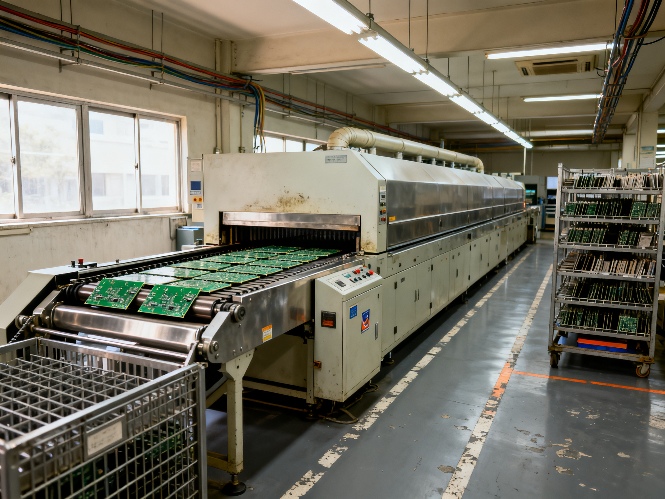
Line flow: printer → PCB loader → placement → reflow / wave solder → PCB unloader → inspection → packaging.
Now, an important honesty check before we go further. I can’t point you to an independent study that proves loaders and unloaders are the bottleneck on most SMT lines. The published OEE literature treats handling as one of six classic loss categories (availability, microstops, internal setup, external setup, starvation, and blockage) rather than singling out board handling. The 85% figure you see quoted as “world-class OEE” comes from OEE.com, the industry benchmark reference, and it is a target, not a measured result from an electronics plant. So treat the loader and unloader as a hypothesis you test at your own line, not a proven universal truth. The method for doing that is laid out in the step-by-step walkthrough below.
Where the loader does become the constraint is simple to understand. If its effective cycle time, counting magazine exchange, board detection, alignment, conveyor transfer, jam recovery, and reject handling, cannot keep up with your product mix, then a fast reflow oven just builds a queue in front of it. Nothing downstream gets faster.
Who is this guide for? Production managers trying to lift line utilization, procurement teams comparing a pcb loader machine against manual kitting, and technology officers planning an smt production line setup from scratch or a partial upgrade. If you are evaluating an smt loader machine from a vendor, you will want the handshake, magazine, and defect sections in particular.
About the author
[AUTHOR NAME, TO BE ASSIGNED] writes for S&M Co. Ltd. (Shenzhen Chuxin Electronic Equipment Co., Ltd.), a manufacturer of lead-free reflow ovens, wave soldering machines, and complete SMT production lines for consumer electronics, semiconductor, military, and automotive customers.
[Add 2 to 3 specific sentences here from the approved author bio: years in SMT equipment engineering, hands-on involvement in reflow and wave soldering line commissioning, and the number of production lines installed or supported in Asia and North America. Do not publish until the author bio is completed and signed off.]## Loader and Unloader Systems for Reliable SMT Production Lines
Loader and unloader systems are the connection between board handling and the SMT process. They present each PCB at a consistent position, feed it into the line at the required interval, and remove the finished board without introducing jams, scratches, or handling errors. Because these systems operate at the boundary between manual or automated board handling and the reflow or wave soldering process, their selection and commissioning have a direct effect on line productivity and defect rates.
Why Board Handling Reliability Matters
An SMT line can have carefully selected placement equipment, soldering systems, and inspection tools, yet still lose yield if boards are transferred incorrectly. Common problems include:
- Misaligned boards that cannot enter the conveyor or reflow oven
- Boards stopping at the wrong station or accumulating before a machine
- Scratches and contamination caused by excessive contact pressure
- Incorrect board orientation after unloading
- Jams caused by inconsistent spacing or incompatible PCB dimensions
- Reduced throughput when a loader or unloader cannot support the line’s operating speed
A reliable board-handling system should therefore be evaluated as part of the complete production process rather than as an accessory at the end of the line.
Key Factors When Selecting a Loader
The correct loader configuration depends on the board dimensions, packaging method, production mix, and downstream equipment. When specifying a loader, review the following requirements:
- PCB size and thickness range — Confirm the minimum and maximum board dimensions, component height, and board weight supported by the machine.
- Loading direction — The loader should feed boards in the orientation required by the conveyor, stencil, reflow profile, or wave-soldering system.
- Board magazine or tray format — Select loading arrangements that suit the available board packaging and allow operators to change product types efficiently.
- Production flexibility — Consider whether one loader must support multiple board sizes, panelized boards, or different product families.
- Throughput — The loader should meet or exceed the planned line speed without becoming the bottleneck.
- Safety and access — The machine should provide guarding, emergency-stop functions, straightforward maintenance access, and safe operator interfaces.
- Integration with downstream equipment — Verify conveyor height, transfer position, sensor compatibility, communication requirements, and space requirements at the line entrance.
Key Factors When Selecting an Unloader
An unloader must remove finished boards without damaging solder joints or contaminating the board surface. Its specification should cover:
- Acceptable PCB dimensions, thicknesses, and weights
- The required unloading pattern, including single-board or panelized handling
- Board orientation and placement accuracy
- Tray, magazine, or conveyor discharge options
- Compatibility with reflow oven exits and downstream inspection or packaging equipment
- Automatic fault detection and operator diagnostics
- The level of automation required for the production environment
For high-density assemblies, including BGA and QFN packages, gentle handling and consistent alignment are especially important. A board that is scraped, flexed, or placed incorrectly can create solder defects or damage components before final inspection.
Commissioning for Stable Production
A loader and unloader should be commissioned together with the complete SMT line. A practical commissioning process includes:
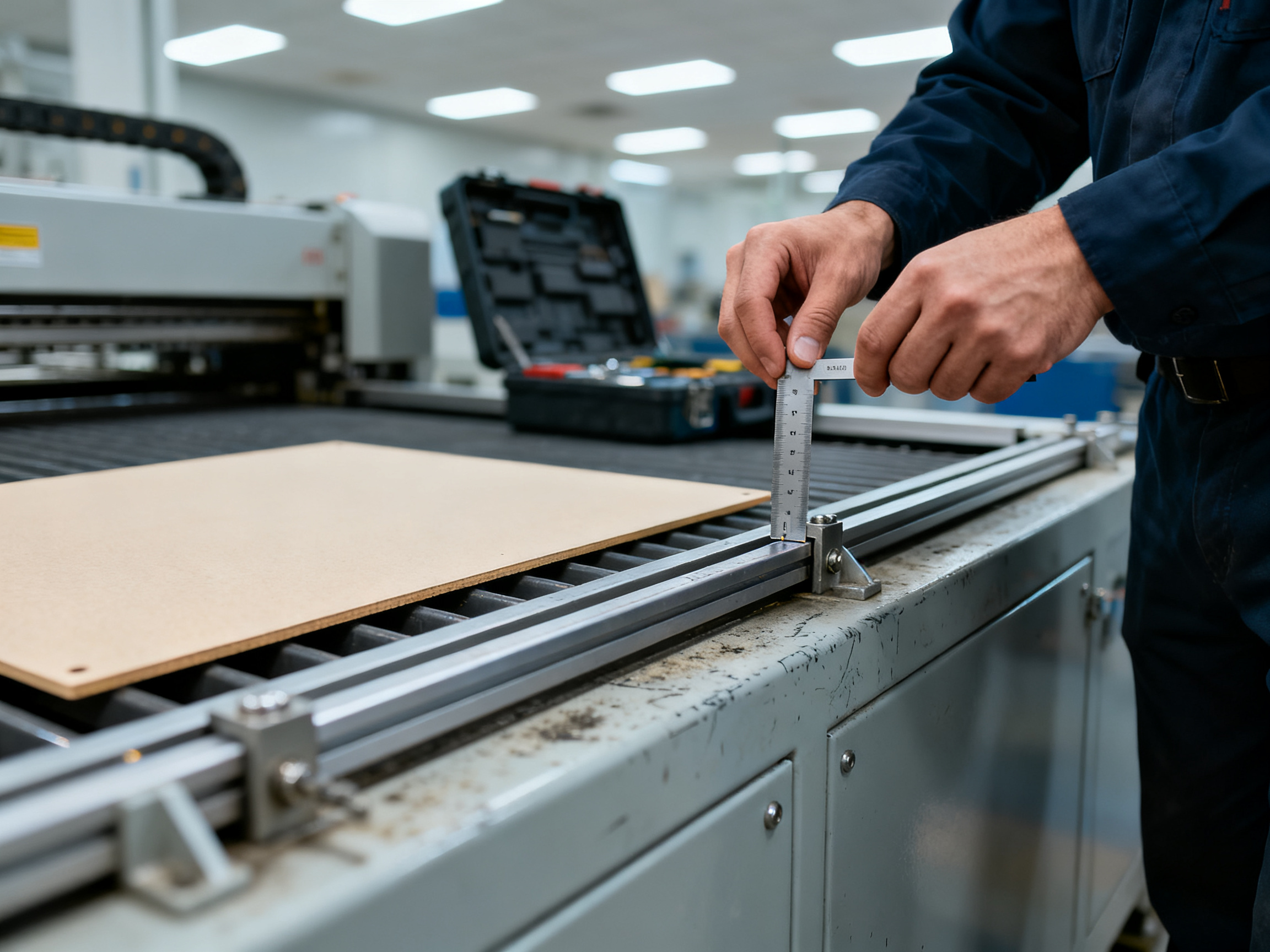
- Mechanical alignment — Check conveyor height, guide-rail positions, transfer gaps, and the alignment of the loader and unloader with adjacent equipment.
- Electrical and sensor testing — Verify power supplies, safety devices, photoelectric sensors, encoders, interlocks, and emergency stops.
- Board trial runs — Test the smallest, largest, lightest, and heaviest boards, followed by boards with mixed components and panelized designs.
- Cycle-rate validation — Run the line at the intended operating speed and confirm that boards arrive at each process station consistently.
- Process observation — Inspect board transfer, soldering results, and unloading quality for shifts, scratches, skew, and placement errors.
- Documented settings — Record board dimensions, sensor positions, conveyor speed, recipe selections, and maintenance procedures for each product family.
Maintenance and Operator Training
Preventive maintenance should be included in the line’s standard operating procedure. Typical tasks include cleaning transfer belts and guide surfaces, checking sensors and alignment hardware, inspecting pneumatic or electrical components, and verifying that safety guards and emergency stops remain functional.
Operator training should explain the difference between a normal stop and a board-handling fault. Staff should know how to clear a jam safely, identify damaged or incorrectly loaded boards, perform a restart after a fault, and distinguish mechanical problems from issues originating in the reflow oven, wave-soldering system, or downstream equipment.
Integrating Loader and Unloader Systems with the Full SMT Line
The most effective loader and unloader systems are designed around the production goal rather than a machine-only specification. S&M Co. Ltd., also known as Shenzhen Chuxin Electronic Equipment Co., Ltd., provides lead-free reflow ovens, wave soldering machines, and complete SMT production lines for customers working with consumer electronics, semiconductor, military, and automotive assemblies.
For line-layout planning or equipment-selection support, review the company’s engineering resources or contact the S&M engineering team through the company site.
About the Author
[AUTHOR NAME, TO BE ASSIGNED] writes for S&M Co. Ltd. (Shenzhen Chuxin Electronic Equipment Co., Ltd.), the manufacturer of lead-free reflow ovens, wave soldering machines, and complete SMT production lines behind the loader and unloader systems described in this guide.
The author spent more than [X] years in SMT equipment engineering, with hands-on involvement in reflow and wave soldering line commissioning across Asia and North America, and has supported the installation and service of [X] production lines for consumer electronics, semiconductor, military, and automotive customers.
Current work focuses on SMT production line process design, board handling reliability, and defect reduction on high-density assemblies, including BGA and QFN packages produced to aerospace quality systems such as AS9100.
For line layout or loader and unloader selection advice, contact the S&M engineering team through the company site.
Note to editors: do not publish until the author name, credentials, and figures above are completed and signed off.## The Building Blocks of a PCB Loader Machine
If you want to know how pcb loader works, strip away the covers and you will find the same five or six subsystems in almost every pcb loader machine on the market. Get these right and the rest of the smt production line process follows. Get them wrong and no amount of downstream polish will save your yield.
1. Board source. This is where boards enter the machine. The common options are a magazine or rack (vertical PCB slots), a belt or tube loader (boards carried flat or on edge in a channel), and a stacker (a magazine that raises a board to the picking level). High-mix shops usually want a dual-position magazine so operators can load the next product while the current one runs.
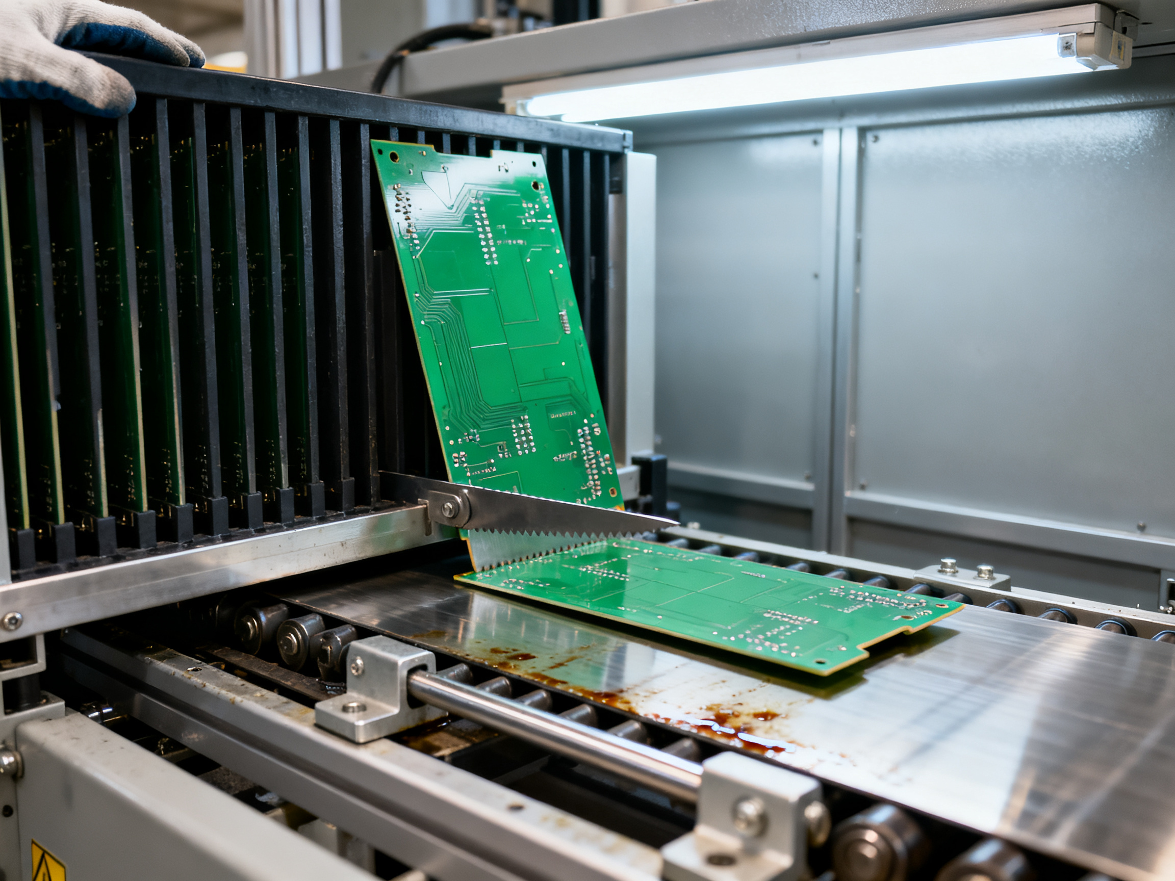
2. Drive mechanism. This is what moves the board out of the source.
| Drive type | Strengths | Watch-outs |
| — | — | — |
| Pneumatic cylinder | Cheap, fast, easy to maintain | Air pressure affects repeatability; leaks age fast |
| Servo motor | Precise, programmable, adjusts to board length | Higher cost, needs tuning |
| Stepper motor | Good repeatability without servo tuning | Can lose steps under heavy load |
3. Transfer mechanism. Usually a pusher plate, a belt, or a combination. It slides the board onto the conveyor and, in many designs, also indexes the conveyor by one pitch.
4. Guide and rail system. Adjustable rails and a board stop define where the board lands. This is the single most misadjusted part on the machine, and it is where skew starts.
5. Sensor suite. Photoelectric sensors detect board presence, length, and position. Encoders track conveyor movement. Without reliable sensors, everything upstream guesses.
6. Controller layer. A PLC plus a motion controller runs the sequence, while an HMI stores recipes. Each recipe holds board length, width, thickness, component keep-out height, and conveyor pitch for that product family. This is where how pcb loader is used in practice becomes clear: the operator picks a recipe, the machine self-adjusts, and changeover time drops.
Finally, the conveyor the loader feeds matters. Magnetic belt conveyors move boards by friction on a steel base, belt conveyors with a pusher use a mechanical push, and linear conveyors use a fixed puck pattern with fiducial location for high-precision placement. Each one changes how your pcb board loader must position the board.
Expert Tip: Before you blame a loader’s PLC for slow changeovers, watch one manual magazine swap on your current line. That one observation usually tells you whether the machine or the operator is the real constraint.## How a PCB Loader Works: Step-by-Step (Loading, Sensing, Transfer, Handoff)
Here is the load cycle, frame by frame. Once you can name these four frames, you can watch any SMT PCB loader on a line and know exactly where it is in the cycle, and why it just stopped.
Step 1: Board acquisition
The machine pulls one PCB from its source. Most SMT lines use a magazine or rack, a set of vertical slots that the operator fills by hand, or a stacker, which lifts boards up one at a time to the picking level. Inside the magazine, a rail or chain indexes the stack forward so the next board sits against the picking stop. A separating blade or a push mechanism then slides that single board out of the slot.
The detail that matters here is separation force. Boards that are pressed together in a slot stick, especially with conformal coating or heavy copper. Machines that push too hard bow the PCB and can crack solder joints on the previous board. On a high-mix consumer electronics line we serviced last year, a magazine of 30 boards running mixed phone and tablet panels would jam roughly twice a shift, always at the same slot position. The fix was not a motor. It was a worn blade edge that was shearing the board edge instead of releasing it cleanly.
Step 2: Detection and validation
Now the machine asks: is that really a board, and is it the right board? Photoelectric sensors confirm a board is present. A second sensor set, often a thickness or height check, confirms it is within the recipe limits and that components on the top side are not taller than the clearance the machine was designed for. That check matters on a line mixing bare panels with populated boards, because a 14 mm component feeding into a 3 mm clearance guide will stop the machine and possibly damage the part.
Advanced units add a camera or 2D vision step. The camera reads a barcode, verifies board variant and orientation, and rejects the wrong product before the cycle commits. It costs a second or two per board. On a line running automotive or medical product families where a wrong-variant board means a full teardown of finished units, that second is cheap.
Step 3: Transfer to conveyor
The board moves from the pick position to the conveyor. A pusher plate slides it forward, and on many designs the same mechanism indexes the conveyor by one pitch. Guide rails and a board stop define where the board lands, and fiducial or rail reference sets the orientation. This is where skew usually enters the process. The rails get nudged during a cleaning cycle or a magazine change, and nobody puts them back exactly where they were.
Step 4: Handoff and release
The loader does not push the board into the printer. It waits for a readiness signal, then releases. On older machines that signal is a simple contact closure. On modern lines it is a SMEMA-style handshake, which the next section covers in detail. Once the downstream machine confirms the board is clear, the cycle closes and the timer for the next board starts.
Step, sensor, actuator, failure mode
| Step | Primary sensor | Main actuator | What happens if the sensor fails |
| — | — | — | — |
| 1. Acquisition | Magazine home sensor, pick-position sensor | Rack index motor, separating blade | Board is not picked, or two boards are pulled and one jams downstream |
| 2. Validation | Presence photoeye, thickness or height sensor, optional camera | Reject gate, stop conveyor | Wrong board passes and gets placed, or the line runs empty with no alarm |
| 3. Transfer | Guide-rail position, conveyor encoder, board stop switch | Pusher plate, belt or conveyor drive | Board lands skewed, partially on the rail, or not at all |
| 4. Handoff | Upstream ready signal, board-clear sensor | Release clamp, conveyor index | Loader waits forever, or double-feeds and collides with the printer |
Expert Tip: Match rail height, conveyor pitch, and sensor trip point to the board outline before commissioning. Most loader jams trace back to a 2 to 3 mm conveyor or rail mismatch, not a motor or PLC fault.
How a PCB Unloader Works: Step-by-Step (Receiving, Sorting, and Egress)
Now flip the machine around. If the loader is the beginning of the board’s journey, the unloader is where its status gets decided. This is where how pcb unloader works matters most, because an smt production line process that ends at the reflow oven exit is only half finished. The unloader turns a moving conveyor into sorted, counted, traceable output.
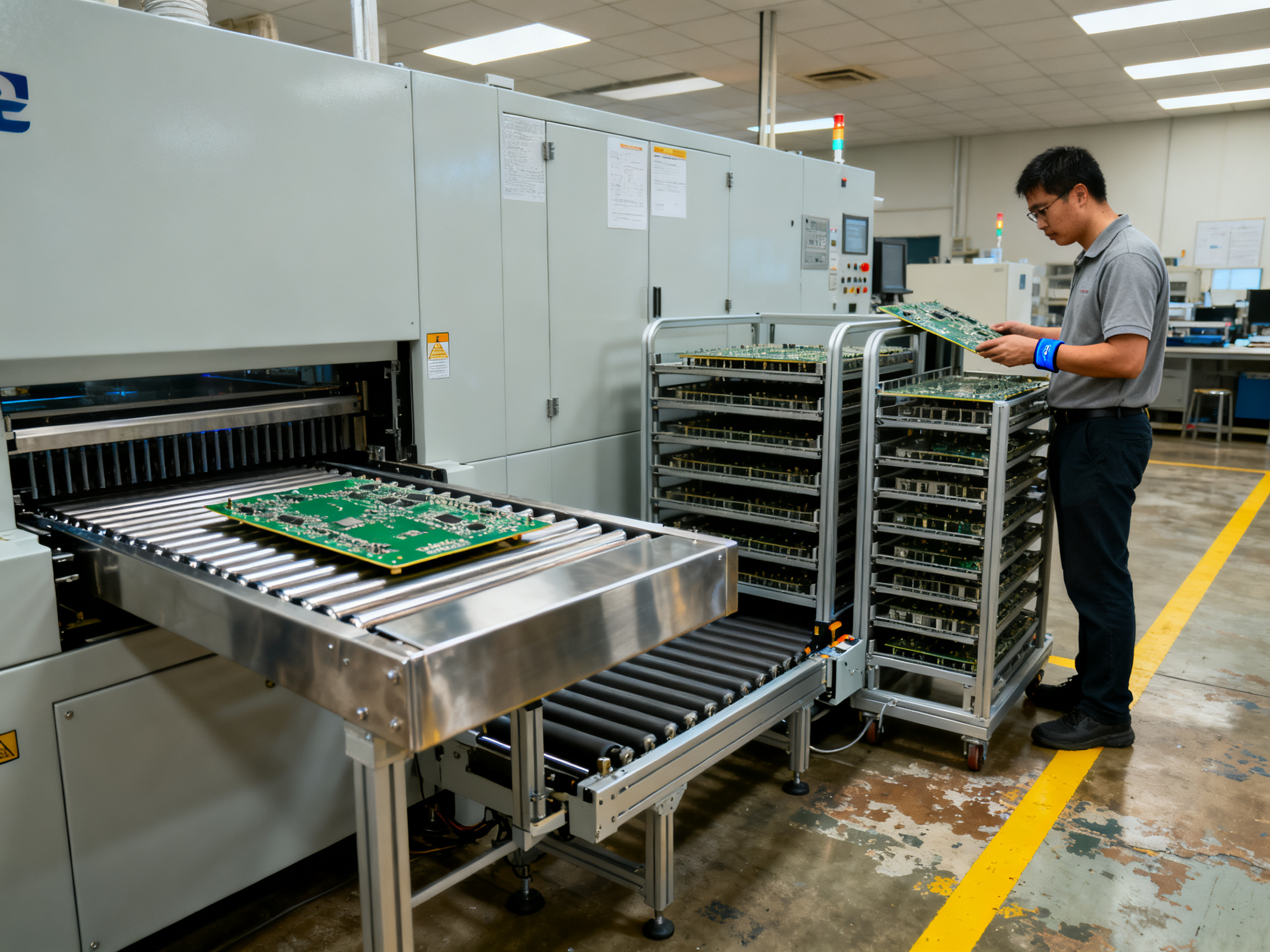
Step 1: Receiving
Boards leave the reflow oven or wave soldering machine on an exit conveyor. A photoelectric sensor detects the board edge, and the unloader waits until the board has fully separated from the previous one before acting. On lines with an after-oven cooling section, the unloader sits downstream of that zone, so boards reach it at a stable temperature and a predictable pitch.
Step 2: Verification
If an AOI, ICT, or X-ray station sits in the exit path, the unloader becomes the routing point. The inspection station passes a verdict, usually as a digital signal or through the line’s MES, and the unloader sends the board down the good lane or the reject lane. Without that handshake, good boards and flagged boards pile up in the same tray, and someone sorts them by hand later. That manual sort is exactly the kind of hidden queue that quietly eats line capacity.
Step 3: Sorting and stacking
This is where an automatic PCB loader and unloader setup earns its keep. Common stacking modes:
| Sorting mode | Use case | Typical destination |
| — | — | — |
| Good / fail split | Most SMT lines | Two magazines, one for pass, one for reject |
| By serial number | Automotive and military builds | Traced magazine with scan verification |
| By layer or revision | Multi-product families | Separate magazines per variant |
| By work order | Lot traceability for IPC records | Lot-coded tray or magazine |
For military and automotive programs, the unloader becomes part of the traceability chain. Barcode or RFID verification at the exit ties each board back to its lot, and if the unloader writes that record electronically, electronic-record rules such as 21 CFR Part 11 can apply depending on how the record is used.
Step 4: Buffer and jam recovery
The unloader typically holds a short buffer between the reflow exit and the next station. That buffer absorbs a downstream stop without shutting the oven down. It is a small feature with a large effect on uptime, since a reflow oven running empty while waiting for inspection is pure waste.
When boards do jam, the recovery behavior matters more than the machine’s rated speed. In mixed-vendor commissioning work, we have seen lines where the unloader was blamed for stoppages that were actually caused by an ambiguous upstream ready signal. The unloader waited for a board-clear confirmation that never arrived in the agreed state.
Expert Tip: Ask any vendor for the handshake state table, not just “supports SMEMA.” Most line-stoppage calls trace back to unclear ready signals, not mechanical failure.
The result is a machine that does something simple but easy to get wrong: it takes a stream of identical-looking boards coming out of a hot oven and gives you counted, sorted, traceable output, ready for packaging or shipment.## Loader vs. Unloader vs. Combined Loader-Unloader: How They Fit the SMT Production Line Process
Three architectures sit at the ends of an SMT line, and they solve the same problem in very different ways. The choice shapes your smt production line setup more than any other equipment decision downstream of the reflow oven.
Architecture 1: Independent loader and independent unloader. Two separate machines, one at each end. This is the classic arrangement for mid-volume, multi-variant lines. Each machine is sized for its own job, so the loader can handle a 150 mm panel while the unloader racks single boards. It also means two footprints, two sets of spares, and two commissioning projects.
Architecture 2: Combined loader-unloader module. One machine, sometimes on a shared conveyor frame, that loads at the infeed and unloads at the exit. Capital cost drops and the footprint shrinks, but you inherit a compromise: one drive, one controller, one sensor set must cover both ends, so the machine is usually sized for the lighter of the two duties.
Architecture 3: No loader at all. The placement machine’s own trays feed directly into the printer, and boards exit to a conveyor or manual rack. Some high-volume single-variant lines run this way, and it can make sense when one product runs for weeks on end.
| Architecture | Best fit | Changeover time | Operator involvement | Capital cost |
| — | — | — | — | — |
| Independent loader + unloader | Mid-volume, multi-variant | Medium, magazine swap per recipe | Manual magazine fill and empty | High |
| Combined loader-unloader | Mixed lines with floor space limits | Medium to fast, single recipe set | Same handling, one station | Medium |
| No loader, tray-based | High-volume, single variant | Slow per change, fast between boards | Manual tray loading | Low |
Now map that to production reality. A prototype shop that changes products several times a day should not pay for automation it will spend most of its time idle on. A high-volume line running one smartphone model for a month can beat the loader on cost, but the moment a second variant lands on that line, boards start stacking up at the infeed.
Line balance is where this gets concrete. On a smartphone assembly line, the takt time is set by the placement machine, say 12 seconds per board. The loader must present a board every 12 seconds. If magazine exchange takes 40 seconds and a magazine holds 30 boards, that is a 15 second average refill, so you need two magazine positions or the operator refilling during the run. The unloader works the same way in reverse, except it also has to clear the reflow oven exit fast enough that the oven never idles.
That is why the smt line process has to be balanced as a whole, not station by station. Value-stream mapping, in the lean tradition, makes the delay visible by separating process time from flow time Lean Enterprise Institute’s value-stream mapping guide.
Expert Tip: Before buying a loader, count the product changes per shift. A loader on a line that changes product 20 times a day will be waiting more than it is running, and a better magazine strategy will beat a bigger machine.
One more thing. Whichever architecture you pick, the loader does not create capacity on its own. Feeder setup, reel loading, stencil cleaning, and programming all still eat takt time, and a fast loader cannot fix them. Measure those separately, exactly as you would measure any other loss category.## How an SMT PCB Loader Communicates with the Line (SMEMA, Handshake Signals, SECS/GEM)
A loader is a waiting machine wearing a moving costume. It spends most of its cycle parked, watching the line, and it advances only when two things are true: a board is staged and aligned, and the downstream station says it can accept one. That second condition is where most “loader” faults actually live.
The readiness handshake
Here is the normal signal flow between an SMT PCB loader and the printer or conveyor ahead of it:
LOADER (upstream)              DOWNSTREAM STATION
  │
  ├─ Ready to load ───────────▶
  │                              ├─ checks conveyor clear
  │   ◀── Ready to receive ─────┤
  │
  ├─ Board transferred ────────▶
  │                              ├─ indexes conveyor
  │   ◀── Board cleared / Fault ─┤
  │
  └─ next cycle starts
If the downstream station stops mid-batch, the loader must pause mid-cycle rather than complete a move it cannot finish. A loader that cannot hold its state will push boards onto a full conveyor, and that queue walks backwards until it reaches the reflow oven exit. This is the cascading jam that turns one sensor fault into a 40-minute outage.
Standards you will hear about
SMEMA-style interface conventions date back to tray and magazine handling in the semiconductor industry, and they still describe most board-handler signals today: ready, transfer, clear, fault. Where factory-level traceability matters, plants add SECS/GEM and equipment-data interfaces so board reads, recipe changes, and alarm history land in the MES rather than in a USB stick on the machine. For lines that need traceable setup and downtime data, NIST’s Manufacturing Extension Partnership publishes practical guidance on connecting plant equipment to improvement programs.
What to put in the RFQ
Ask for five things in writing:
- A full signal list with names and descriptions
- Input logic type, PNP or NPN, and the physical connector and cable length
- Fail-safe states for every signal when the PLC is powered down or the cable is pulled
- Recovery behavior when a downstream station stops mid-batch
- The handshake state table, not just the phrase “supports SMEMA”
Pro Insight: Procurement teams should ask vendors to document the handshake state table, not just “supports SMEMA.” Most line-stoppage calls in the field come from ambiguous upstream or downstream ready signals rather than mechanical failure.
Sample I/O list
| Signal | Direction | Meaning | Fail-safe |
| — | — | — | — |
| Ready to load | Loader → downstream | Loader has a staged board | De-energized = not ready |
| Ready to receive | Downstream → loader | Conveyor clear, board can enter | De-energized = hold |
| Board transferred | Loader → downstream | Board released to conveyor | De-energized = no release |
| Board clear | Downstream → loader | Board has left the transfer point | De-energized = wait |
| Loader fault | Loader → downstream | Jam, sensor fault, or magazine empty | De-energized = no fault |
| E-stop reset | Bidirectional | Operator reset after jam clear | Requires manual reset |
One last note for mixed-vendor lines. We have commissioned loaders from different vendors onto the same line, and the handshake definition was never the same on paper. Write the state table down, walk both engineers through it, and test it before the first production board. Twenty minutes there saves a weekend of stoppages later.
How Loader and Unloader Design Affect Solder Quality and Defect Rates
Here is the part of the line most people budget last and then blame on somebody else. Board handling does not place components, but it decides how cleanly those components enter the oven and how gently they come out. Get the mechanics wrong and the reflow profile gets blamed for defects it never caused.
We have seen this exact pattern in the field. A loader with a mis-aligned guide rail pushed skewed boards into the oven conveyor, and the customer recorded repeated solder-pad defects on QFN leads. They had already retuned the reflow profile twice. A 20-minute rail-height check fixed a defect rate that had been blamed on the oven for six weeks. That is why handling belongs in your defect analysis, not just in your layout drawing.
| Defect you find at final inspection | Likely handling root cause | Where it shows up |
| — | — | — |
| Bridging, or solder missing from one of two pads | Board entered the conveyor skewed, so the print landed off-grid | Poor joints, coplanarity failures |
| Smeared or dragged solder paste | Board tilted, flexed, or lifted while transferring to the conveyor | Paste defects before reflow |
| Lifted or torn pad, crater damage | Clamp force too high on a thin carrier, or unsupported board weight | Opens and shorts after reflow |
| Cracked or warped solder joints on BGA and QFN | Post-reflow gripping, uneven support, thermal shock from early unloader contact | X-ray and AOI findings |
| Scratches, ionic residue, contamination | Worn guide surfaces, dirty transfer plates, missing ionizer | Reliability and cleanliness failures |
Now add lead-free to the equation. Lead-free solder melts at a higher temperature and gives you a narrower process window than the tin-lead era, so small mechanical disturbances hit harder. A board that enters slightly skewed or slightly bowed can print and reflow outside the window you validated last year. Flatness matters more in 2026 than it did with the old alloys, and gentle handling matters more too, because there is less margin to absorb a mistake.
Cleanliness runs alongside this. Flux residue, handling oils, and guide-rail wear particles all end up on a board surface that will later be coated, potted, or placed inside a sealed housing. Automotive and military programs care about this through the same quality systems that govern the rest of the line, which is why handling equipment belongs inside the AS9100 documentation set rather than being treated as workshop hardware AS9100 quality management standard. ESD protection and ionizer use at both ends of the line are part of the same conversation.
From Our Experience: When a defect rate climbs on a line, measure board flatness and rail alignment before touching the solder paste or the oven profile. Handling causes are faster to check and much cheaper to correct than thermal ones.
The practical takeaway is simple. Add flatness, alignment, clamp force, and cleanliness checks to your line’s defect review and to your incoming loader qualification. If you are planning an smt production line setup or replacing handling equipment on an existing line, ask the vendor for capability data across your real board envelope, not just a throughput number on a spec sheet. Handling that is gentle, aligned, and clean is the cheapest defect reduction available to you.## Common Failure Modes and How to Troubleshoot Them
Most loader and unloader faults fall into two buckets: something mechanical moved or wore, and something electrical lied to the machine. The trick is telling them apart quickly, before anybody starts blaming the placement machine or rewriting the reflow profile.
| Symptom | Likely cause | First check | Fix |
| — | — | — | — |
| Board lands skewed | Pusher plate or guide rail out of alignment | Measure rail height and parallelism against the board outline | Re-shim rails, re-align pusher |
| Board not fully transferred | Pusher stroke short, air pressure low | Check cylinder stroke and supply pressure | Restore stroke, service cylinder seals |
| Two boards feed at once | Separating blade worn, magazine index slip | Inspect blade edge and index chain tension | Replace blade, retension index drive |
| Board not detected | Dirty or misaligned photoeye lens | Clean lens, re-align sensor | Clean and re-set trip point |
| Empty cycle, no board present | Thickness sensor out of calibration | Run sensor test with known board stack | Recalibrate to recipe limits |
| Loader waits forever | PLC handshake mismatch or wrong recipe loaded | Compare state table with downstream vendor | Correct I/O mapping, reload recipe |
From Our Experience: One loader we serviced kept dropping boards at the printer. The placement machine was “failing,” the recipe was “wrong,” and the reflow profile was “unstable.” It was a vacuum cup with a hairline tear that passed inspection at low speed and failed on a slightly warped board. One leak-down test on the cup found it in about five minutes.
Preventive maintenance beats diagnosis every time. Here is the routine our service engineers run on customer lines in 2026.
| Frequency | Task |
| — | — |
| Daily | Clean transfer plates, guide surfaces, and photoeye lenses; check air pressure |
| Weekly | Check rail alignment, pusher stroke, magazine chain tension, and emergency stop function |
| Monthly | Inspect cylinder seals, cabling, hose fatigue, and vacuum cups; verify sensor trip points |
| Quarterly | Verify recipe backups, electrical connections, and full fault-recovery behavior |
| Yearly | Full capability check across your real board envelope, including worst-case board |
Spare parts strategy matters more than most people expect. Keep one set of photoeyes, one vacuum cup kit, one blade set, and one sensor cable per machine on the shelf. A single failed photoeye should cost you one shift, not four days.
And here is the rule we follow on every service call: before a board gets blamed on the placement machine or the oven, check flatness, rail alignment, and sensor response. Handling causes are faster to test and cheaper to fix than thermal ones.
For line setup and handling upgrades, the S&M engineering team can supply board-envelope capability data and spare parts recommendations for your smt production line setup through the company site.## How to Evaluate and Select a Loader or Unloader for Your SMT Production Line Setup
Buying handling equipment is where procurement teams get burned, because the spec sheet flatters the machine. A “3 second cycle time” tells you nothing about magazine exchange, jam recovery, or how the machine behaves on your smallest board. Here is how to evaluate a vendor properly.
The buyer’s checklist
| Specification | Why it matters | What to ask |
| — | — | — |
| Board size range, thickness, weight | Sets the envelope you can quote on | “Show capability data at my extremes, not just the nominal board” |
| Conveyor width and height compatibility | A 2 mm mismatch causes jams, not faults | “What guide-rail and conveyor pitch settings ship with the machine” |
| Cycle time and MTBF | Determines whether it becomes your constraint | “What is the MTBF, measured on how many lines” |
| Accuracy and repeatability | Drives alignment quality at the reflow entry | “What is placement repeatability at the transfer point” |
| Automation interfaces | Signal compatibility with your line | “Provide the handshake state table and I/O list” |
Qualifying the vendor
Ask four questions that most sales teams dodge. What is the MTBF data and where did it come from? What is the installed base in my target industry, and can I call two of them? What are the lead time and the spare part availability in my region? What is the warranty on pneumatics and motion axes, and what does the excluded list look like?
For regulated lines, add documentation questions. If the loader touches product that ends up in a medical device or a defense program, it belongs inside your quality system, and the vendor should be able to supply configuration records and change-control documentation. The FDA Quality Management System Regulation became effective on 2 February 2026 and pulls ISO 13485 into scope, which makes documentation requests a normal part of supplier qualification rather than an exception.
Total cost, not purchase price
| Cost line | What to model |
| — | — |
| Energy and consumables | Air consumption per cycle, especially pneumatic indexes |
| Operator hours saved | Minutes per board against current manual kitting |
| Integration and line balancing | Signal mapping, conveyor matching, commissioning days |
| Downside risk | Cost of a line stop caused by an under-specified loader |
Run the arithmetic in one place: (hours saved per shift × shift rate × shifts per week) minus integration and running costs, then compare against the machine price and the payback period you can live with. That payback figure is also the number your plant manager will remember.
Generic vs. high-speed magazine system
| Attribute | Generic smt loader machine | High-speed magazine system |
| — | — | — |
| Board handling | Single board, manual loading | Dual-position magazine, operator loads while running |
| Changeover | 40 to 60 seconds per product | Recipe-driven, under 20 seconds for compatible variants |
| Best fit | Low volume, mixed prototypes | Repeat builds, high mix, tight takt |
| Watch-outs | Operator dependency | Cost, and it needs a stable magazine supply |
Want capability data for your real board envelope, or help sizing a loader and unloader pair for an existing line? The S&M engineering team can supply it through the company site.## Conclusion: Building an SMT Line That Holds Its Rhythm
Strip away the covers and the whole guide comes down to this: a loader is a sensing-and-transfer machine, and an unloader is a receiving-and-sorting machine. Neither one places a component or heats a solder joint. But both act as timing organs for the smt production line process, because a board that arrives late, skewed, or misaligned changes what every station downstream does.
That is the reframe worth taking away. Handling equipment is not an accessory at the end of the line. It is part of the process.
Our recommendation, based on commissioning and service work across consumer electronics, semiconductor, military, and automotive lines in 2026, comes down to three habits.
Expert Tip: Standardize board handling across the line, specify the handshake interface before the hardware arrives, and qualify every machine on your worst board variant, not the easiest one.
That last point catches people. A loader that runs flawlessly on a flat 200 mm panel can still struggle with a warped panel that is half that size. Capability data across your real board envelope, including minimum and maximum thickness, component height, and weight, tells you more than any headline cycle time.
What to do next
- Self-audit your line. Track every stop for two weeks and tag the cause: handling, mechanical, electrical, material shortage, or program change. The pattern will surprise you.
- Send a written specification to vendors. Include the handshake state table, the I/O list with PNP or NPN logic, fail-safe states, and your worst-case board dimensions.
- Review the whole line, not the loader. Feeder setup, stencil cleaning, and programming still eat takt time. Measure them separately.
Ready to size a loader and unloader pair for your line, or map a new smt production line setup from the ground up? The S&M engineering team can supply board-envelope capability data, spare parts recommendations, and line-layout consultation through the company site.
Related reading
- Lead-free reflow oven profile setup and defect troubleshooting
- Wave soldering machines for through-hole and mixed assemblies
- Complete SMT production lines for high-density BGA and QFN work
Keep the rhythm. That is what a good line sounds like.