
Published: 26 July 2026
Reading Time: 15 minutes
Reviewer: Simon Scrapes, Founder
If you’ve ever tried to solder one tiny pin on a crowded circuit board without melting everything around it, you already understand why selective soldering exists. Traditional wave soldering blasts an entire board with molten solder, which works fine when you have simple, open designs. But modern electronics? They’re packed tighter than a subway car during rush hour, with surface-mount components sitting right next to through-hole pins, and heat-sensitive parts that throw a fit if they get too toasty.
Selective soldering solves this headache by letting you target only the specific joints that need attention. Instead of flooding the whole board, the machine focuses a precise solder fountain or drag nozzle exactly where you want it. Everything else stays cool and untouched. Pretty elegant, right?
Here’s the kicker: defect rates tell the whole story. Manual soldering can run anywhere from 1,000 to 5,000 defects per million joints. Automated selective soldering? That drops to 50 to 200 DPMO, and well-tuned systems have hit numbers as low as 25 to 80 DPMO. In automotive manufacturing where the standard sits at 20 ppm, this difference isn’t just nice to have. It’s survival.
We’re going to walk through exactly how the selective soldering process works, break down the main techniques you need to know, cover the guidelines that keep quality high, and tackle the common defects that trip people up. Whether you’re running consumer electronics, automotive modules, or something more specialized, understanding selective soldering is becoming non-negotiable in 2026.
This article is authored by the technical team at S&M Co. Ltd. (Shenzhen Chuxin Electronic Equipment Co., Ltd.), specialists in SMT manufacturing solutions including lead-free reflow ovens, wave soldering machines, and complete production lines. With extensive experience supporting high-density electronic assembly operations across consumer electronics, semiconductor, and military manufacturing sectors, our team provides in-depth technical guidance on precision soldering processes and defect reduction strategies.
What Is Selective Soldering? Core Principles and Technology Overview
Think of selective soldering like using a precision marker instead of a spray paint can. You only want to color in the exact spot, not cover everything nearby. That’s basically what this process does with molten solder.
Selective soldering is a manufacturing method that uses programmed nozzles and pallets to apply solder only to specific through-hole pins on a circuit board. The machine knows exactly where each joint needs to be, and it deposits solder exactly there, leaving everything else untouched.
Here’s what makes up a selective solder system:
The main parts you need to know about:
-
Solder pot – This holds the molten solder, usually at temperatures around 280 to 320 degrees Celsius depending on your alloy. Modern systems keep this temperature super stable with closed-loop controls.
-
Spray nozzle system – This is where the magic happens. The nozzle shapes the solder into a focused fountain or mini-wave that hits only your target joint. Some systems use drag nozzles that move across pins, others use dip fountains.
-
Flux application module – Flux gets applied before soldering to help the solder wet properly. Drop jet fluxers can place tiny amounts exactly where needed, which is crucial for dense boards.
-
Preheat zone – The board gets gently warmed up before hitting the solder. This prevents thermal shock and helps avoid cracking delicate components.
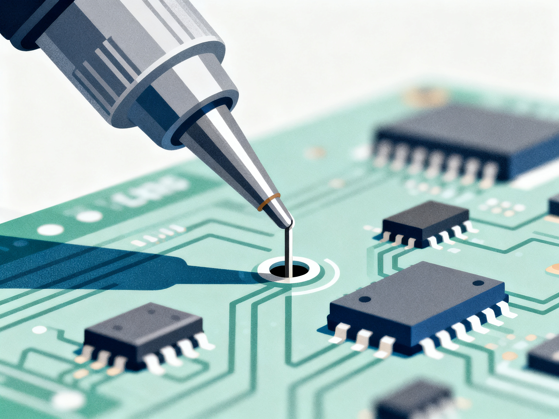
The big difference from traditional wave soldering? Wave soldering floods the entire bottom of the board with solder. Selective soldering keeps everything else cool and clean. No molten solder touching your nearby SMD components, no thermal stress on parts that can’t handle it.
This matters more than ever in 2026. Boards keep getting denser, and that heat-sensitive chip sitting right next to a through-hole connector? It stays safe.
The Selective Soldering Process: Step-by-Step Breakdown
The selective soldering process breaks down into four distinct phases. Each one matters, and skipping steps or rushing through them is where most problems start. Here’s what actually happens on the production floor.
Step 1: Flux Application
Flux gets sprayed onto the board first. The machine uses programmable nozzles to place tiny amounts exactly where you need them. Drop jet fluxers can hit spots as small as 2-4mm wide, which is crucial when your through-hole pins sit right next to SMD components.
We always recommend keeping at least 0.5mm clearance between your target pads and nearby surface-mount parts. Some engineers push for tighter spacing, but honestly? That’s when bridging starts becoming a problem. Better to give yourself room to work.
Step 2: Preheat Phase
The board heads into the preheat zone next. This gently warms everything up to around 100-130 degrees Celsius on the topside, depending on whether you’re using water-based or alcohol-based flux. The ramp rate stays under 2.8 degrees per second usually.
Why does this matter? Two reasons. First, it activates the flux so it can do its job properly. Second, it prevents thermal shock when molten solder hits cold metal. Nobody wants cracked components or cold joints, and a good preheat prevents both.
Pro Insight: Top-side and bottom-side selective soldering serve different purposes. Top-side soldering handles joints you can access from above, which works great for connectors and larger components. Bottom-side soldering is what you use when the board needs to stay flat and stable during processing. Most mixed-technology boards actually need both approaches, so look for equipment that can handle either method depending on your assembly complexity.
Step 3: Solder Application
Here’s where the magic happens. The molten solder, usually SAC305 alloy running around 280-320 degrees Celsius, gets forced through a dedicated nozzle to create a mini-wave or fountain. Only your target through-hole pins get hit. Everything else stays dry.
Dwell time usually runs between 1.5 and 3 seconds for standard joints. Thicker boards or heavy connectors might need more time, sometimes over 3 seconds. The key is getting enough heat into the joint for proper barrel fill without overdoing it and eating into your plated through-holes.
Step 4: Post-Solder Cleaning and Inspection
After soldering, excess flux residue needs to go. Some fluxes are designed to be left on, but others require cleaning, especially for automotive or medical applications. Then comes inspection: AOI systems catch visible problems like bridging or missing fillets, while X-ray gets used for hidden joints where you need to verify barrel fill.
The whole sequence, from flux to inspection, typically takes around 25 seconds per board for single-nozzle systems. Multi-nozzle setups can push that down significantly for high-volume work.
| Process Step | Key Parameter | Typical Range |
|————–|—————|—————|
| Flux Application | Wetting width | 2-4mm |
| Preheat | Topside temp | 100-130 degrees C |
| Solder Contact | Dwell time | 1.5-3.0 seconds |
| Solder Temperature | Pot temp | 280-320 degrees C |
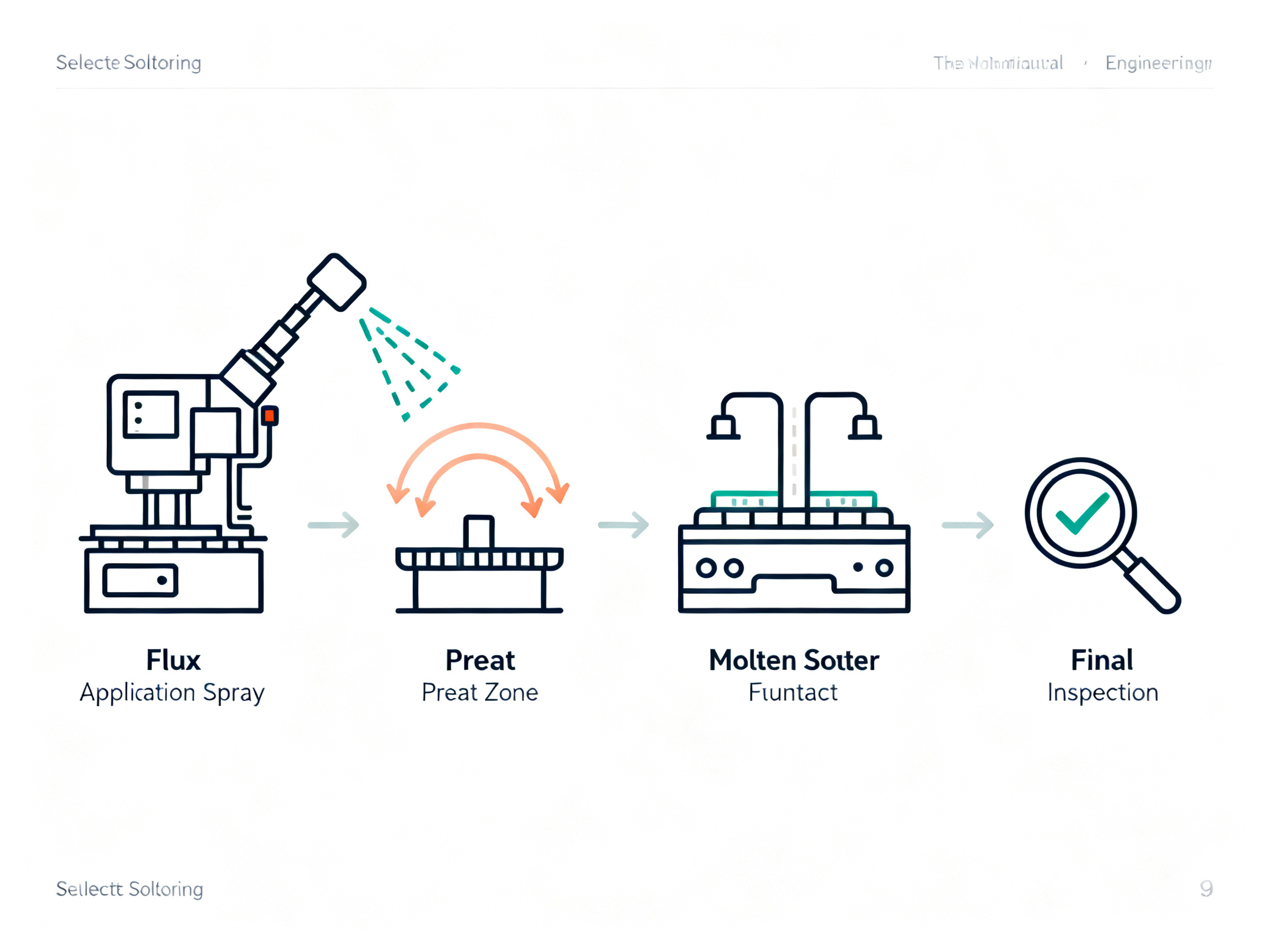
Getting these steps right matters. A well-tuned selective soldering process can hit defect rates as low as 25-80 DPMO, which is exactly what automotive manufacturers need to meet that strict 20 ppm benchmark.
Key Selective Soldering Techniques Compared
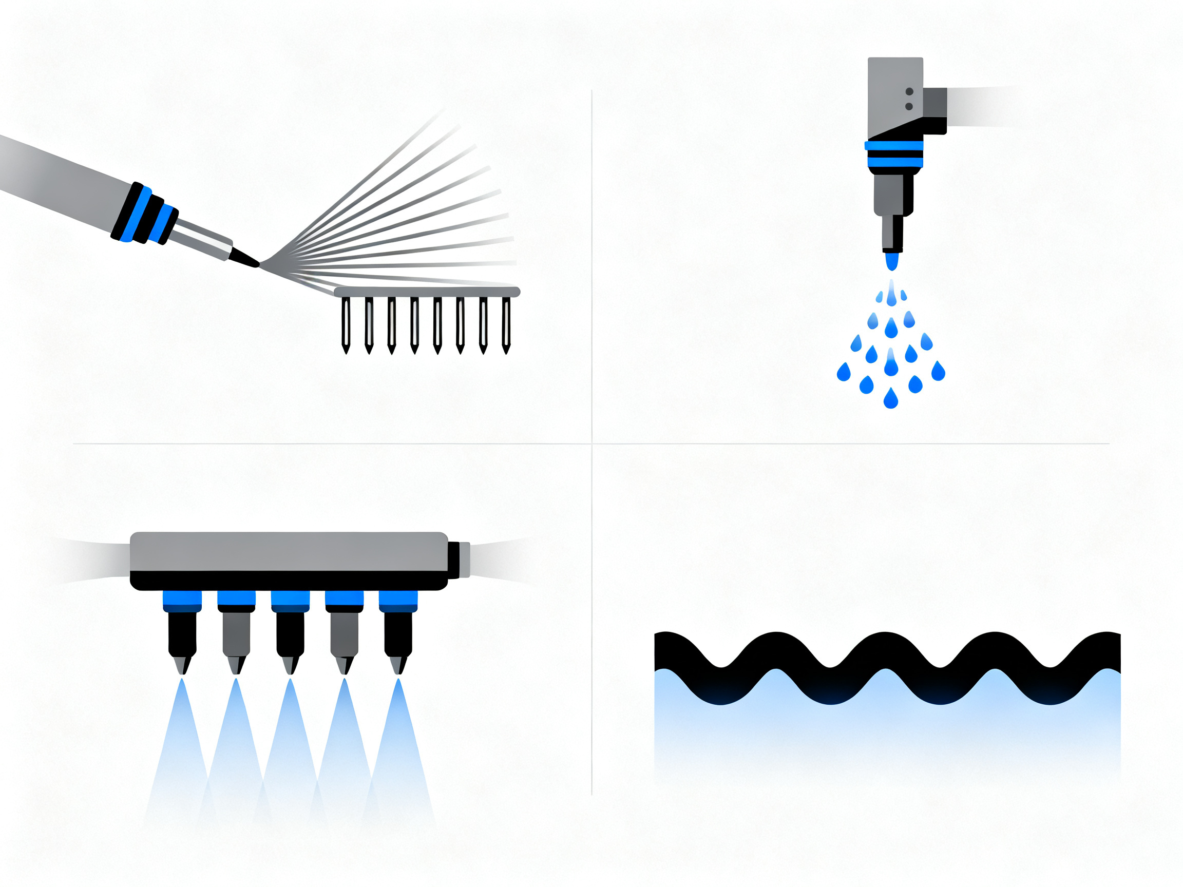
Not all selective soldering works the same way. Depending on your board design, production volume, and quality targets, different techniques will serve you better. Here’s what you actually need to know about the four main approaches.
Drag Soldering
This is where the nozzle literally drags across a row of pins, like painting them with solder one by one. It works best for components with multiple aligned leads, like DIP switches or memory slots. The motion creates a consistent wave front that wets each pin as it passes.
Thing is, drag soldering requires good clearance between your target pins and nearby components. If you’ve got tight spacing, the nozzle might not fit without risking contact with adjacent parts. We see this trip up a lot of teams who design boards without thinking about soldering access.
Drop Jet Soldering
Drop jet takes the precision angle to the extreme. Instead of dragging, the system shoots tiny solder droplets exactly where you need them. Individual pins get their own targeted application, which means this technique shines in high-mix, low-volume production.
This is what you want when every board in a batch might have different through-hole requirements. The flexibility is genuine. Modern drop jet systems hit spots as small as 2-4mm wide, and repeatability sits around 0.05mm on well-maintained equipment. That accuracy matters when you’re working with 0.5mm clearance zones next to expensive surface-mount chips.
Multi-Nozzle Parallel Soldering
Got high-volume demands? This is where selective soldering catches up to wave soldering’s throughput. Multiple nozzles work simultaneously, each handling different sections of the board. Systems like the SEHO Synchro 5 run five independent solder pots for concurrent processing.
You’re looking at 50 to over 100 boards per hour with this setup, compared to 20-50 boards with single-nozzle systems. The tradeoff is fixture complexity. Multi-nozzle work needs pallets configured for your specific board layout, which adds upfront cost and changeover time for new products.
Dip Soldering
Dip soldering drops pins directly into a stationary solder wave. It’s simpler mechanically than drag or jet approaches and handles specific geometries well, particularly for bottom-side components where the board orientation helps with drainage.
Dwell times run longer here, usually around 5 seconds at 265-270 degrees Celsius. That extra contact time helps topside fillet formation for lead-free alloys, which can be trickier than tin-lead to get looking right.
Pro Insight: Top-side and bottom-side selective soldering serve different purposes. Top-side soldering handles joints you can access from above, which works great for connectors and larger components. Bottom-side soldering is what you use when the board needs to stay flat and stable during processing. Most mixed-technology boards actually need both approaches, so look for equipment that can handle either method depending on your assembly complexity.
| Technique | Best Use Case | Throughput | Precision Level | Typical Applications |
|———–|—————|————|—————–|———————|
| Drag Soldering | Multiple aligned leads | 20-50 boards/hour | Medium-High | DIP switches, memory slots, connectors |
| Drop Jet Soldering | High-mix, low-volume | 20-50 boards/hour | Very High | Complex mixed-tech boards, prototyping |
| Multi-Nozzle Parallel | High-volume production | 50-100+ boards/hour | Medium-High | Automotive modules, consumer electronics |
| Dip Soldering | Bottom-side components | Variable | Medium | Heavy connectors, specific geometries |
Choosing the right technique isn’t just about speed. It’s about matching your board design, your volume reality, and your quality targets. A well-tuned drop jet system will outperform a poorly configured multi-nozzle setup every time.
Essential Guidelines for Setting Up Your Selective Soldering System
Getting your selective solder system dialed in correctly from the start saves you a ton of headaches down the road. Here’s what actually matters when you’re setting up a new line or fine-tuning an existing one.
Pallet Design Matters More Than Most People Think
Your pallet isn’t just something to hold the board. It masks everything that should not touch solder. That means all your SMD components, connectors, and any heat-sensitive parts need complete protection from the solder fountain.
We always recommend building pallets with at least 2mm clearance around masked areas. Some engineers try to squeeze tighter, but here’s what happens: vibration during processing, slight board flex, or thermal expansion can cause the board to shift just enough for disaster. The cost of reworking a board with solder damage to a $40 chip far exceeds the cost of proper pallet design from day one.
Flux Selection: Keep It Simple
For lead-free applications in 2026, low-solid-content no-clean fluxes are the standard choice. They minimize post-solder cleaning requirements, which cuts down your process steps and handling. Water-based fluxes work well but typically need higher preheat temperatures (100-130 degrees Celsius topside) compared to alcohol-based options (88-110 degrees Celsius).
The solid content matters because excess flux can spread beyond your target zone and create bridging problems, especially when you’ve got tight clearances between through-hole pins and nearby SMDs.
Temperature Profile: Slow and Steady
Your preheat ramp rate should stay under 2.8 degrees per second. Going faster risks thermal shock to components and inconsistent flux activation. Going slower is fine if your board can handle the time. For thick boards (3.2mm and above), you’ll need to push preheat temperatures toward the higher end of your flux’s recommended range to compensate for thermal mass.
Nozzle Selection: Match It to the Job
Nozzle diameter should closely match your pin size plus a small margin for solder flow. Too large and you risk bridging. Too small and you won’t get proper barrel fill. For standard through-hole pins (0.6-0.8mm diameter), a 3-4mm nozzle typically works well. For larger connectors or heavy thermal loads, you might need 5mm or custom geometries.
From Our Experience: The most common pitfall when transitioning from legacy wave soldering is underestimating how much process development work selective soldering requires. Wave soldering is forgiving because it treats everything the same. Selective soldering rewards precision. Budget time for program development, fixture iteration, and process qualification before you commit to production schedules. Teams that rush this phase typically spend 3-5x more time debugging defects than they saved by skipping the setup work.
System Setup Checklist
Before running production, verify these parameters:
- [ ] Pallet clearance: minimum 2mm around masked components
- [ ] Flux type matches your board finish requirements
- [ ] Preheat ramp rate: under 2.8 degrees per second
- [ ] Nozzle geometry matched to pin size and pitch
- [ ] Nitrogen atmosphere: oxygen below 50 ppm (ideally sub 10 ppm)
- [ ] Solder pot temperature: 280-320 degrees Celsius for SAC305
- [ ] Dwell time validated for your specific board thickness
- [ ] AOI and X-ray inspection ready for post-solder verification
Take time on this setup phase. A well-configured system consistently hits 25-80 DPMO. A rushed setup struggles to beat 200 DPMO. That gap shows up directly in your rework costs and delivery timelines.
Common Selective Soldering Defects and Prevention Strategies
Even the best selective soldering systems will spit out defective joints if something goes sideways during setup or operation. Knowing what to look for, and more importantly, knowing how to fix the root cause, separates the operators who spend their days reworking boards from the ones who ship clean assemblies.
Solder Bridging
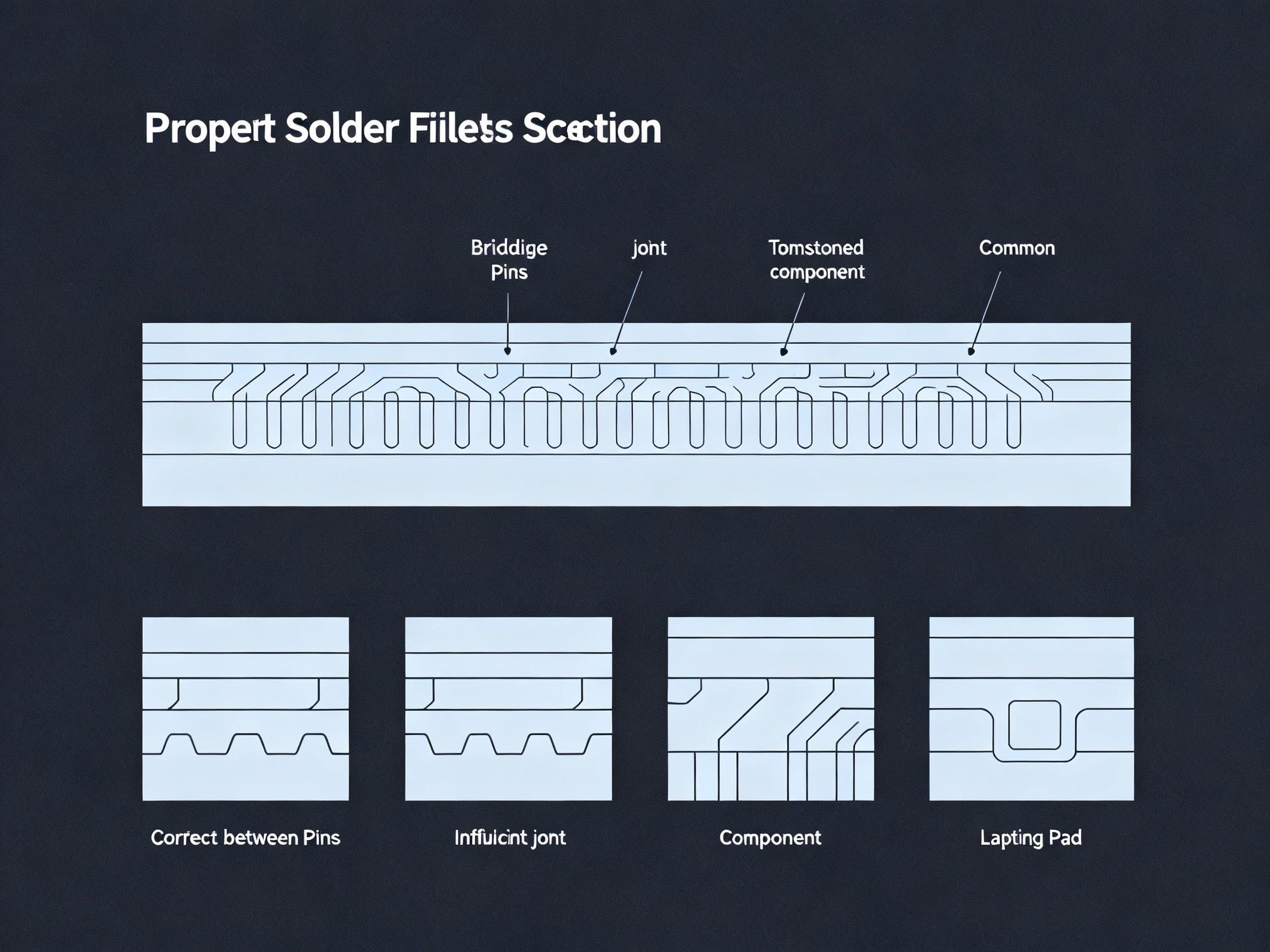
This is probably the most common defect you’ll encounter. Bridging happens when solder forms an unwanted connection between adjacent pins, creating a short that will absolutely kill functionality. The usual suspects are excessive solder volume, nozzle size mismatch, or masking that doesn’t quite cover the adjacent pads. We’ve seen bridging spike when operators use nozzles that are too large for the pin spacing, or when flux gets everywhere instead of staying where you put it.
The fix is usually straightforward: match your nozzle diameter to your pin size, verify pallet masking covers adjacent areas with at least 2mm clearance, and dial in your flux quantity. Also, keep an eye on your board-to-nozzle parallelism. A tilted board can cause solder to flow where it shouldn’t.
Insufficient Solder Fillets
If your joints look scrawny or the hole didn’t fill properly, you’re probably dealing with insufficient preheat, short contact time, or inadequate solder temperature. Lead-free SAC305 alloys need more heat energy than tin-lead did, so don’t expect to run the same parameters. For standard through-hole joints, you’re looking at 1.5 to 3 seconds of dwell time. Heavy connectors or thick boards might need over 3 seconds.
Tombstoning
This is when a component lifts off the pad during soldering, leaving one side connected and the other floating. Uneven heating usually causes it, where one pad gets hotter than the other and pulls the component over. Excessive flux activity can make it worse. Check your preheat uniformity and make sure both pads of any through-hole component see similar thermal conditions.
Lifted Pads
Nobody wants to see a pad that decided to separate from the board. This typically comes from excessive thermal stress or a board that wasn’t built to handle the heat. Thick boards with large copper planes act as heat sinks, pulling heat away from the joint and potentially stressing the plating. If you’re seeing lifted pads, back off your temperatures or dwell times, and check whether your board manufacturer needs to spec thicker copper plating.
Expert Tip: Real-world data shows manual soldering runs 1,000 to 5,000 DPMO, while automated selective soldering gets you down to 50 to 200 DPMO. Well-tuned systems hit 25 to 80 DPMO. If your defect rates are staying above 200 DPMO despite good equipment, the problem is usually process tuning, not the machine itself. Bridging specifically responds well to tighter nozzle matching, reduced flux spread, and checking that your target clearances stay above 0.5mm between through-hole pads and nearby SMD components.
Defect Identification Quick Guide
| Defect Type | Visual Clue | Primary Cause | Quick Fix |
|————-|————|—————|———–|
| Bridging | Solder connecting two pins | Excess solder, bad masking | Smaller nozzle, better masking |
| Insufficient Fillet | Scrawny joint, poor hole fill | Short dwell, cold temps | Increase time and temperature |
| Tombstoning | Component tilted or lifted | Uneven heating | Check preheat uniformity |
| Lifted Pad | Pad separated from substrate | Thermal stress, poor base material | Lower temps, check board quality |
Catching these defects early through regular AOI and periodic X-ray inspection will save you from expensive rework down the line. Set up your inspection schedule based on your defect history. If bridging keeps showing up, inspect every board. If your process is stable, sampling inspection might be enough.
Selective Soldering vs. Alternative Methods: When to Choose Selective Soldering
So when does it actually make sense to pick selective soldering over the other options out there? Let’s break this down in practical terms.
Hand Soldering vs. Selective Soldering
If you’re making fewer than 50 boards per month and they change constantly, hand soldering might still make sense. The equipment cost is basically zero, and you can adapt on the fly. But here’s the thing: once you cross that 50-unit threshold, selective soldering starts winning on economics alone. You get consistency that humans just cannot match, and your defect rates drop from the 1,000 to 5,000 DPMO range down to 50 to 200 DPMO. For automotive work where the standard sits at 20 ppm, this isn’t optional. It’s required.
Wave Soldering vs. Selective Soldering
Wave soldering is fast and cheap per board, but it treats your entire board the same way. That works when you have open, simple designs with no nearby SMD components. But modern assemblies? They’re packed tight. Wave soldering means you’re either damaging heat-sensitive parts or designing around massive keep-out zones. Selective soldering eliminates those mask-related setup headaches and cuts consumable waste because you’re only using solder exactly where needed.
Reflow Soldering vs. Selective Soldering
Through-hole joints in reflow often don’t get the mechanical strength you need. The solder simply doesn’t wick into the barrel properly without real contact with molten metal. Selective soldering creates proper barrel fill and strong mechanical joints that reflow just cannot match for through-hole work.
The Economic Reality
Here’s a quick way to think about it. If you’re running over 10,000 boards per month with meaningful through-hole content, selective soldering typically pays for itself in 12 to 24 months through labor savings and defect reduction. The math gets fuzzy below that volume unless your quality requirements are strict.
| Method | Best For | Defect Rate | Throughput | Setup Complexity |
|——–|———-|————-|————|——————|
| Hand Soldering | Prototypes, under 50 units | 1,000-5,000 DPMO | Low | Minimal |
| Wave Soldering | Simple, open boards | 500-2,000 DPMO | Very High | Medium |
| Reflow (TH joints) | SMT-dominant, limited TH | Variable | High | Low |
| Selective Soldering | Complex mixed-tech boards | 25-200 DPMO | Medium-High | Medium-High |
The choice really comes down to your board complexity and volume. Dense mixed-technology assemblies with quality targets below 100 DPMO? Selective soldering is your only real option in 2026. Simple boards with plenty of spacing and moderate quality needs? Wave soldering might still win on speed and cost.
Optimizing Your Selective Soldering Process for High-Volume Production
Getting your selective solder system to perform at high volume takes more than just running boards through as fast as possible. Here’s what actually works on the production floor.
Program Optimization
Your toolpath matters more than most people realize. Every extra movement wastes cycle time. We recommend mapping out your solder sequence so the nozzle travels the shortest path between joints, and position boards to minimize repositioning. Z-height settings also need fine-tuning for your specific board thickness. Setting the nozzle too high means poor solder contact. Too low and you risk damaging components or creating excess cleanup work. Most operators find their sweet spot around 0.5 to 1.0mm above the board surface for standard 1.6mm boards.
Batch Processing
Running similar boards back-to-back cuts down changeover significantly. Group assemblies by component layout rather than production order when you can. If you’re processing automotive control modules followed by consumer electronics boards, you’re resetting fixturing and reprogramming between each batch. Stick with similar designs to keep momentum going.
Predictive Maintenance
Solder pot dross builds up faster than you think, especially with SAC305 alloys running at 280 to 320 degrees Celsius. Check levels daily and clean out accumulated oxidation every two weeks. Nozzle wear happens gradually, and you won’t see bad joints until you’ve already produced a bunch of them. Keep track of nozzle usage hours and inspect tips regularly for erosion.
Quality Integration
Connecting your selective solder system to your AOI and MES gives you real-time feedback loops that manual inspection just cannot match. When bridging shows up on the optical check, that data goes straight back to adjusting your program parameters. Traceability logs also mean you know exactly which board had which issue, which matters a lot when customers come asking questions.
From Our Experience: The most common pitfall when transitioning from legacy wave soldering is underestimating how much process development work selective soldering requires. Wave soldering is forgiving because it treats everything the same. Selective soldering rewards precision. Budget time for program development, fixture iteration, and process qualification before you commit to production schedules. Teams that rush this phase typically spend 3-5x more time debugging defects than they saved by skipping the setup work.
Best Practices Summary for Production Managers
| Optimization Area | Key Action | Frequency | Impact |
|—|—|—|—|
| Toolpath | Map shortest solder sequence | Per program | 10-20% cycle time reduction |
| Z-height | Set based on board thickness | Per setup | Consistent joint quality |
| Batch grouping | Group by assembly layout | Per shift | Reduced changeover time |
| Solder pot | Check levels, clean dross | Daily/weekly | Stable temperature control |
| Nozzle inspection | Check for wear and erosion | Weekly | Prevent defect escapes |
| MES integration | Enable real-time defect tracking | Always on | Faster response to issues |
The operators who get the best results treat selective soldering like a sport. Small improvements in program efficiency, maintenance discipline, and data integration add up fast. A well-optimized line hits 50 to 100+ boards per hour consistently, and defect rates stay in that 25 to 80 DPMO range that keeps automotive customers happy.
Conclusion: Key Takeaways and Implementation Recommendations
Selective soldering has moved from nice-to-have to essential in 2026. Boards keep getting denser, quality standards keep getting tighter, and the economics of manual soldering just don’t make sense anymore for most production volumes.
Here’s what matters most:
The precision pays off. When you compare 1,000 to 5,000 DPMO from hand soldering against 25 to 80 DPMO from a well-tuned selective solder system, the math is pretty simple. For automotive work where 20 ppm is the benchmark, selective soldering isn’t optional. It’s the only realistic path to get there.
Setup quality determines everything. We keep seeing teams rush the programming and fixture development phase, then wonder why their defect rates stay high. The equipment is capable, but it rewards precision. Budget the time upfront to get your parameters right, and you’ll save way more time on the backend dealing with escapes and rework.
Technique selection matches your reality. Drop jet for flexibility and high-mix work. Multi-nozzle for volume. Drag soldering when geometry cooperates. There’s no single right answer, just the answer that fits your board designs and production cadence.
Integration multiplies the value. Connecting your selective solder system to AOI, X-ray inspection, and MES tracking creates feedback loops that manual processes simply cannot match. Real-time data means faster responses to issues and better traceability when customers come asking questions.
Bottom line: If you’re still running complex mixed-technology assemblies through hand soldering or blanket wave processes, you’re accepting defect rates that modern electronics manufacturing simply cannot tolerate. The equipment investment pays back through quality improvements, labor savings, and reduced rework. Talk to specialists who understand your specific production context and quality targets. The right selective soldering setup for your operation exists, and finding it is worth the effort.
Quick Reference: Key Selective Soldering Stats
- Manual soldering: 1,000 to 5,000 DPMO
- Standard selective soldering: 50 to 200 DPMO
- Optimized selective soldering: 25 to 80 DPMO
- Automotive benchmark: 20 ppm
- Typical ROI timeline: 12 to 24 months
- Throughput range: 20 to 100+ boards per hour
- Preheat ramp rate: Under 2.8 degrees per second
- SAC305 operating temp: 280 to 320 degrees Celsius
For manufacturers evaluating their SMT soldering capabilities in 2026, the selective soldering question isn’t whether anymore. It’s how fast you can implement it.