You can lower thermal stress in selective wave soldering by using preheating, temperature control, and selective heating.
-
Preheating slowly warms up the PCB. This stops thermal shock and helps keep parts from cracking or lifting.
-
If you skip preheating, you might get problems like not enough hole fill or lifted parts because the temperature is not steady.
-
Good temperature control makes sure the board gets hot enough before the solder wave. This helps make better solder joints and lowers the chance of parts failing.
Key Takeaways
-
Warm up the PCB slowly between 100°C and 150°C. This helps stop thermal shock. It also keeps parts from cracking or lifting.
-
Watch solder wave settings like temperature, wave height, and dwell time. This makes strong solder joints. It also helps stop damage.
-
Use thermal barriers and pick flux with care. This keeps sensitive parts safe. It also helps solder flow better.
-
Check the soldering process in real time with sensors and cameras. This helps find problems early. It also keeps quality high.
-
Design your PCB with thermal reliefs and balanced copper. This spreads heat evenly. It helps stop warping or hot spots.
Thermal Stress Basics

Causes
Thermal stress happens when parts on your PCB get bigger or smaller at different speeds. Each material, like the chip, solder, and copper, changes size in its own way. This is because each one has a different coefficient of thermal expansion (CTE). When you heat the board, these differences cause stress where the materials meet. The most stress happens between the chip and the solder. Heating and cooling the board many times makes the stress worse. Cracks can start at the chip–solder spot after several cycles. If you pick solder with a CTE close to the chip, you can lower the stress and make the board last longer.
Selective wave soldering lets you control where the heat goes. It does not heat the whole board like traditional wave soldering. Instead, it heats only the spots that need soldering. This keeps the rest of the board cooler. It also protects parts like connectors and ICs. By not dipping the whole board in hot solder, you lower the heat on the board. This helps keep SMT parts safe.
Effects
Thermal stress can cause many problems for solder joints and parts. Here are some common effects:
-
Solder joints can crack, mostly where the solder meets the chip.
-
The intermetallic compound (IMC) layers in the solder can get thicker and more brittle, which makes joints weaker.
-
Solder joints do not last as long when the board gets hot and cold a lot.
-
Electronic devices can fail, and about 70% of these failures are from packaging and assembly problems, often because of thermal failure in solder joints.
-
Smaller solder joints and lead-free solders can make these problems worse by making IMC grow faster.
Tip: You can make your board more reliable by watching temperature cycles and picking materials with similar CTE values.
Key Factors
Temperature Profile
It is important to watch the temperature profile during selective wave soldering. This helps keep your PCB and its parts safe. Preheating the board between 100°C and 150°C for 60 to 120 seconds is helpful. It lowers thermal shock and gets the flux working. This step gets the board ready for soldering. It also makes sure the flux can clean off oxides. If you heat the board slowly, at 1–3°C per second, you avoid quick changes in temperature. Fast changes can cause thermal stress.
Here is a table with the best temperature profile settings:
|
Temperature Profile Parameter |
Recommended Range / Description |
|---|---|
|
Preheat Temperature |
100°C to 150°C |
|
Solder Bath Temperature |
250°C to 300°C |
|
Cooling Rate |
2–4°C per second |
|
Nitrogen Environment |
250°C–270°C for void-free joints |
|
Temperature Monitoring |
Use thermocouples or IR sensors |
|
Equipment Calibration |
Regular calibration |
Note: Cooling the board at 2–4°C per second stops the PCB from bending. It also keeps solder joints strong.
Dwell Time
Dwell time is how long the board touches the solder wave. You need to watch this time closely. If the board stays in the solder too long, it can hurt sensitive parts. Things like bond wire lifting, die damage, or melting plastic can happen. Longer dwell times mean more heat, which raises thermal stress. Use the lowest temperature that lets you solder in just a few seconds. This keeps dwell time short. Letting the board cool between joints stops heat from building up.
-
Too much dwell time means more chance of damage.
-
Too little dwell time means weak solder joints.
-
You need to find the right amount of time for your board.
Component Sensitivity
Some parts are more sensitive to heat than others. Always check the specs for each part before you solder. Change the soldering speed and equipment temperature for your most sensitive parts. If the temperature is too high, solder joints can get brittle or the board can crack. If the temperature is too low, solder may not flow well. This can make weak joints. Good temperature control and careful work help stop solder bridging and other problems. This keeps thermal stress as low as possible.
Minimizing Thermal Stress
Preheating
You can lower thermal stress by heating the PCB slowly. Warm the board before it touches the solder wave. This helps the flux clean the metal and makes solder flow better. Preheating also stops thermal shock, which can break parts or hurt solder joints. Keep the preheat temperature between 105°C and 145°C for best results. Hold the board at this heat long enough for the flux to work, but not so long that it burns.
Tip: Preheating helps the flux work and heats the board evenly. This keeps sensitive parts safer during soldering.
Solder Wave Control
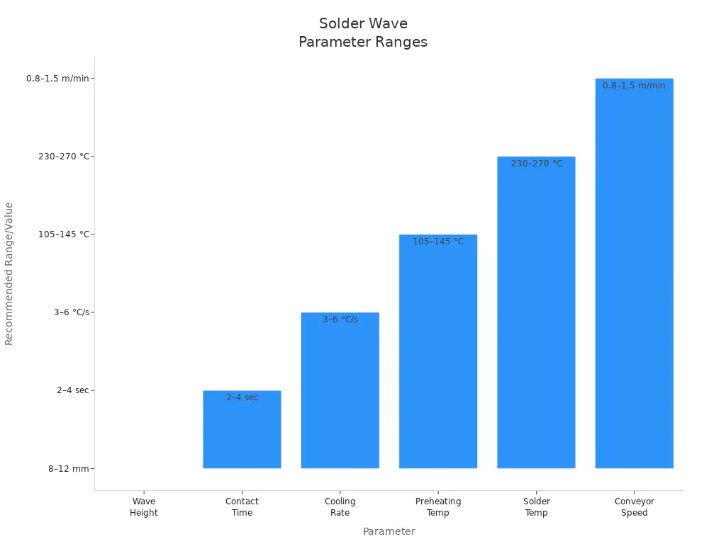
You must control the solder wave to keep thermal stress low. Change the wave height, contact time, and solder temperature for your board. Use sensors and check often to keep these settings steady. The table below shows the best ranges for each setting:
|
Parameter |
Recommended Range/Value |
Purpose/Effect on Thermal Stress and Solder Quality |
|---|---|---|
|
Wave Height |
8–12 mm |
Makes sure pads touch the solder but do not splash; too low means open circuits, too high means splatter and bridging. |
|
Contact Time |
2 sec (small components), 4 sec (large through-hole) |
Gives enough time for soldering without too much heat, balancing wetting and thermal stress. |
|
Cooling Rate |
3–6 °C/s |
Fast but steady cooling stops thermal stress and cracks; too fast causes stress, too slow makes weak joints. |
|
Preheating Temp |
105–145 °C |
Activates flux and stops thermal shock; too low means flux does not work, too high burns flux and causes oxidation. |
|
Solder Temp |
Lead-free: 250–270 °C; Leaded: 230–250 °C |
Matches the solder melting point so parts do not get damaged. |
|
Conveyor Speed |
0.8–1.5 m/min (varies by PCB complexity) |
Controls how long the board is in the solder wave; too fast means cold joints, too slow means overheating and color change. |

-
Use solder with a coefficient of thermal expansion close to your board.
-
Pick a slow, steady cooling rate to stop cracks.
-
Change all settings for your board and equipment.
-
Use nitrogen to stop oxidation and make solder better.
Note: For multilayer boards, use rotating thermal reliefs and keep them at least 0.4 mm. This helps lower Z-axis stress and stops the board from bending.
Thermal Barriers
Thermal barriers protect sensitive parts from too much heat. You can use shields made from aluminum or ceramics to block heat. Temporary covers or lids hold back heat until the board is ready. These methods help all parts heat up at the same speed, which lowers thermal stress.
-
Shields and barriers keep heat away from delicate parts.
-
They help the board heat up more evenly.
-
You avoid fast or uneven heating, which can cause cracks or weak joints.
Alert: Always check that your thermal barriers fit well and do not block the solder wave from reaching the pads.
Flux Selection
Picking the right flux is important for lowering thermal stress. Choose a flux with the right activity level for your temperature. Check the solids content because it affects how the flux works with heat. Make sure the flux matches your board and parts to stop damage.
-
Pick flux based on activity level for good activation.
-
Check the solids content for good performance with heat.
-
Make sure the flux works with your board and parts.
Tip: Preheating helps the flux work better, lowers thermal shock, and helps solder stick. This step makes strong, reliable joints.
Process Control
Monitoring
It is important to watch your selective wave soldering process as it happens. Modern machines use special tools to check temperature, wave height, and nitrogen flow. These tools help you find problems before they hurt your boards. When you get feedback right away, you can change settings fast. This keeps the process steady and easy to repeat.
Here is a table with some of the best monitoring systems and what they do:
|
Temperature Monitoring System |
Description |
Contribution to Process Reliability |
|---|---|---|
|
Optical Pyrometer |
Measures the real PCB temperature and uses closed-loop control |
Gives exact temperature readings and feedback for steady soldering quality |
|
Nitrogen Flow Digital Monitoring |
Checks nitrogen pressure and flow to keep the solder pot level and temperature steady |
Keeps solder pot conditions steady and repeatable, better than old probes |
|
Super-Heated Nitrogen Path |
Warms up nitrogen inside the solder pot and along the solder path |
Stops temperature changes in the solder wave, making the process more stable |
|
Wave Height Monitoring |
Uses resistive checks and closed-loop feedback to keep wave height within ±0.005-in. |
Needed for soldering small, close-together parts with high accuracy |
|
PID Temperature Control |
Controls solder wave crest temperature from 0-400°C with closed-loop servomotor tech |
Gives accurate, repeatable temperature control and placement during soldering |
|
Soldering Vision System |
Watches and records the soldering process in real time |
Helps track the process and check quality right away |
|
Top-Side Preheating |
Keeps the board warm during soldering, good for heavy boards |
Makes heat spread better and helps solder stick, giving steady results |
You can also use cameras and alarms that work in real time. These tools help you spot problems quickly and keep things running smoothly.
Validation
You need to check your process to meet quality rules and make sure solder joints are strong. Validation means checking every step, from the materials to the machine settings. Start by making a process flow chart and looking for possible failures. Test your process at both the lowest and highest settings for temperature, flux, and conveyor speed. This shows if your process works in all situations.
|
Recommended Procedure / Consideration |
|
|---|---|
|
Process Variables |
Track and write down solder type, flux type and use, bath and zone temperatures, wave height, and conveyor speed. |
|
Process Flow Analysis |
Begin with a Process Flow Diagram (PFD) and a Process Failure Mode Effects Analysis (pFMEA) to find key risks. |
|
Validation Trials |
Test process settings at the hardest limits (like low/high temperatures, flux amounts, chain speeds) to check quality. |
|
Inspection Methods |
Use visual checks and X-ray scans to verify, but not just for validation. |
|
Continuous Monitoring |
Always record process settings and compare them to good ones for better control. |
|
Sample Size & Criteria |
Use experience or math methods; check first samples by eye and test all for function. |
|
Operator Qualification |
Make sure operators are trained, certified, and checked for quality as part of validation. |
|
Qualification Phases |
Use Installation Qualification (IQ), Operational Qualification (OQ), and Performance Qualification (PQ). |
Tip: Watching and checking your process all the time helps you find problems early. This keeps your process strong and your products safe.
PCB Design

Layout Tips
You can make your PCB handle heat better by making thermal zones. These zones help the board warm up slowly and evenly. Use thermal relief vias in power planes to move heat away from hot spots. This keeps the board from getting too hot. Put parts with different heat needs in separate areas. This protects sensitive parts from too much heat. Run thermal stress modeling early in your design. This helps you find and fix hot spots before building the board.
Here are some layout strategies to help manage heat:
-
Add thermal reliefs to connect pads to planes for better heat flow.
-
Balance copper on the board to stop warping and twisting.
-
Use copper pours and thieving to spread heat evenly.
-
Check your design with simulation tools to find thermal problems.
Tip: Use pallets or fixtures during soldering to support the board and stop warping.
Component Choice
Pick parts that can handle the heat of selective wave soldering. Most lead-free parts need to take 250°C to 260°C. Always check the highest temperature each part can take, especially for electrolytic capacitors and microcontrollers. Use thermal profiling tools to set the right temperature for your most sensitive parts. Choose board thickness and copper weight to match your heat needs. Thicker boards may need higher preheat temperatures for even heating.
-
Pick parts with high heat tolerance.
-
Place sensitive parts away from the hottest areas.
-
Program solder nozzle movement to limit heat on delicate parts.
-
Use flux and preheat based on what each part needs.
Common Mistakes
Many designers make mistakes that can damage the board during soldering. Avoid these common errors:
-
Not doing thermal profiling, which causes uneven heating and cooling.
-
Picking PCB materials with poor thermal properties or mismatched expansion rates.
-
Putting parts too close together, which traps heat and makes hot spots.
-
Using wrong hole sizes for through-hole parts, which makes weak solder joints.
-
Setting soldering temperatures or times too high or too low, which causes pad damage or cold joints.
You can stop these problems by running thermal simulations, using the right heating profiles, and keeping your equipment in good shape.
You can get good selective wave soldering by watching the process closely and designing your PCB well. Use real-time monitoring to help you spot problems fast. Keep the wave height, flux, and temperature in the right range. This helps stop mistakes and makes solder joints strong. Preheating the board helps protect parts. Using nitrogen and setting the conveyor speed right also helps solder stick better. Watch important numbers and change settings quickly if you see a problem.
If you follow these tips, you will have fewer mistakes, save energy, and your boards will last longer.
FAQ
What is the best way to prevent thermal shock during selective wave soldering?
You should preheat your PCB slowly. This helps the board and parts warm up together. Preheating stops cracks or lifted pads from quick temperature changes.
How do you choose the right flux for selective wave soldering?
Pick flux that works with your soldering temperature and board. Look at the activity level and solids content. The right flux helps solder flow and lowers thermal stress on sensitive parts.
Why does dwell time matter in selective wave soldering?
Dwell time means how long your board touches the solder wave. Too much time gives too much heat and can hurt parts. Too little time makes weak solder joints. You need to find the best time for your board.
Can you use selective wave soldering for all PCB types?
You can use selective wave soldering for most through-hole and mixed boards. Very packed or heat-sensitive boards need extra care. Always check part specs and do thermal profiling first.
