
Published: 11 November 2026
Last Updated: 11 November 2026
Reading Time: 13 minutes
Reviewed By: [Reviewer Name, insert before publication], [Reviewer Credentials, insert before publication]
Author: S&M Co. Ltd. Engineering Team, Shenzhen Chuxin Electronic Equipment Co., Ltd.
Disclosure: This article was written by engineers who design and build lead-free reflow ovens, wave soldering machines, and complete SMT production lines. We make the equipment, so we have a stake in what we tell you. We have kept the process data honest, flagged where the published research is thin, and told you where the numbers come from.
Note for the editor: insert the reviewer name and credentials above before publishing.## What Is Nitrogen Reflow Soldering? A Direct Answer
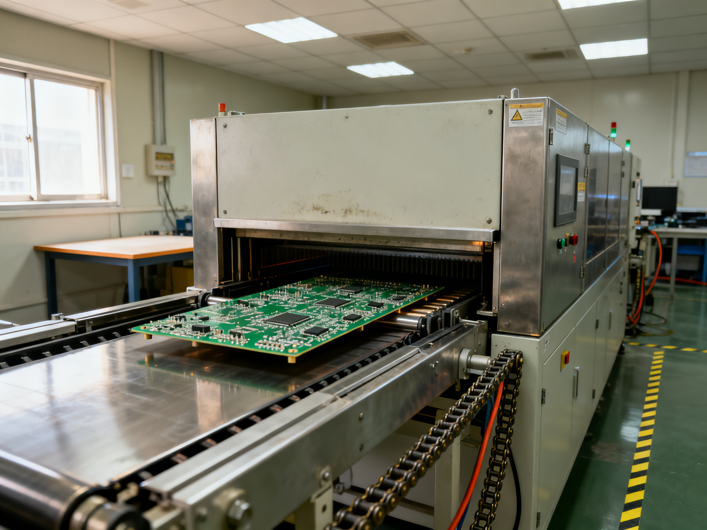
Here is the short answer. Nitrogen reflow soldering is reflow soldering done inside a sealed chamber filled with high-purity nitrogen gas instead of ordinary room air. The soldering cycle itself does not change. The air around your board does, and that changes a lot.
Think about what reflow soldering actually is. A machine heats a printed circuit board until the solder paste melts, then lets it cool so the solder forms a solid joint between the component and the pad. That is the whole idea. The board moves through zones, the temperature rises in steps, and somewhere in the middle the alloy goes liquid for a few seconds before it freezes into place. If you want the mechanics in plain terms, this explainer on how reflow soldering works covers the basics.
Nitrogen reflow keeps that same sequence. It just swaps the air for an inert gas with almost no oxygen in it, usually held at or below 1,000 parts per million.
Definition: Nitrogen reflow soldering means the full cycle, preheat, soak, liquidus, and cooling, runs inside a sealed chamber purged with high-purity nitrogen, holding oxygen at roughly 1,000 ppm or less to limit oxidation during heating.
Where the nitrogen sits in the cycle
Preheat  ->  Soak  ->  Liquidus  ->  Cooling
  ~150C      ~200C     ~245-260C      controlled
   |          |          |            |
   └──────────┴──────────┴────────────┘
        Sealed chamber, nitrogen at every stage
Every stage matters. Oxidation does most of its damage in the soak and liquidus window, when the solder is hot enough to react with air but not yet flowing.
Why line builders care
For dense BGA and QFN assemblies in consumer electronics, semiconductor packaging, and military programs, the gap between air and nitrogen often shows up as the difference between a board that passes first inspection and a board that goes to rework or the scrap bin. Oxygen drives the oxide skin that hurts wetting, and wetting is what lets a small ball or a tight thermal pad bond cleanly.
IPC’s own study on improving joint quality with nitrogen found measurable joint improvements at oxygen levels of 2,000 ppm and below. Air Products testing reported better wetting and lower ionic contamination at 1,000 ppm.
That is the deal in one line: same solder, same board, same machine family, better atmosphere.
Next up, we look at why that one change moves the needle so much on the line.Photo: [Insert author photo], S&M Co. Ltd. Engineering Team
About the Author
This article was written by the engineering team at S&M Co. Ltd. (Shenzhen Chuxin Electronic Equipment Co., Ltd.), a manufacturer of lead-free reflow ovens, wave soldering machines, and complete SMT production lines. Our engineers design nitrogen atmosphere reflow oven systems and support production lines in consumer electronics, semiconductor packaging, and military electronics manufacturing every day.
That hands-on work shapes how we write. Instead of pulling numbers from a catalogue, we pulled them from oven logs, oxygen readings, and X-ray reports taken on customer lines. Where the published research is thin, such as controlled air-versus-nitrogen voiding comparisons for SAC305 at 245 to 260 °C, we say so instead of padding the gap with a guess.
The goal is simple: help you separate what nitrogen reflow soldering actually delivers from what gets marketed around it.
Company profile: S&M Co. Ltd. / Shenzhen Chuxin Electronic Equipment Co., Ltd.
Note for the editor: replace the author photo placeholder, confirm the writing team credit line, and insert reviewer name and credentials before publication.## How Nitrogen Reflow Soldering Works
A nitrogen reflow system does not heat a board differently from a conventional oven. It changes the atmosphere surrounding the board while the solder is molten. That distinction matters because the most consequential reactions during reflow happen at the interface between liquid solder, flux, component terminals, and oxygen.
1. The Board Enters the Reflow Zone
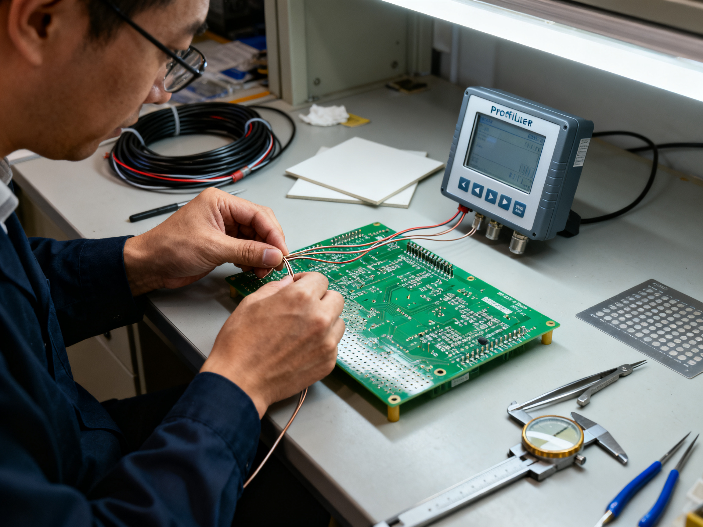
A typical reflow profile has four stages:
- Preheat brings the board and components toward the solder-alloy melting range slowly enough to drive moisture out and reduce thermal shock.
- Soak allows the solder paste to warm, melt, and wet the pads while fluxes activate and remove oxides.
- Liquidus holds the assembly at or above the alloy’s liquidus temperature, typically around 217 °C for SAC305. This is the stage where oxidation is most damaging.
- Cooling solidifies the solder and establishes the final joint shape.
Nitrogen is most useful during the liquidus and high-temperature portions of the profile, although some systems introduce it during preheat to establish a controlled atmosphere before the solder becomes fully molten.
2. Nitrogen Establishes an Oxygen-Controlled Environment
An atmosphere controller mixes nitrogen with either air or a small amount of forming gas to maintain a specified oxygen concentration. High-purity nitrogen can create a strongly inert environment, while nitrogen with forming gas offers additional reducing properties. The appropriate formulation depends on the process, the solder alloy, the flux, and the level of oxide control required.
The key specification is not simply whether the gas is called nitrogen. It is the measured oxygen level at the board. A gas supply advertised as high-purity nitrogen may still deliver unacceptable oxygen levels if its delivery system contains leaks, moisture, or poorly purged lines.
For that reason, oxygen monitoring and closed-loop control are important parts of a properly specified nitrogen reflow system. Operators should be able to verify conditions at the board rather than infer them from a cylinder label or flowmeter.
3. Flux Removes Oxides
Flux is still the active chemical cleaner at the joint. As the profile heats the assembly, flux softens and activates. It breaks down existing surface oxides on the pads and component terminations, allowing molten solder to spread across the metal surfaces.
Nitrogen does not make flux obsolete. Instead, it prevents the atmosphere from rapidly recreating oxides after flux has done its work. This gives flux more time to clean the interfaces and gives molten solder a cleaner surface to wet.
4. Molten Solder Wets the Joint
When a clean pad and termination meet molten solder, the solder forms a controlled meniscus between the surfaces. Good wetting means that the solder spreads outward, contacts the intended metal area, and produces a smooth, shiny fillet with a favorable contact angle.
In an oxygen-rich atmosphere, oxide films can form between flux activity and solidification. These films act as barriers, causing the solder to bead up or pull back. The result may look rough, dull, or insufficiently spread even when the board experienced an acceptable temperature profile.
With controlled oxygen levels, the solder can maintain a cleaner interface long enough to wet the pad and termination properly. The improvement is especially visible on fine-pitch packages, large thermal pads, and assemblies that spend a long time near liquidus temperature.
5. Cooling Solidifies a More Predictable Joint
Cooling does more than stop the chemical reactions. It controls the joint’s final geometry, microstructure, and stress distribution. Nitrogen can improve cooling consistency indirectly by reducing variations caused by oxidation, dross formation, and unstable solder wetting.
The objective is not simply a brighter joint. A well-formed joint should have adequate pad coverage, a smooth meniscus, limited voids, and a reliable mechanical connection. Appearance is useful for inspection, but it should never replace process measurements and electrical testing.
What the Nitrogen Atmosphere Does Not Do
Nitrogen will not compensate for an unsuitable solder paste, incorrect component placement, inadequate flux activation, or a defective thermal profile. It also does not prevent every defect. A board with insufficient paste volume can still produce an inadequate joint in nitrogen, and a profile that ramps too aggressively can still cause defects such as solder balls or cracked components.
The atmosphere is one part of the complete reflow process. It should be introduced after the oven, heater, profile, board-loading method, and component and material requirements have been evaluated.
How to Verify That Nitrogen Reflow Is Working
A successful installation requires more than switching on the gas. Use a controlled validation process that compares nitrogen and air conditions on representative assemblies.
For each condition, inspect:
- Solder spreading and pad coverage
- Meniscus shape and wetting angle
- Surface oxidation and discoloration
- Joint fillets on fine-pitch and large-pad components
- Solder-ball formation
- Flux residue and cleaning requirements
- Repeatability across multiple production loads
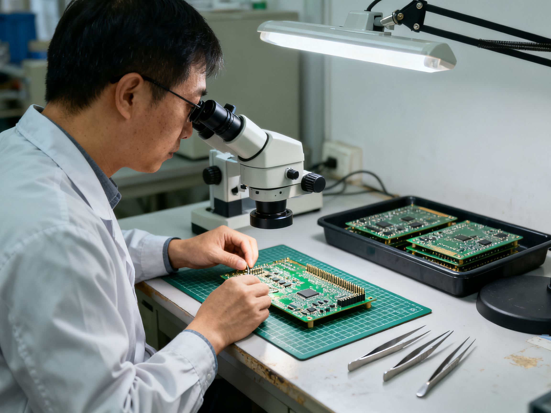
Process monitoring should include actual board-level temperature profiles, oxygen measurements, gas-flow readings, and alarm records. Where process capability matters, use these measurements to establish control limits rather than relying on visual inspection alone.
Expert Tip: Run a side-by-side trial with the same paste, stencil, components, profile, and operators. Change only the atmosphere. Otherwise, it becomes difficult to determine whether an improvement came from nitrogen or from a change elsewhere in the process.
Nitrogen Reflow in Practical Terms
Nitrogen reflow improves a solder joint by controlling one specific variable: oxygen exposure while the solder is liquid. Less oxidation allows flux to do its job more effectively, molten solder to wet the intended surfaces, and the finished joint to form more consistently.
The benefit is greatest where fine geometry, high-volume production, expensive components, or demanding quality requirements make small improvements in joint formation meaningful. Whether the investment is justified should be determined through process trials and defect-cost analysis, not by the appearance of the equipment alone.
That is the mechanism. The next question is practical: how much oxygen control does a particular operation actually need?## How Nitrogen Reflow Soldering Works: The Process Step by Step
Here is the honest version of the cycle. Five stages run in order, and nitrogen is present during all of them. But the amount of help it gives you changes from stage to stage.
Step 1: Chamber purge and seal
Before any board enters, the oven chamber is sealed and nitrogen is injected at the inlet. Fresh gas pushes air out until the oxygen reading at the board reaches your target, usually 1,000 ppm or below for lead-free work.
This takes time. The first several minutes of every morning, and after every door opening, go to conditioning the gas, not to soldering. Operators have to know that, or they will wonder where the line throughput went. IPC’s nitrogen joint-quality study treated 2,000 ppm as the level where measurable improvement appeared, and industry testing found benefits at 1,000 ppm and below.
Step 2: Preheat
The board ramps up slowly, usually 1 to 2.5 °C per second, toward 150 to 180 °C. The goal is to drive moisture out gently and reduce thermal shock on the package.
Nitrogen here does useful but modest work. It helps move moisture vapor out of the board and keeps early oxidation from starting on the components.
Step 3: Soak and flux activation
The board sits above the solder melting point for roughly 30 to 90 seconds. Flux activates and cleans the pads and terminations.
Nitrogen protects the activated flux from premature oxidation or depletion. Without it, some flux chemistry burns off too early and the joint has less cleaning power later.
Step 4: Reflow at liquidus
This is the peak, usually 245 to 260 °C for lead-free alloys such as SAC305. The solder melts, spreads, and forms the joint.
Here nitrogen does the most work of any zone. It stops new oxide films from forming on the molten solder and on the pad surfaces. Cleaner surfaces mean better wetting, less pullback, and fewer non-wetting defects on BGA and QFN terminations.
Step 5: Cooling
Nitrogen-assisted or forced air cooling freezes the joint structure. Fast, even cooling limits segregation and keeps the microstructure predictable.
Cooling matters, but nitrogen only helps indirectly here. It keeps the surface chemistry stable, so the joint freezes the way the profile intended.
From Our Experience: On a customer line running a 10-zone lead-free profile, the oxygen reading in the middle of the cycle is the number we watch. When a seal ages and oxygen creeps from 900 ppm to 2,800 ppm, the joints come out dull and the QFN feet look dry. Fixing the leak changes more than the appearance; the same board, same paste, same profile suddenly passes inspection. One real penalty to budget for: nitrogen setups often add 10 to 25 percent to soak and cooling time, and that has to land in your takt time plan.
What nitrogen does and does not do, zone by zone
| Zone | What nitrogen does well | What nitrogen barely affects |
|—|—|—|
| Purge and seal | Establishes the low-oxygen baseline | Board temperature |
| Preheat | Mild oxidation protection, cleaner moisture removal | Ramp rate and thermal shock |
| Soak | Protects flux from burning off early | Time to activate flux |
| Liquidus | Strongest effect, better wetting, less dross | Pad coverage set by stencil and paste volume |
| Cooling | Keeps surface chemistry stable through solidification | Final cooling rate |
Watch a nitrogen profile run with an oxygen readout on screen in our nitrogen usage walkthrough for reflow ovens.
The short version
Nitrogen reflow soldering works because oxygen is removed at the moment it does the most damage, while the solder is liquid. The gas itself does not heat, melt, or cool anything. It simply stops the chemistry from getting in the way.
Next up, we look at the equipment side, and where the money actually goes.## Equipment Requirements for a Nitrogen-Enabled Reflow Oven
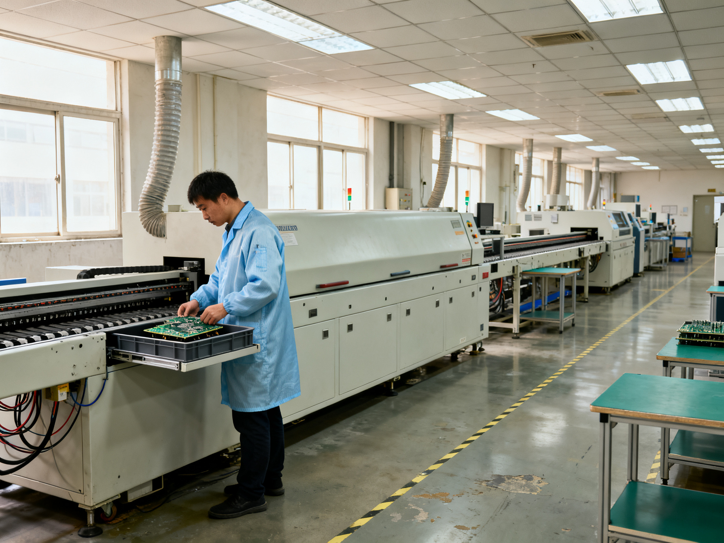
Buying a nitrogen reflow oven is mostly about the parts nobody puts on the brochure photo. Sure, the heating zones matter. But the difference between an oven that holds 500 ppm at the board and one that reads 500 ppm on the screen and sits at 3,000 ppm on the shelf comes down to sealing, flow control, and where you put the sensor.
Here is the checklist we walk customers through.
Hardware you cannot skip
| Requirement | Why it matters | What to specify |
|—|—|—|
| Sealed chamber, leak-tight doors and gaskets | A leaky chamber never reaches target oxygen, no matter how good the gas supply is | Leak test procedure, gasket service interval, door seal pressure |
| Nitrogen inlet plus controlled exhaust flow | Purging without venting lets air back in during ramp and cool | Flow ranges in Nm³/h, exhaust balance, overpressure relief |
| Dedicated sealed cooling path | Cooling air drawn from the room carries humidity and oxygen back onto the board | Separate cooling loop, sealed from process chamber |
| Oxygen sensor with live readout and alarm | You cannot control what you cannot see | Sensor range down to 0 ppm, calibration interval, alarm setpoint |
| Gas pressure and flow monitoring | Loss of gas mid-cycle means the board reflows in air, silently | Pressure switches, flow meter, safe-shutdown interlock |
| Interlocks on gas loss or excess O₂ | Protects both the product and the people | PLC-level interlock, door lock during cycle |
Where the nitrogen comes from
Bulk liquid nitrogen and piped bulk N2 are the usual choices for high-volume lines. Purity runs from 99.9% up to 99.999%, and cost per Nm³ moves with purity and delivery distance. An on-site generator makes sense when power is cheap and consumption is steady. Forming gas, a nitrogen and hydrogen blend, adds reducing power but brings hydrogen handling into your risk review. Whatever you pick, put the purity contract and delivery lead time in writing. Gas supply and consumption guidance for reflow ovens covers the sizing math most people get wrong on day one.
Profile capability and line integration
Nitrogen adds thermal mass and a heavier cooling load. Confirm the zone count, heating and cooling capacity, and whether the chamber holds a stable profile with the door sealed at your real production throughput, not on a single slow board. Also plan the integration: PLC or HMI hooks for O₂ monitoring, MES traceability points, interlock wiring, and the utility demands for compressed air, exhaust venting, and floor load.
Pro Insight: We helped a mid-size EMS customer compare retrofitting their existing oven against a new nitrogen build. The retrofit cost less, but it capped them at 8 zones and could not hold a stable profile under nitrogen once the cooling load rose. The new build cost roughly 2.5 times more and paid for itself in about 18 months because the defect rate dropped. The lesson: audit the thermal capacity before you price the gas hardware.
The procurement lens
Capital cost is the number everyone quotes. Ask the supplier for nitrogen consumption per board, energy delta at load, and consumable and maintenance costs, then work out the cost per good board. For high-volume lines, published manufacturer data shows the kind of defect reduction that makes this math work, with one production evaluation reporting a 56% drop in total defects after nitrogen was added.
If you want a second opinion on chamber design and O₂ sensor placement, this overview of nitrogen reflow oven setup is a useful sanity check to compare against vendor proposals.## Can the Process Actually Hold the Atmosphere?
Nitrogen does not create reliability by itself. The benefit depends on maintaining a low oxygen concentration throughout the useful portion of the reflow profile. If the chamber leaks, the flow rate is too low, or the doors open for too long, the line may pay the nitrogen premium without receiving the metallurgical benefit.
That makes atmosphere control an engineering discipline rather than a utility connection.
Set a target oxygen level
A conventional atmosphere reflow oven does not usually require the same purity as a semiconductor or specialty inert-gas process. The practical target should be based on the board mix, solder chemistry, package geometry, and qualification requirements. For many mixed-production electronics lines, an oxygen level in the low hundreds of ppm is operationally more useful than an extreme purity specification.
The target is not the only number to manage. Equally important are:
- Oxygen stability before, during, and after the liquidus interval
- Dew point and moisture control
- Nitrogen flow sufficient to remove volatile solder and flux products
- Chamber pressure sufficient to limit ingress when doors or panels are opened
- Recovery time after a line stop or access event
Do not treat a single oxygen reading taken at the chamber exhaust as proof that the atmosphere was controlled at the board level. Air can enter through leaks, work-piece openings, conveyor seals, cooling tunnels, or poorly sealed process-control fixtures. A useful control system samples the chamber and verifies recovery under realistic production conditions.
Design for the weakest boundary
The first step in diagnosing an installation is to identify every credible path for outside air to enter. Common sources include:
| Ingress path | Typical symptom | Corrective focus |
|—|—|—|
| Door seals and conveyor openings | Oxygen rises during production | Replace seals and verify interlocks |
| Insulation-panel joints | Localized high readings | Repair or reseal panels |
| Exhaust and ventilation balance | Pressure drifts with oven loading | Rebalance the room and exhaust system |
| Process-control and gas panels | Small but persistent leakage | Perform pressure-decay and tracer testing |
| Unsealed fixtures or covered products | Local oxygen gradients | Evaluate fixture sealing without obstructing airflow |
| Loading buffers and tunnels | Atmosphere lost before reflow | Shorten dwell time or add buffering |
Pressure testing is useful, but it must reflect how the chamber is operated. A pressure-decay test can find a large leak, while tracer-gas testing can reveal smaller leaks and poorly mixed regions. If the oven operates with negative pressure, small openings can continuously pull room air into the process. If it operates with slight positive pressure, uncontrolled leakage can still create local air paths.
Flow is not the same as purification
Nitrogen flow has several jobs. It establishes the protective atmosphere, displaces oxygen, carries away volatile products, and helps remove moisture and flux residues. Increasing flow cannot reliably compensate for a large leak. At some point, excessive flow raises operating cost, increases turbulence, and can accelerate temperature instability or disturb the intended profile.
The appropriate flow is therefore determined at production load with all doors, tunnels, and fixtures in their normal configuration. Measure:
- Oxygen at the chamber inlet and outlet
- Oxygen during heating, liquidus, cooling, and hold
- Recovery time after simulated door openings
- Pressure at operating, standby, and idle states
- Nitrogen consumption per board at different throughputs
- Temperature uniformity and profile stability under the same conditions
This baseline makes the installation auditable. Without it, an equipment supplier can claim that the chamber is nitrogen-enabled without demonstrating that the atmosphere remained within the process target at the board.
Manage moisture as a separate variable
Nitrogen lowers the oxygen available for oxidation, but it does not automatically dry the chamber or the line. Ambient humidity, wet paste, hydrated materials, and moisture retained in packaging can still create solder balls, poor wetting, or residue.
A dew-point target should be established independently from the oxygen target. Confirm that the gas source and delivery system can deliver the required moisture level. Then monitor actual conditions rather than relying only on generator specifications. If a membrane-based generator cannot meet the required dew point during peak demand, the line may need a dryer, additional gas storage, or a larger generation capacity.
The same discipline applies to paste handling. Reflow atmosphere control cannot compensate for material that enters the oven with excessive moisture or contamination.
Verify the profile and atmosphere together
Nitrogen affects heat transfer and the oven environment. A process that works in air may need profile adjustments after conversion because the exhaust load, gas-flow pattern, component thermal mass, and chamber configuration have changed. Profile changes should be based on measured board temperatures, not inferred from a component recipe or copied from an empty test coupon.
Use representative boards and include:
- Minimum and maximum package temperatures
- Time above liquidus
- Ramp profile for sensitive components
- Dwell or soak time, if applicable
- Cooling rate
- Oxygen level during the critical reflow interval
- Rework rate and defect Pareto before and after conversion
The most credible evidence will connect three layers: the measured atmosphere, the measured thermal profile, and the measured product outcome. A low oxygen number without a stable profile is incomplete, just as an acceptable profile without atmosphere data is insufficient.
Commission the installation deliberately
A useful commissioning plan has five stages:
1. Establish the baseline
Run the line in its current configuration and record defects, rework, scrap, gas use, energy use, and cycle time. Use enough production volume to establish a meaningful baseline rather than relying on a short internal trial.
2. Test leakage and pressure behavior
Inspect seals, repair penetrations, verify door and conveyor interlocks, and document how chamber pressure changes with the oven hot and under production load.
3. Map the oxygen profile
Measure oxygen during start-up, steady production, planned pauses, recovery after door opening, and overnight conditions. Locate persistent high-oxygen zones and determine whether they are associated with leaks, airflow patterns, or operating practices.
4. Qualify representative product
Run the complete product mix through the sealed process. Compare thermal profiles, first-pass yield, defect types, rework, and line balance against the baseline. Keep packaging and component substitutions visible because any of them can change the result.
5. Train and audit
Operators need clear rules for door openings, pauses, gas alarms, purge sequences, and maintenance. A short, specific instruction is more valuable than a generic safety briefing. Add oxygen and pressure checks to routine line audits, and record the readings with each production lot or maintenance event.
Failure modes that deserve attention
The most common atmosphere-control problems are not exotic. They are ordinary operating failures:
- A door seal has compressed or been damaged
- An interlock has been bypassed for cycle-time convenience
- A loading buffer remains open longer than planned
- The gas supply runs at a lower pressure than specified
- A generator is operating at the edge of its capacity
- The oxygen sensor has drifted or is installed in an unrepresentative location
- Operators interpret an alarm without recording the event
- Maintenance restores a panel incorrectly after a service call
These issues can remain invisible when the primary metric is first-pass yield because yield is noisy, production mixes change, and rework is sometimes underreported. Preventive controls are more effective when they are based on oxygen, pressure, dew point, and event-response time.
A practical acceptance test
Before considering the installation complete, define pass or fail criteria for the real operating state. For example:
| Parameter | Suggested evidence |
|—|—|
| Oxygen during liquidus | Within the agreed process target at representative locations |
| Atmosphere recovery | Back within target within the validated interval after a door cycle |
| Dew point | Within specification at production load |
| Leak integrity | No unresolved major leak; small leaks addressed through trend data |
| Gas consumption | Stable and explained per unit of throughput |
| Thermal profile | Meets product-specific process limits |
| Product outcome | No adverse change in defects, rework, or stress indicators |
| Alarm response | Recorded, with no unlogged bypass or unresolved excursion |
The exact limits should come from process engineering, customer requirements, and the capability of the equipment. The important point is to establish them before the business case is finalized.
The economic question is operational
Nitrogen can be economically attractive when it prevents rework and reduces waste, but those savings depend on stable control. If the chamber repeatedly loses atmosphere, the plant pays for nitrogen twice: once for the gas itself and again for defects the installation was supposed to prevent.
That is why the purchasing decision should include the cost of monitoring, maintenance, sensor calibration, seal replacement, training, and qualification. These costs are not incidental overhead. They are part of the process.
A good installation also makes the economic case easier to defend because every operating hour can be reconciled to gas consumption, board throughput, and recorded process conditions. Instead of relying on a broad claim that nitrogen improves yield, management can see whether the atmosphere remained in control and whether the line improved for the expected reasons.
Bottom Line
Nitrogen-assisted reflow can reduce oxidation-related defects, improve wetting consistency, and lower rework and material waste, particularly on fine-pitch, mixed-technology, and high-reliability assemblies. The evidence is strongest for the direction of the effect and weaker for universal numerical claims, so every line should validate the result against its own products and defect Pareto.
The equipment is only half the project. The decisive controls are measurement, sealing, flow design, moisture management, disciplined operation, and maintenance. Specify those controls before installation, qualify the system with representative product, and audit the process afterward.
The best business case is not the one with the lowest quoted nitrogen price. It is the one in which the atmosphere is stable, the thermal profile is understood, the defects move in the expected direction, and the savings remain visible in the line ledger.## Nitrogen in Wave Soldering and Selective Soldering: Where It Fits on the Line
Nitrogen is not a one-process trick. It shows up in three different places on a modern SMT line, and each one asks for a different equipment setup.
Reflow handles surface mount boards. Wave soldering handles through-hole and mixed-technology assemblies. Selective soldering covers the odd heavy components that nobody wants to wave solder.
Where nitrogen does the work
Wave soldering. Nitrogen blown across the solder pot creates a protective layer over the molten solder. That cuts dross formation and, more usefully, kills the oxide skin that turns a clean wave into a ball of grey scum. On high-volume THT lines running lead-free, that skinned solder is what drives poor wetting and cold joints.
Selective soldering. Nitrogen shielding around the nozzle protects the molten solder column from the moment it leaves the tip. This is where it matters most for heavy through-hole connectors, power modules, and ground lugs in military, automotive, and industrial equipment.
Reflow. Chamber-wide atmosphere control, as covered above.
Quick comparison
| Process | Board type | Nitrogen application | Typical defects addressed |
|—|—|—|—|
| Reflow | Surface mount (BGA, QFN, 0402) | Sealed chamber atmosphere | Non-wetting, dull joints, dross, oxidation |
| Wave soldering | Through-hole, mixed | Nitrogen blanket over the pot | Skinned solder, cold joints, poor wetting on THT |
| Selective soldering | Heavy THT, power parts, connectors | Nozzle shielding at the tip | Oxidation during dwell, weak wetting on large pins |
Putting them together
Mixed-technology lines are where the combination pays off. A line with a nitrogen-enabled reflow oven, a nitrogen-assisted wave machine, and a selective solderer covers SMT, THT, and rework under one process window. At S&M Co. Ltd., we build exactly that combination, so the gas controls, interlocks, and MES hooks are specified together instead of patched in later.
If your mix is mostly SMT, start with the reflow chamber. If connectors and power parts dominate, the selective solderer pays first. Curious about the gas math on your line? Send us your board mix and cycle time and we will size it with you.
Next up, we look at what the numbers actually cost.