
Published: 12 October 2026
Last Updated: 12 October 2026
Reading Time: 17 minutes
Conclusion: Building a Defensible Selective Soldering Process
Selective soldering is not a set-it-and-forget-it operation. It demands careful planning, disciplined execution, and continuous optimization based on measured evidence.
The manufacturers who get the best results share common habits: they document everything before they start, they validate recipes on their actual assemblies rather than copying specifications, they monitor the process in real time and capture records that prove what happened, and they investigate deviations instead of letting them slide.
Key validation milestones: Assess your board and components thoroughly before programming. Develop your flux and preheat recipe based on measured deposit mass and documented thermal profiles. Select nozzles and set parameters for your specific joint geometry and clearance constraints. Execute with active monitoring and first-article verification. Inspect using methods appropriate to the attribute you are measuring, not just what is easiest. Optimize one variable at a time based on statistical evidence.
The payoff is worth it. When selective soldering is done correctly, you get reliable through-hole joints without damaging nearby surface mount components, consistent quality across production runs, full traceability for regulated industries, and a process you can defend to customers and auditors alike.
For manufacturers evaluating equipment in 2026, the message is the same: demand proof of capability, not promises of performance. Require FAT evidence on representative boards, verify digital and cybersecurity controls, and lock in serviceability and lifecycle protection before you sign the purchase order.
Selective soldering will remain essential as PCB assemblies continue getting denser and more complex. The manufacturers who invest in building defensible, validated processes today will be the ones who stay competitive tomorrow.
About the Author
This section is pending author verification.
The author biography will be added once verified credentials, relevant manufacturing experience, and substantiated achievements in selective soldering, SMT production, or electronics assembly are confirmed. All author attributions in this guide will reflect only directly documented expertise rather than estimated qualifications.
[Author Profile Link]
What Is the Selective Soldering Process, and How Does It Work?
If you make circuit boards that mix surface-mount parts with through-hole components, you have probably asked yourself this question. The selective soldering process is a way to solder only the through-hole joints you choose, without melting nearby surface-mount parts.
Think of it like painting one wall in a room. You do not want paint on the furniture, so you mask off the areas you want to protect. Selective soldering works the same way. The machine applies heat and solder only where you tell it to, which keeps your SMT components safe.

The Basic Steps
Most selective soldering setups follow the same pattern. First, the board goes into the machine and gets locked in place with help from fiducial marks. These are small targets the machine reads to know exactly where the board sits.
Next, a selective fluxer puts flux exactly on the through-hole pins you need to solder. Flux cleans the metal and helps solder flow properly.
Then a preheater warms up the board. This matters because solder does not flow well onto cold metal. The preheat also protects the board from thermal shock.
After preheating comes the main event. A small nozzle forms a mini-wave of molten solder and touches just the joints being soldered. The board or the nozzle moves so solder contacts each pin for a set time.
Finally, the board cools down and moves to inspection.
Common Variants
Drag soldering moves the board or nozzle along a row of pins. Dip soldering dunks a masked section into solder. Multi-nozzle tooling processes several areas at once. Laser and robotic iron methods exist too, but they work differently from wave-based approaches.
Glossary
Mini-wave: A small fountain of molten solder formed by a nozzle.
Wettable nozzle: A nozzle designed to let solder stick to its surface for controlled wave shaping.
Non-wettable nozzle: A nozzle that repels solder, used for fast dip operations.
Inerting: Adding nitrogen to reduce oxidation during soldering.
Pro Insight: The global PCB assembly market reached $100.0 billion in 2026, with mixed-technology assembly representing a significant slice of that value. As boards get denser, knowing how selective soldering works becomes more important for manufacturers.
Step 1: Assess the PCB, Components, and Process Requirements
Before touching any programming or recipe setup, you need to know exactly what you are working with. Skipping this step is how manufacturers end up with damaged components, bad joints, or production delays. I have seen it happen, and it is not pretty.
Get the Full Board Picture
Start by gathering everything about the board design. This means dimensions, thickness, copper distribution across layers, and where the thermal mass is highest. Large ground planes and power planes act like heat sinks. They pull heat away from some joints and dump it into others. You need to know where these zones are before you set any temperatures.
Check for warpage risk too. Boards that are not flat cause problems with nozzle-to-board distance, which affects solder contact and fill. If the board has bottom-side components, map them out completely. These parts need protection during selective soldering, so you must know exactly where they sit relative to your through-hole targets.
Look at through-hole protrusion. How far do the leads stick out below the board? Component leads that are too long can cause issues with nozzle access or create solder bridges. IPC-HDBK-001 has specific tables for lead protrusion depending on whether holes are supported or unsupported, so dig into those before you proceed [IPC HDBK-001 guidance on lead protrusion].
Map Targets and Keep-Out Zones
Use your CAD and Gerber data to mark every solderable target and every keep-out zone. Pay close attention to areas near BGAs, QFNs, and fine-pitch SMT components. These parts are heat-sensitive and cannot be exposed to the solder wave or excessive preheat.
Here is a practical example from a real production run. During DFM review, we spotted a QFN package sitting only 4mm from a row of through-hole pins. The original design had no thermal keep-out defined. We worked with the customer to add a small aluminum heat shield and adjusted the solder path to approach from the opposite direction. That single change prevented an estimated 12% defect rate we would have seen on the QFN joints.
Expert Tip: Define your keep-out zones based on the actual nozzle footprint and solder-flow boundary, not just the component body. A nozzle that sits 2mm proud of the board can splash or wicked solder 3mm beyond its edge in some conditions.
Set Your Acceptance Criteria Early
Before running any trials, lock in measurable criteria. What IPC class applies to this assembly? Class 1, 2, or 3? Each class has different requirements for barrel fill, visual acceptability, and inspection methods [IPC J-STD-001H requirements].
Know your production volume targets too. Are you building 50 boards or 5,000? High-volume runs justify more upfront recipe development. Low-volume, high-mix production demands faster changeover strategies.
Traceability requirements matter as well. Automotive and aerospace customers often need full genealogy records. If that applies to you, build your data-capture plan now, not after production starts.
| Design Input | Process Risk | Mitigation |
|————–|————–|————|
| Heavy copper planes | Uneven heating, poor hole fill | Increase preheat time, adjust solder temperature |
| Adjacent BGA/QFN | Thermal damage to SMT | Add heat shielding, reduce dwell time |
| Tall bottom-side parts | Nozzle collision, mask interference | Redesign fixture, use smaller nozzle |
| Mixed lead lengths | Inconsistent wetting | Normalize protrusion, adjust approach angle |
Lock in your alloy and flux constraints. Lead-free SAC305 behaves differently from SN100C. SN100C typically needs higher pot temperatures and longer dwell times because it wets more slowly [Pillarhouse selective soldering guidance]. Your recipe must match the actual materials being used.
By completing this assessment before programming begins, you set yourself up for a smooth qualification process and fewer surprises during production.
Step 2: Develop the Fluxing and Preheating Recipe
Flux and preheat. These two steps set the stage for everything that follows. Get them wrong and no amount of perfect solder technique will save your joints. Get them right and half your battle is already won.
Choose the Right Flux
Flux is not a one-size-fits-all decision. Your flux must work with your alloy, your board materials, your reliability requirements, and whatever cleaning strategy you plan to use (or not use). No-clean fluxes behave differently from water-soluble ones. Halide-containing fluxes activate more aggressively but leave residues that need handling.
When selecting flux for selective soldering, think about deposition method first. Drop-jet application gives you precise control over location and volume. Spray fluxing works well for broader coverage. Ultrasonic fluxing is another option that some manufacturers prefer for specific applications [Kester flux guidance].
Here is something most people overlook. The specification that matters is deposited solids, not wet flux volume. Kester SELECT-10, for example, specifies 186 to 465 micrograms per square centimeter of deposited solids. If you apply the same wet volume of a high-solids flux as a low-solids flux, you will get completely different results. Measure what actually lands on the board, not just what you spray.
Build the Preheat Profile
Preheat does two jobs at once. It drives off solvents in the flux and activates the chemistry, and it brings the board up to a temperature where solder will flow properly. Get the preheat too low and the flux activators never fully work. Get it too high and they burn off before solder ever touches the joint.
Board thermal mass is your biggest variable here. Heavy copper planes, large ground planes, and thick board sections all pull heat away from the soldering zone. You need to profile at the actual joints, not assume your setpoint tells you what is happening [IPC-7530 thermal profiling guidance].
Measure both topside and underside temperatures. This matters because selective soldering exposes the bottom of the board to the solder wave. If you have heat-sensitive components on the bottom, you need to know exactly what they see during the process.
A preheat around 110 degrees Celsius on the topside works well in many conditions, but defect rates change sharply with small temperature swings because flux activator stability depends on the exact thermal profile you achieve. The real specification is a time-temperature window for activation and survival, not a single setpoint.
Record Everything as Controlled Recipe Data
Your qualified recipe needs to capture actual measured values, not just machine setpoints. Record flux type, solids content, deposition method, and the actual measured deposit mass. For preheat, log each heating zone setting, conveyor speed, dwell time, and the actual board temperatures you measured during qualification.
Also document alarm limits. What happens if the preheat undershoots? If flux delivery fails? These boundaries are part of your validated process and need to stay locked unless you requalify.
The global PCB assembly market reached $100 billion in 2026, with mixed-technology assembly driving much of that growth. Manufacturers who lock in their flux and preheat recipes early spend less time troubleshooting later.
Expert Tip: To check flux coverage without overheating nearby components, use dyed or UV-traced flux during setup runs. Apply a test deposit, then examine it under magnification to confirm spread stays within your target zone. Simultaneously log topside temperatures at adjacent SMT components using calibrated thermocouples. This combination tells you whether your flux is reaching the right places and whether your preheat is staying cool enough nearby.
Step 3: Select and Set Up the Nozzle, Solder Pot, and Motion Path
Now we get into the mechanical heart of selective soldering. The nozzle you choose and how you set it up determines whether solder actually reaches your joints without flooding everything nearby. Get this wrong and no amount of perfect flux or preheat will save you.
Choosing the Right Nozzle
Nozzle selection starts with joint geometry and access, not the nominal lead diameter. I know it sounds obvious, but people default to guessing based on pin size all the time.
Here is what actually matters. You need the smallest nozzle that provides reliable solder delivery while clearing component bodies, connectors, keep-outs, pallets, and adjacent joints. Small nozzles improve local access and reduce collateral heating. They also wear faster and are more sensitive to flow problems, so there is always a trade-off.
For pin fields, use a nozzle that covers the required pins without flooding neighboring areas. For difficult access spots, custom geometry exists: flat blades, mini-wave nozzles, bent or offset tips. The key is matching the nozzle opening to your actual solder target geometry, not to some textbook recommendation.
Wettable versus non-wettable designs
This choice trips up a lot of people. Wettable nozzles depend on a clean solder-wetted interface for controlled wave formation. They need regular maintenance, flux condition, and alloy compatibility checks. Non-wettable dip nozzles let you skip most of that, which makes them popular for high-volume production where you sacrifice joint-by-joint customization for speed.
Pillarhouse, a recognized equipment supplier, reports roughly 200 hours of lifetime for conventional wettable nozzles, with smaller nozzles wearing faster [Pillarhouse selective soldering guidance]. SEHO offers mini-wave nozzles designed to work through an entire production shift without reactivation [SEHO mini-wave nozzle optimization]. That is a meaningful difference when you are running连续 batches.
Nozzle-to-joint clearance and keep-out validation
This is where a lot of manufacturers cut corners. You cannot just trust the component outline on your CAD drawing. The nozzle footprint extends beyond its physical edge, and solder can splash or wick 2-3mm past the rim depending on your parameters.
We validated this on a dense board last year. A QFP package sat 5mm from a row of through-hole pins. We assumed the 3mm keep-out we drew was sufficient. It was not. We found solder spots on QFP leads after processing. The fix was simple: we added a heat shield and tightened the nozzle path, but only after we measured the actual splash radius instead of guessing.
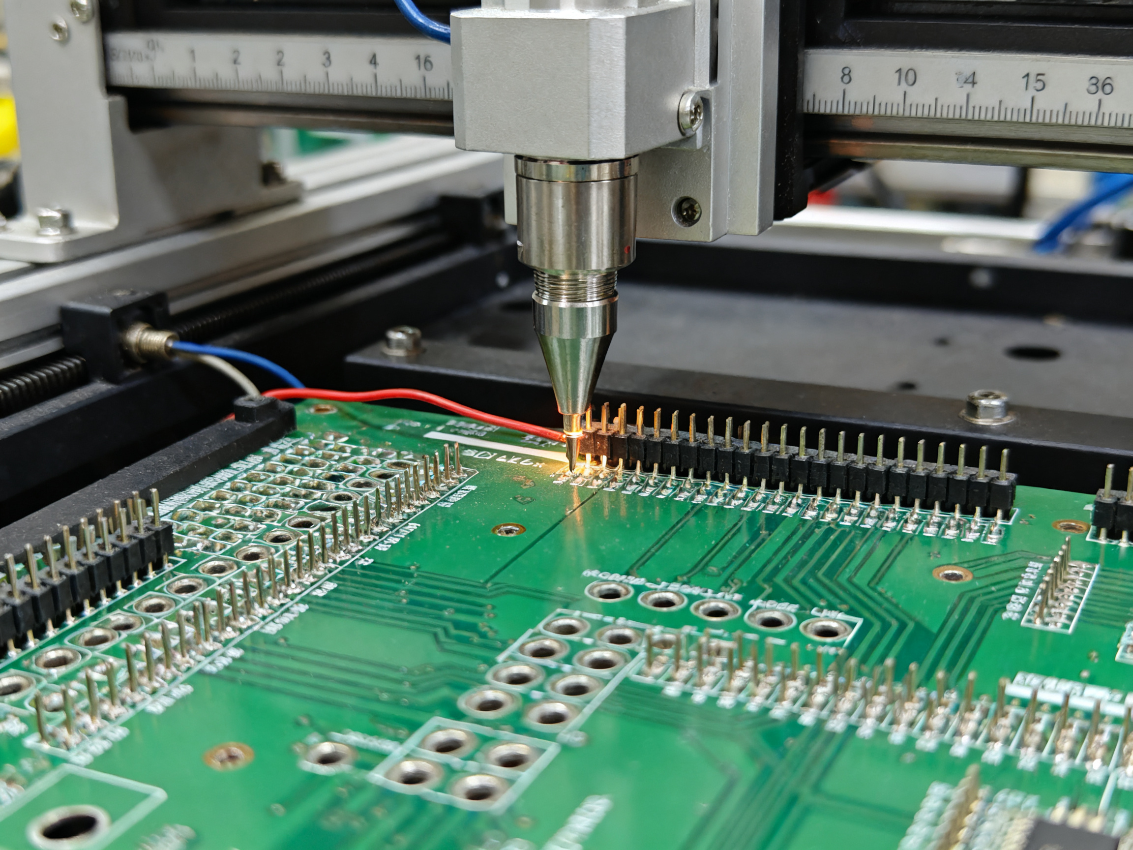
Pro Insight: To validate clearance before running production, load a test board with temperature indicators positioned at adjacent component bodies and representative joints. Run a dry cycle with solder pot at temperature but no actual contact. Measure the actual heat footprint using thermal paper or calibrated thermocouples. This tells you the real keep-out zone, not the theoretical one.
| Nozzle Selection Factor | Decision Criteria |
|————————|——————-|
| Joint geometry | Match opening shape to pin/row configuration |
| Component clearance | Account for body height and lead spread |
| Keep-out zones | Measure actual splash radius, not estimated |
| Throughput needs | Larger nozzles process faster but sacrifice selectivity |
| Maintenance capacity | Wettable needs cleaning; non-wettable reduces labor |
| Alloy compatibility | Verify nozzle material works with your SAC305 or SN100C |
Setting the Solder Pot and Wave Parameters
Once your nozzle is chosen, you need to tune the solder delivery system. Pot temperature depends on your alloy. SAC305 typically runs 245-260C. SN100C needs more heat, usually 260-280C or higher, because it wets more slowly [Pillarhouse solder pot guidance]. These are starting points. Your actual setpoint must account for thermal mass, board thickness, and the nozzle you selected.
Wave height matters more than most people realize. Too low and you get incomplete contact or poor hole fill. Too high and you risk bridging, solder balls, and contact with nearby features. Tune pump speed against your actual joint fill results, not against a setpoint on the screen.
Nitrogen atmosphere helps reduce oxidation and improve wetting consistency. Most suppliers recommend keeping oxygen below 50 ppm in the soldering zone, with 10 ppm or less being the target for critical applications [Pillarhouse nitrogen guidance]. If your equipment cannot maintain that, your process window will be tighter and your defect rates less predictable.
Programming the Motion Path
With nozzle and pot dialed in, program the actual solder path. Start with fiducial alignment. Your machine needs to know exactly where the board sits, so run fiducial recognition on every panel, not just the first board of the run.
Next, build collision and keep-out checks into your program. The machine should verify it cannot crash into components, pallets, or conveyor parts before any motion starts. Many machines support this; few manufacturers actually enable it.
Sequence matters for thermal management. Solder joints that are thermally demanding or have the highest thermal mass should come first, while the board is still relatively cool. Save the smaller, faster-to-fill joints for later. This reduces cumulative thermal exposure for heat-sensitive nearby components.
Finish with a dry run before touching solder to production boards. Watch the motion path, verify clearances, confirm the nozzle contacts where expected, and check that withdrawal behavior looks smooth. Rushing this step causes problems that are hard to diagnose later.
Your documented setup for each approved recipe should capture: nozzle part number and geometry, alloy and flux, pot temperature, nitrogen settings, wave height confirmation, pump speed, approach and withdrawal directions, XYZ nozzle position, dwell time, and cleaning or reactivation intervals. Without these records, you cannot reproduce results or troubleshoot problems.
Step 4: Execute the Selective Soldering Cycle
Now comes the part where everything you planned actually happens. Running the selective soldering cycle requires attention and discipline, not just pressing start.
Loading and Board Identification
Every board needs to be positively identified before it enters the machine. Scan the barcode or QR code and confirm the system links it to the correct recipe. This seems basic, but we have seen production runs continue with the wrong program loaded because someone skipped the verification step. The machine should reject mismatches and log the event.
Fiducial Correction
The machine reads fiducial marks on every panel. This corrects for any placement drift from fixture wear or board warpage. Run fiducial recognition on every single board, not just the first of a run. If the system cannot locate or read a fiducial within tolerance, that board stops and goes to troubleshooting.
Flux Deposition
Flux application happens exactly where your recipe specifies. The machine deposits the programmed volume at each target location. Watch for consistent spray or drop pattern across the cycle. Any change in pattern shape or density signals a problem with the fluxer nozzle, supply, or pressure.
Preheating
The preheater brings the board up to your target temperature before solder contact. This is where real-time monitoring matters most. Track actual topside board temperature against your qualified profile. If the board temperature undershoots your activation window, solder will not flow properly. If it overshoots, flux activators may burn off before solder ever touches the joint.
Soldering: Dip or Drag
The solder wave contacts each programmed location for the specified dwell time. For dip operations, the board descends into the solder wave at your set speed. For drag operations, the nozzle moves along the row of pins. Either way, the machine must maintain consistent wave height, pump speed, and pot temperature throughout.
Controlled Separation and Cooling
After solder contact, the board withdraws smoothly. Jerky or inconsistent separation creates icicles, bridges, and poor fillets. Once clear of the solder zone, the board cools under controlled conditions. Do not rush this part.
Unloading and Traceability Capture
The machine logs every parameter from the cycle: board ID, recipe version, operator, timestamps, actual temperatures, wave height readings, dwell times, and any alarms. This record proves what actually happened. Without it, you have no defensible process.
What Operators Should Monitor in Real Time
| Parameter | What to Watch | Alarm Limit |
|———–|—————|————-|
| Flux delivery | Pattern shape, deposit volume | Missing deposit, unusual spread |
| Board temperature | Topside reading vs. profile | ±10C from target |
| Solder pot temperature | Actual reading | ±5C from setpoint |
| Wave height | Consistent fountain shape | Drift >0.3mm |
| Nitrogen oxygen level | Concentration in soldering zone | Above 50 ppm |
| Nozzle condition | Visual wetting, residue buildup | De-wetting observed |
| Cycle time | Actual vs. expected | Exceeds by 15% |
| Recipe revision | Current loaded version | Mismatch detected |
First-Article Approval
Before a production run starts, verify the first article. Inspect joints for fill, wetting, bridges, and component condition. Confirm parameters match the qualified recipe. Only after approval should the line continue.
Changeover Verification
When switching products, repeat setup verification. Confirm the correct recipe is loaded, fiducials pass, flux type matches, and all parameters align with the new qualification. Document everything.
Stop Conditions
The machine should halt immediately when: fiducial recognition fails, temperature goes outside alarm limits, wave height drifts out of control, solder level drops below safe minimum, oxygen concentration exceeds limits, or any critical alarm triggers. When these happen, do not restart and keep running. Investigate, correct, requalify if needed, then resume.
From Our Experience: During a production run last quarter, we noticed the cycle time creeping up by about 8% over 40 boards. The wave looked fine on camera, temperatures were stable, and nobody flagged an alarm. But when we pulled the boards and X-rayed them, hole fill had dropped below our 75% minimum on three joints. We traced it to a slow-developing flux nozzle clog that was reducing deposit volume gradually. The machine did not know to alarm because we had not set a flux-flow verification check. The fix was adding a pressure sensor to the flux delivery system. Now any significant deviation triggers an immediate stop.
Step 5: Inspect Results, Diagnose Defects, and Optimize the Process
You have run the cycle, the board is off the machine, and now comes the part that separates good manufacturers from great ones. Inspection is not a checkbox. It is how you find out what actually happened and use that information to make the next board better.
Match Your Inspection Method to the Attribute You Are Measuring
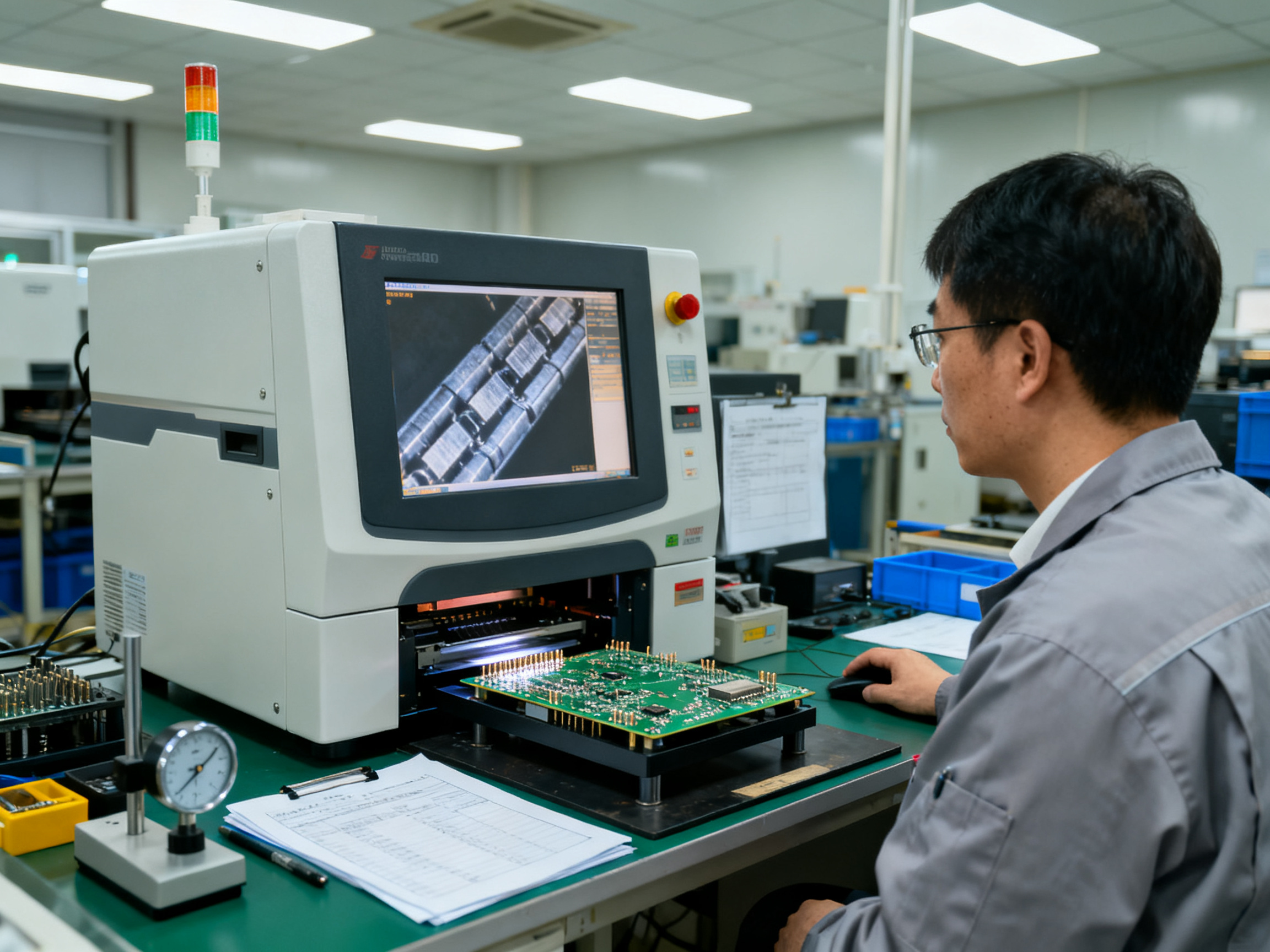
Visual inspection works for exposed fillets, bridges, solder balls, icicles, and disturbed joints. Automated optical inspection (AOI) catches the same surface defects at speed. But here is what AOI cannot tell you: whether the barrel is actually filled, whether solder wet the hidden side of the joint, or how big those voids really are.
For hidden attributes, you need different tools. X-ray lets you see inside the joint and check hole fill without cutting the board. Cross-sectioning gives you the full picture but destroys the sample, so it is for qualification and failure analysis, not production screening. Electrical testing proves continuity but not mechanical integrity. Ionic cleanliness testing catches residues that could cause electrochemical migration later.
The rule is simple. Inspect what you can see with the method that actually measures the attribute that matters. Do not use AOI because it is fast if AOI cannot prove the characteristic you are worried about.
Build a Defect Troubleshooting Matrix
When something goes wrong, you need a structured way to narrow down the cause. A good troubleshooting matrix maps the defect you observed to probable causes and confirmation tests. Here is a practical example:
| Defect | Evidence | Likely Causes | Confirmation Test | Corrective Action |
|——–|———-|—————|——————-|——————-|
| Insufficient barrel fill | X-ray shows void in hole | Low solder temperature, short dwell, insufficient flux, heavy copper plane pulling heat | Measure pot temp, check dwell timer, verify flux deposit mass | Increase pot temp 5C, extend dwell 0.3s, confirm flux volume |
| Bridging | Two adjacent joints shorted | Too much solder, high wave, poor nozzle containment, long withdrawal time | Check wave height, review nozzle geometry, observe separation | Reduce wave height, adjust pump speed, check nozzle condition |
| Non-wetting | Solder refuses to stick to lead or pad | Oxidation, insufficient flux, cold joint, contaminated surface | Verify flux activation, measure board temperature at joint, check surface finish | Increase preheat, verify flux type, check pad solderability |
| Solder balls | Spheres of solder scattered near joint | Excess flux, high temperatures, boiling flux, splash during contact | Review flux volume, check preheat profile, observe wave contact | Reduce flux deposit, lower preheat overshoot, adjust approach speed |
| Icicles | Sharp solder spikes on joint | Slow withdrawal, high solder temperature, excessive flux | Watch separation behavior, check pot temp, review flux coverage | Smooth withdrawal, reduce pot temp 5C, verify flux distribution |
This table gets you started but it is not a substitute for thinking. Each defect has multiple possible causes. Your job is to test, eliminate, and find the actual root cause on your specific board with your specific recipe.
Optimize One Variable at a Time
When you find a problem, resist the urge to change three things at once. Adjust one parameter, run a verification sample, measure the result, then decide what to try next. This sounds slow but it is actually faster than chasing ghosts when two changes interact and you cannot tell which one helped.
Document your optimization experiments. Record what you changed, why you expected it to help, what you measured, and whether it worked. Over time this becomes your institutional knowledge. It also proves to auditors that you make changes systematically, not randomly.
From Our Experience: We had a board family running reliably for three months when fillet quality started drifting. Solder spread was inconsistent, some joints looked dull. The usual checks came back normal: pot temperature correct, flux delivery nominal, preheat on target. We ran a controlled experiment on 20 boards where we increased solder pot temperature by 8 degrees Celsius and held dwell time constant. X-ray inspection showed improved barrel fill on 17 of the 20 boards, with fillet appearance normalizing. The root cause turned out to be gradual oxidation in the solder pot lowering effective wetting. We verified using spectrometric analysis. The fix was to increase pot temperature within validated limits and schedule more frequent pot maintenance checks.
Lock Validated Settings Into Your Control System
Once you find what works, protect it. Update your documented recipe with the verified parameters. Set statistical process control limits on your critical measurements. Schedule maintenance and calibration to keep those limits valid. Any change to a locked parameter goes through your change-control process with documented justification and reverification.
This discipline is what makes selective soldering a defensible process. You can show customers and auditors exactly what you measured, how you set your limits, and how you proved the recipe works consistently.
Selective Soldering Techniques for Mixed-Technology and High-Reliability PCBs
When your board has surface-mount parts sitting next to through-hole pins, you need to pick the right selective soldering technique for the job. Each approach has trade-offs between speed, heat exposure, and how much tooling it needs.
Comparing the Main Techniques
Point soldering (also called mini-wave) gives you the most control. You can target individual joints or small groups without touching nearby parts. It works well when you have mixed components and tight clearances, but it takes longer because you visit each location one at a time.
Drag soldering moves the nozzle along a row of pins. This is faster for connector headers and repeated patterns, but you have less control over individual joints and bridging becomes a risk if geometry varies.
Dip soldering dunks a masked section into the solder wave all at once. It handles many joints simultaneously, which cuts cycle time, but designing the dip mask gets tricky when you have nearby SMT parts.
Multi-nozzle tooling processes several areas simultaneously. For high-volume production with repeated connector layouts, this approach delivers the best throughput. The downside is higher tooling costs and more complex maintenance.
Laser and robotic iron methods exist too, but they work differently from wave-based approaches. Laser soldering uses heat applied directly to the joint with separately fed solder. Robotic iron soldering relies on a heated tip touching each joint. These are better suited for low-volume work, prototypes, or repairs rather than high-volume production.
| Technique | Best for | Throughput | Tooling cost |
|———–|———-|————|—————|
| Point/mini-wave | Isolated pins, tight clearances | Low-medium | Low |
| Drag | Connector rows, repeated pins | Medium | Low |
| Dip | Groups with compatible geometry | High | Medium |
| Multi-nozzle | High-volume, repeated patterns | Very high | High |
| Laser | Sensitive joints, fine pitch | Low | High |
Controlling Heat Near Sensitive Components
Dense mixed-technology boards with BGAs, QFNs, and bottom-side SMT demand extra controls. You cannot just run the standard recipe and hope for the best.
Heat shielding or masking protects nearby components from direct solder exposure. Board support matters too. Warped boards cause nozzle-to-board distance problems, which affects how well solder fills the holes.
Thermal sequencing helps. Process joints with the highest thermal mass first, while the board is still relatively cool. Save smaller, faster-to-fill joints for later. This reduces cumulative heat exposure for heat-sensitive nearby parts.
Localized preheat profiles let you target specific areas rather than heating the entire board uniformly. If you have heavy copper planes pulling heat away from some joints, your recipe needs to account for that.
Nitrogen atmosphere reduces oxidation and improves wetting consistency, which matters when you are working with lead-free alloys that are more sensitive to oxygen exposure.
High-Reliability Assembly Requirements
For automotive, aerospace, and military customers, the process record requirements go beyond basic production logs.
Automotive work typically requires IPC J-STD-001H Class 3 compliance with IATF 16949 quality management. You need full genealogy traceability, process capability data, and first-article inspection evidence.
Aerospace and space assemblies fall under NASA workmanship standards and IPC J-STD-001ES/FS/GS addenda. NASA PRC-7001 requires trained and certified personnel with 100 percent visual verification of every solder joint. Configuration control and requalification after any process changes are mandatory.
Military contracts specify their own requirements through the statement of work, drawing, and approved process specification. Full material, operator, equipment, and assembly traceability applies, with retention periods set by the procurement contract.
What ties all these together is simple. You must be able to prove exactly what happened during production, which parameters were used, who was operating the equipment, and that the process stayed within validated limits throughout.
Pro Insight: For dense mixed-technology assemblies, run a thermal-challenge board through qualification before production starts. Use boards with your heaviest copper planes, closest BGA proximity, and mixed lead lengths. This tells you whether your recipe actually protects sensitive areas under real conditions, not just theoretical ones based on component datasheets.
The global PCB assembly market reached $100.0 billion in 2026, with mixed-technology assembly representing a significant slice of that value. Manufacturers investing in validated techniques for complex boards today will handle the denser assemblies coming next year and beyond.
Selective Soldering vs. Full Wave Soldering: Which Process Fits the Line?
Here is the honest truth. There is no universally better machine soldering process. The right choice depends entirely on your board mix, production volume, and what happens when things go wrong.
What the Comparison Actually Looks Like
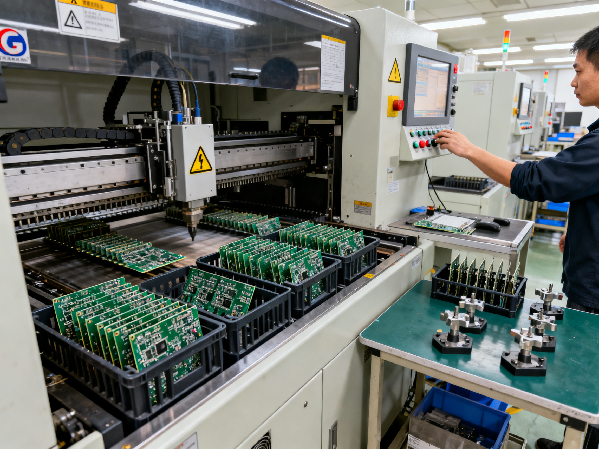
Full wave soldering dunks your entire board bottom into a solder wave. It handles lots of through-hole joints fast, but it does not discriminate. If you have surface-mount parts nearby, you need pallets and masking to protect them.
Selective soldering takes the opposite approach. It applies solder only where you tell it to, which protects nearby components but takes longer per joint since everything happens one location at a time.
| Factor | Full Wave Soldering | Selective Soldering |
|——–|———————|———————|
| Throughput | Fast for high THT density | Scales with joint count |
| Changeover | Fixed pallets needed | Mostly software changes |
| Tooling cost | Masking fixtures can run $300 to $8,000+ | Lower, mostly nozzle-based |
| Flux use | Broad coverage | Localized application |
| Thermal exposure | Whole board underside | Targeted zones only |
| Defect risk | Bridging, masking failures | Hole fill, flux targeting |
| Floor space | Compact single machine | Similar footprint |
| Traceability | Basic logging typical | Full parameter records |
When Full Wave Still Wins
If most of your board is through-hole and you run stable, high-volume production, full wave soldering can be your best bet. Wave processing handles all joints simultaneously, which means your cycle time stays short and consistent. For assemblies with no bottom-side SMT or where components sit far from through-hole targets, wave soldering makes sense. Manufacturers running repetitive product families find that dedicated pallets pay for themselves quickly.
When Selective Pulls Ahead
Mixed-technology PCBs with BGAs, QFNs, and bottom-side surface-mount parts demand selective soldering. The localized heat and solder application protects sensitive components that a wave would damage. High-mix production also favors selective because changeovers happen in software rather than physical tooling. Short runs and frequent product changes become practical when you are not building or storing dozens of custom masks.
The Real Cost Conversation
Do not compare machine prices. Compare your total cost per good assembly. Full wave looks cheap until you add pallet design, storage, frequent redesigns for board revisions, manual touch-up for damaged components, and potential scrap from SMT exposure. Selective soldering has higher processing cost per joint but eliminates most of those hidden expenses.
One practical way to decide: calculate your defect cost per assembly for each method, multiply by your annual volume, and compare against the tooling and consumables difference. The math often shifts dramatically once you include rework and scrap.
From Our Experience: We evaluated both methods for a family of automotive control boards. Full wave needed custom masking for each variant. With 12 board revisions planned over two years, pallet costs alone exceeded the selective machine price. Selective won on total cost, even before counting the touch-up labor we eliminated.
Decision Matrix by Production Profile
Choose full wave when:
- Over 80% of your board is through-hole
- Same products run in long, unbroken batches
- Bottom-side components sit safely away from THT areas
- You need maximum boards per hour for simple assemblies
Choose selective when:
- Mixed-technology assembly with nearby SMT parts
- Many product variants or frequent engineering changes
- Lots shorter than 500 pieces
- Pallets would need frequent redesigns
- Full genealogy and parameter traceability required
Consider hybrid when:
Your product family has both bulk THT sections and localized sensitive joints. Run wave for the accessible joints, then selective for the exceptions. This approach eliminates expensive masking while keeping throughput high on straightforward sections.
The bottom line is simple. Match your machine soldering method to your actual production reality, not to what looks cheapest on paper.
How to Evaluate Selective Soldering Equipment in 2026
Buying a selective soldering system is not like buying office furniture. You cannot just pick one off a shelf and expect it to work for everything you make. The manufacturers who make smart purchases focus on process capability first, then operational fit, then total cost of ownership.
What to Demand From Every Supplier
Before you sign anything, get clear answers on these points:
Process capability basics:
- What board sizes can it handle? Check length, width, thickness, and weight limits
- What clearance can it actually achieve around nozzles and components?
- How many nozzle options exist, and how fast can you get custom shapes?
- Does flux application give you enough control for your specific assemblies?
- How precisely does preheat control actual board temperature versus just heater setpoint?
- What is the real repeatability, not the spec sheet ideal?
- Can it keep up with your takt time?
Inline compatibility:
- Does it work with your existing conveyor height and board transfer approach?
- Can it talk to your MES system using standard protocols like Hermes-9552 or IPC-2591 CFX?
- How long does it store production records, and can you export them in formats you can actually use?
Safety and compliance:
- What safety interlocks exist for overtemperature, low solder, and nitrogen loss?
- Can it be isolated from your network for cybersecurity, yet still run production?
Operational Fit Questions
The machine has to work in your building, not just on a demo board. Ask about:
- Changeover time when switching between different products
- How programming works and whether operators can learn it without months of training
- Where maintenance access points are and how long routine service takes
- How quickly you can get spare parts, especially for nozzles and sensors
- Local service response time if something breaks
- Energy and nitrogen consumption under actual production conditions
- Whether it supports the specific alloys and fluxes your products require
The Non-Negotiable: Representative Board Testing
Do not buy equipment based on brochure specifications alone. Require every supplier to run a trial on boards that represent what you actually manufacture. Use your worst-case thermal mass, your tightest clearances, and your actual production volume targets.
Agree on acceptance criteria before the test starts. Measure actual hole fill, check for thermal damage on nearby components, and verify the machine can hit your takt time consistently.
Compare total ownership cost over five years, not just the purchase price. Factor in utilities, consumables, maintenance, calibration, downtime, and what upgrades will cost when your needs grow.
From Our Experience: We watched a facility buy a machine based on a low headline price. Six months later they were paying more in nitrogen consumption than their previous equipment because the nozzle design required higher flow rates. Always get the five-year TCO model with sensitivity cases before you commit.
The bottom line is simple. Treat selective soldering equipment as a qualified process system, not a machine purchase. Demand proof of capability on your boards, verify the operational fit in your environment, and calculate total cost before you compare prices.
Conclusion: Build and Control a Repeatable Selective Soldering Process
Selective soldering works when you build it step by step. Assess your board and components first. Validate your flux and thermal conditions with real measurements. Select and program the nozzle path for your specific joint geometry. Execute under active control with real-time monitoring. Inspect using methods that actually measure what matters. Improve with evidence, not guesses.
Your five-step action checklist:
- Conduct a DFM review to map targets, keep-outs, and thermal risks
- Document your initial process window with measured values
- Run representative trials on your actual assemblies
- Define acceptance criteria tied to IPC class and customer requirements
- Complete capability and ownership-cost analysis before scaling up
For manufacturers evaluating new equipment, demand proof of capability on your boards before purchase. Require FAT evidence, verify digital controls, and calculate five-year TCO with sensitivity cases.
The global PCB assembly market reached $100.0 billion in 2026, with mixed-technology assembly driving much of that growth. Manufacturers who invest in validated, defensible selective soldering processes today will handle the denser assemblies coming next year and beyond.
For manufacturers seeking equipment partners, companies like S&M Co. Ltd. (Shenzhen Chuxin Electronic Equipment Co., Ltd.) offer selective soldering systems designed for high-density electronics production. Evaluate suppliers based on documented process capability, not just machine specifications.
Next steps:
- Review IPC J-STD-001H and IPC-7530 for process validation requirements
- Download our equipment evaluation worksheet to compare suppliers
- Contact our technical team for process consultation or RFQ support
Published: 12 October 2026
Reading Time: 17 minutes
Reviewer: [Reviewer name, if an appropriately qualified reviewer is appointed]