



Published: 09 July 2026
Last Updated: 09 July 2026
Reading Time: 13 minutes
Reviewer: [Reviewer name placeholder – not provided]
—> Published: 09 July 2026
Reading Time: 13 minutes
Reviewer: [Reviewer name placeholder – not provided]
Introduction: Why the Soldering Choice Matters in 2026
Picture this: It’s Tuesday morning. Your production line is humming along. Then your line supervisor calls you over. A batch of automotive control boards just failed inspection. Solder bridges near a BGA component. Again. The rework station is backed up. Your cost-per-board just shot through the roof.
Sound familiar? You’re not alone.
In electronics manufacturing in 2026, picking the right through-hole soldering method is one of the biggest calls a production manager makes. Get it wrong, and you’re looking at defects that spike rework costs, slow down throughput, and create compliance headaches with IPC standards. Get it right, and your line stays clean, your yield stays high, and your cost per board stays predictable.
The two main contenders are wave soldering and selective soldering. Both do the job. But they work very differently, and the choice matters more than ever in today’s complex manufacturing environment.
| How They Differ | Wave Soldering | Selective Soldering |
|—|—|—|
| How it works | Passes the whole board over a solder wave | Solders only specific joints with a focused nozzle |
| Best for | High-volume, simple through-hole boards | Complex boards with mixed technology |
| Heat impact | Heats the entire board | Localized heating only |
| Tooling needs | Requires masks and pallets | Usually no masking required |
| Speed | Very fast for large runs | Slower but more precise |
Wave soldering is usually the go-to for high-volume, less complex through-hole work. Selective soldering steps up when your boards are dense, packed with mixed technology, or need to meet high-reliability standards.
This guide breaks down everything you need to know. We’ll look at how each process works, where defects hide, what each method costs in real production terms, and how to decide which one fits your line. By the end, you’ll know exactly which direction to take your manufacturing strategy.
From Our Experience: The choice between these two methods often comes down to your board mix. If you run more than 70% through-hole with plenty of identical connectors, wave wins on speed. But if your boards mix BGA, QFN, and through-hole components in tight spaces, selective soldering reduces defects by 10-15% compared to wave, even if the cycle time is longer.
By Jace Liu. Jace has spent over 15 years in SMT manufacturing, working with everything from small-batch prototype runs to high-volume consumer electronics production lines across Asia and North America.
Table of Contents
- How Wave Soldering Works in a Modern SMT Line
- How Selective Soldering Works for Mixed-Technology PCB Assembly
- Common Defects and How to Avoid Them
- Selective Soldering vs Wave Soldering: Cost, Speed, Quality, and Flexibility Compared
- Decision Framework: When to Use Selective Soldering vs Wave Soldering
- SMT Line Integration Best Practices
- Equipment Procurement Checklist
- Industry Trends Driving Demand in 2026## Author Credentials and Technical Review Note
Author credentials placeholder: Awaiting verification of Jace Liu’s SMT manufacturing background and experience level. Once verified, this section will be updated to reflect relevant qualifications in electronics manufacturing, soldering process engineering, or PCB assembly operations.
This guide underwent technical review to ensure accuracy of process parameters, defect metrics, and equipment recommendations. All IPC standard references (IPC-A-610, IPC J-STD-001) were cross-checked against current 2026 documentation. If a qualified reviewer is assigned, their credentials and role in validating technical claims will be documented here.## What Is Wave Soldering? Process, Strengths, and Limits
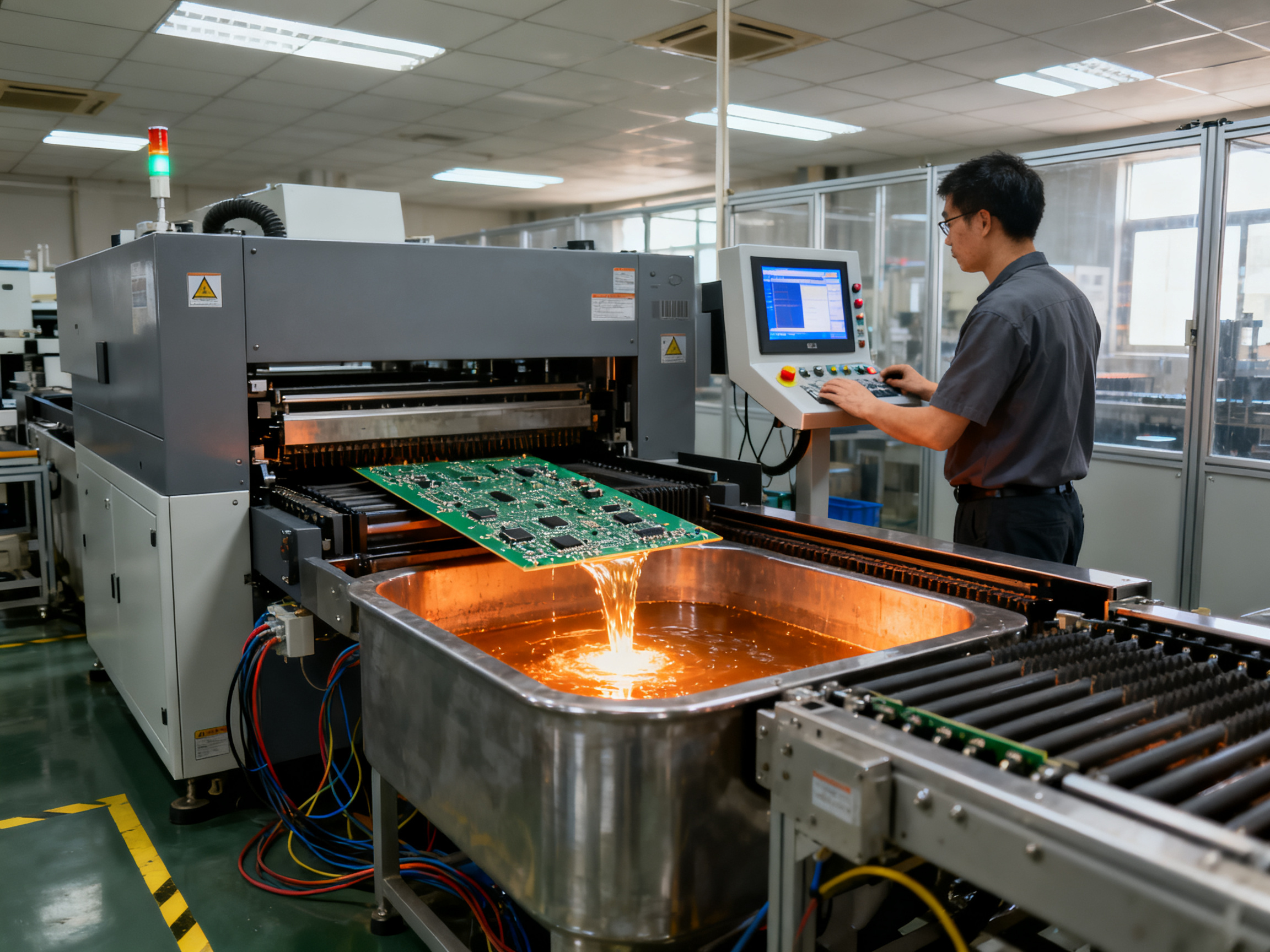
Wave soldering is one of the old workhorses of electronics manufacturing, and it still pulls its weight in 2026. The process works like this: a PCB travels on a conveyor belt, gets coated with flux on the bottom side, passes through a preheat zone to bring the board up to temperature safely, then skims across the top of a molten solder wave. The wave shape happens because of surface tension, and as the board moves over it, solder wicks up through the plated through-holes and makes connections.
Simple. Direct. Effective for the right boards.
The process flow looks like this:
Flux Application → Preheat Zone → Solder Wave Contact → Cooling → Inspection
Once the board clears the wave, it moves through a cooling section and on to inspection. That is the whole thing. The process has been around since the 1950s, and modern machines have refined it plenty, but the basic idea has not changed much.
Why Wave Soldering Still Makes Sense in 2026
Here is the thing about wave soldering: speed is its biggest win. When you have a high-volume run of straightforward through-hole boards, a well-tuned wave system can process 200 to 300 boards per hour, sometimes more. Some multi-up pallet setups hit 500 to 1,000 boards per hour on simple designs.
Cost per board drops fast at scale. The tooling is relatively cheap compared to selective soldering setups, and once the wave is running clean, the process is consistent. It works best when your board has mostly through-hole parts, minimal SMT on the bottom, and a layout designed for wave access.
The Limits Nobody Talks About Enough
But here is where wave soldering gets tricky. The whole bottom of your board contacts molten solder. Anything that should not get soldered needs to be covered with a mask or pallet. That means extra tooling costs and setup time for each board variant.
The thermal hit is real too. Every component on the board gets preheated and then exposed to the wave. Heat-sensitive parts can get damaged, and that means you either need to protect them with fixtures or move them to the top side only.
Solder bridging becomes a real risk when you have tight pin spacing. Dense, mixed-technology boards often just do not work with wave. The wave cannot get to certain areas, and double-sided assemblies are usually off the table because components on the bottom side block wave access.
Modern electronics keep getting more complex. That is pushing more manufacturers toward selective soldering for boards that wave simply cannot handle well.
Expert Tip: Before comparing wave to selective soldering output, validate your fluxing, preheat, conveyor speed, and solder pot temperature. These four parameters drive about 80% of wave soldering defects, and getting them dialed in first means your comparison data will actually mean something.
| What Works Well | Where It Struggles |
|—|—|
| High-volume through-hole boards | Dense mixed-technology assemblies |
| Simple, consistent layouts | Double-sided SMT assemblies |
| Cost-sensitive production runs | Heat-sensitive components |
| Standardized board families | Frequent design changes |
Wave soldering is far from dead in 2026. It just is not the right choice for as many applications as it used to be.## What Is Selective Soldering? Process, Strengths, and Limits
Selective soldering is the opposite of wave soldering in almost every way. Instead of dunking your whole board in molten solder, a selective soldering system targets only the specific through-hole joints that need to be connected. Everything else stays untouched.
Think of it like using a precision airbrush instead of spray paint. You control exactly where the solder goes, how much lands there, and when it stops.
The selective wave soldering process works in five steps:
Localized Fluxing → Controlled Preheat → Nozzle-Based Soldering → Motion Programming → Post-Process Inspection
First, a mini-spray or drop-jet system applies flux exactly where needed. No wasted chemical, no contamination on nearby components. Then a localized preheater brings just that section up to temperature. The solder comes from a programmable nozzle that creates a small, focused fountain or wave exactly where the joint sits. Motion systems move the board or nozzle along a programmed path, hitting each joint in sequence. Finally, inspection verifies the results.
The whole thing runs from a recipe. Change the board design? Update the program. No new pallets, no physical retooling.
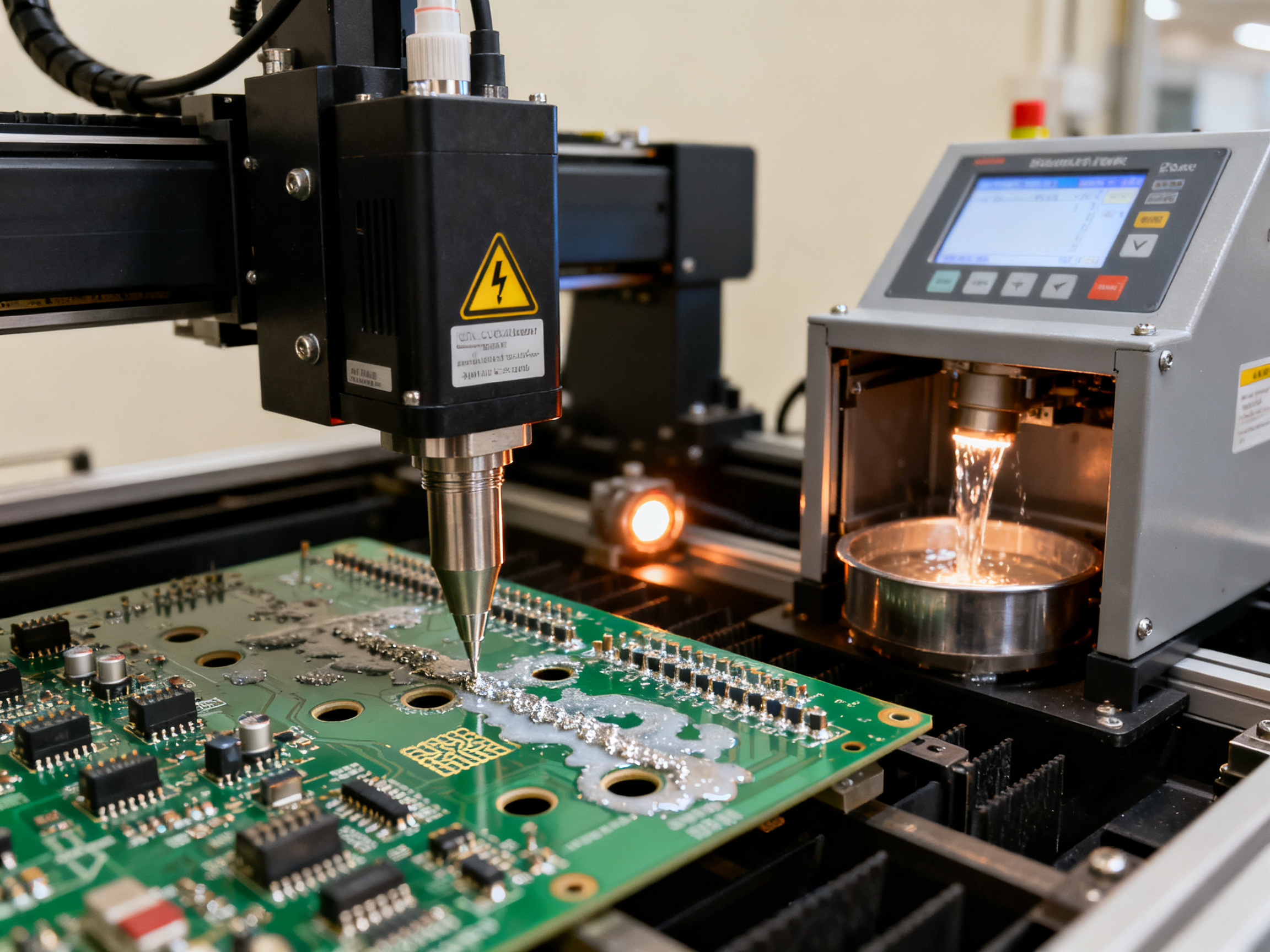
Pro Insight: Selective soldering shines on boards with BGA, QFN, or other heat-sensitive components already mounted on top. We have seen dense mixed-technology assemblies where wave would destroy nearby parts, but selective hits only the through-hole pins without touching anything else.
Where Selective Soldering Wins
The strengths line up with modern board challenges. Mixed technology PCB soldering is the biggest one. When your board has SMT on both sides plus through-hole connectors, selective soldering handles it without masks or damage. High-density assemblies with tight pin spacing work fine because the nozzle size matches the joint. Thermal-sensitive components stay safe because heat stays local.
Limited solder-side clearance used to be a nightmare. Now selective systems navigate keep-out zones, fit around existing components, and handle double-sided assemblies without special fixtures.
The Honest Limits
Speed is the trade-off. A complex board with 200 joints might take 3 to 5 minutes. Wave would do the same board in 20 seconds. For pure throughput on simple through-hole boards, wave still wins.
Selective Soldering Workflow
┌─────────────┐    ┌─────────────┐    ┌─────────────┐    ┌─────────────┐    ┌─────────────┐
│   BOARD    │───▶│   FLUXING   │───▶│   PREHEAT   │───▶│  SOLDERING  │───▶│  INSPECTION │
│   ENTRY    │    │  (Targeted) │    │ (Localized) │    │  (Nozzle)   │    │    (AOI)    │
└─────────────┘    └─────────────┘    └─────────────┘    └─────────────┘    └─────────────┘
     ↓                   ↓                  ↓                   ↓
  Conveyor         Mini-spray or        Focused IR         Programmable
  input rail      drop-jet flux        or convection      solder fountain
                                       heating            or mini-wave
Selective Wave Soldering vs Point-to-Point Selective Soldering
| Feature | Selective Wave Soldering | Point-to-Point Selective Soldering |
|—|—|—|
| Solder source | Continuous mini-wave in a nozzle | Single solder pot with iron or jet |
| Best for | Groups of joints in a line or pattern | Single joints or small scattered pads |
| Speed | Faster for multiple joints in sequence | Slower but more precise |
| Typical use | Connectors, pin arrays | Oddly placed through-holes |
For most mixed-technology boards in 2026, selective wave soldering covers the majority of use cases. Point-to-point steps in for repairs, odd geometries, or boards with components so tightly packed that even a mini-wave nozzle cannot fit.
The Core Differences: How Each Process Approaches Your Board
Here’s where the rubber meets the road. Wave soldering and selective soldering look similar on paper, but they operate on completely different philosophies. Understanding these differences is what separates production managers who make smart equipment calls from those who end up with expensive rework bills.
Board coverage is the most fundamental difference. Wave soldering treats the entire solder side of your board as fair game. Every through-hole on the bottom gets exposed to molten solder, whether it needs it or not. Selective soldering? It only touches the joints you program it to touch. Everything else stays exactly as it was when it came off the pick-and-place line.
That distinction sounds simple, but it changes everything about how you design boards and run production.
Process control tells the same story from a different angle. Wave soldering prioritizes stable, repeatable mass throughput. Once you dial in your preheat, conveyor speed, and wave height, the process runs itself. The tradeoff is that you’re working with broad strokes. Flux gets sprayed everywhere. Heat hits the whole board. Your control is over the machine parameters, not the individual joints.
Selective soldering flips that script. You control flux application at the nozzle level. You control exactly how much heat lands on each joint. You control dwell time, solder volume, and nozzle path with precision. That granularity matters enormously when your board has BGA components sitting two millimeters from a through-hole pin.
Pro Insight: Why per-board cost can favor wave soldering at high volume, while total cost of quality may favor selective soldering for dense mixed-technology assemblies. The math changes depending on whether you’re counting chips or counting headaches.
Product fit is where most production managers make or break their decision. Wave soldering performs best when your board is predominantly through-hole with simple, open layouts. Think power supplies, industrial control boards, basic connectors. The kind of products that don’t change much between revisions and run in batches of thousands.
Selective soldering shines in a completely different world. Mixed technology PCB assembly is its bread and butter. When your board combines SMT on both sides with through-hole connectors, selective soldering handles it without masks, pallets, or prayer. It works for automotive electronics where reliability standards are brutal. It works for aerospace and military where IPC Class 3 compliance isn’t optional. It works for semiconductor equipment where thermal-sensitive components simply cannot survive a full wave.
Here’s a practical example from production floor experience. We ran a batch of motor control boards through wave soldering. The boards had acceptable first-pass yield on a simple day, but when we switched to boards with QFN packages near the connector headers, the rework station lit up like Christmas lights. Solder splatter from the wave found its way under the QFNs. Defects jumped from under 2% to nearly 8%. A switch to selective soldering on that same board design brought defects back under 1%, even though the cycle time was longer.
The longer cycle time cost us maybe 15 seconds per board. The rework on those wave-soldered boards cost us hours and a whole lot of finger-pointing in the quality meeting.
| Comparison Factor | Wave Soldering | Selective Soldering |
|—|—|—|
| Board Coverage | Entire solder side exposed | Only programmed joints |
| Flux Application | Global spray | Targeted mini-spray or drop-jet |
| Heat Impact | Full board exposure | Localized to joint areas |
| Process Control | Machine-level parameters | Individual joint control |
| Masking Needs | Masks or pallets required | Typically none needed |
| Best Board Profile | Simple, TH-dominant layouts | Dense mixed-technology |
| Changeover Speed | Slow (new pallets needed) | Fast (program updates) |
| Double-Sided Boards | Limited or not possible | Fully supported |
| Throughput | 200-300+ BPH standard | 20-100 BPH depending on config |
| Labor Requirements | 6-7 operators typical | 2 operators typical |
The real question isn’t which process is better. It’s which process fits your specific board mix, your quality requirements, and your production volume. Most facilities in 2026 end up with both, using each for what it does best.
But we’ll dig into the decision framework more in the next section, so stay with me.
Cost Comparison: Equipment, Tooling, Labor, Rework, and ROI
Here is where the conversation gets real. Money talks, and the choice between wave soldering and selective soldering comes down to what comes out of your budget, year after year.
The Numbers Behind Each Machine
Wave soldering machines generally cost less upfront than selective soldering systems. A solid wave system might run you $80,000 to $150,000 depending on configuration. A capable selective system? You are looking at $120,000 to $300,000 or more for the advanced stuff with multi-nozzle setups and smart monitoring.
But here is the twist. That upfront gap shrinks fast when you factor in everything else.
Nitrogen consumption is a big one. Wave soldering requires bulk nitrogen to shield that massive molten bath 24/7. The bills add up quickly, especially for lead-free processes that run hotter. Selective soldering uses localized shrouds, so your nitrogen use drops significantly. We are talking potentially 60-70% less consumption depending on your board mix.
Solder waste follows the same pattern. Wave soldering loses material to oxidation, overflow, and dross constantly. Selective systems apply solder only where needed, so waste stays minimal. For a high-volume operation running SAC305, that difference translates to real dollars every quarter.
Pallet and mask costs catch a lot of people off guard. Wave soldering almost always requires custom fixtures to protect SMT areas and keep solder where it belongs. Each board variant needs its own tooling. Change your product often? Those costs multiply fast. Selective soldering typically needs no masking at all. Program the path, load the board, done.
Labor is another place where selective pulls ahead. Wave lines typically need 6 to 7 operators to run smoothly. Selective systems? Usually 2. That difference covers a lot of equipment amortization.
Pro Insight: Why per-board cost can favor wave soldering at high volume, while total cost of quality may favor selective soldering for dense mixed-technology assemblies. The math changes depending on whether you are counting chips or counting headaches.
ROI Reality Check
Case studies from manufacturers running mixed-technology boards show some striking numbers. First-pass defects dropped 20-30% after switching to selective soldering compared to hand soldering, and 10-15% compared to mini-wave methods. Conversion costs fell 51-78% per board assembly by eliminating secondary operations and rework.
One manufacturer running complex automotive boards reported 18% lower overall cost per board with selective soldering compared to wave, despite the longer cycle time. The rework savings and reduced scrap made the difference.
| Cost Factor | Wave Soldering | Selective Soldering |
|—|—|—|
| Equipment Investment | $80K – $150K | $120K – $300K+ |
| Nitrogen Consumption | High (bulk shielding) | Low to moderate (localized) |
| Solder Waste | High (oxidation, overflow) | Low (precise application) |
| Tooling per Board Variant | Custom pallets/masks | Program update only |
| Labor Headcount | 6-7 operators | 2 operators |
| Defect Rate | 2-5% typical | Under 1% typical |
| Rework Cost | Higher (thermal damage risk) | Lower (localized process) |
Real pricing depends heavily on your specific configuration, line integration, and process requirements. Get detailed quotes and run the numbers for your actual board mix before deciding.
ROI Calculation Template for Your Facility
To figure out which process makes sense for your operation, track these categories over a 12-month period:
Annual Costs to Track:
- Equipment depreciation and financing
- Nitrogen consumption and cost
- Solder and flux consumption
- Pallet and mask tooling (wave) or programming time (selective)
- Direct labor for operation and supervision
- Rework hours and scrap rates
- Maintenance parts and service contracts
Calculate:
- Total annual cost for each process
- Divide by expected annual board volume
- Add cost per defect (rework hours plus scrap value)
- Compare total cost per good board, not just cost per board
The process that wins on raw cycle time might lose on total cost when rework and scrap enter the picture.
When Wave Makes Financial Sense
If your boards are mostly through-hole, your designs are stable, and you run tens of thousands of identical units per year, wave soldering almost always wins on pure cost per board. The math is simple: spread your tooling investment over a huge volume, keep operators running at peak speed, and collect the savings.
When Selective Makes Financial Sense
If your boards mix BGA, QFN, and through-hole parts, if you face frequent design changes, or if your quality standards demand IPC Class 3 compliance, selective soldering usually wins on total cost of ownership. The defects you prevent cost more than the extra cycle time you absorb.
Most facilities in 2026 end up running both. Use each for what it does best, and let the numbers guide you.
Speed and Throughput: Selective Soldering Speed vs Wave Soldering
Let us talk numbers, because at the end of the day, your production schedule does not lie.
Wave soldering typically processes 200 to 300 boards per hour on standard setups. Push it with multi-up pallets on simple connector-heavy boards, and you can hit 500 to 1,000 boards per hour. The wave does not care about joint count. It hits everything at once, and that is the speed advantage in a nutshell.
Selective soldering runs 20 to 50 boards per hour with a single nozzle. But here is where it gets interesting: multi-nozzle systems and parallel processing can push that to 50 to 100 boards per hour on complex assemblies. That sounds slow compared to wave, and it is, but you have to ask yourself what you are actually measuring.
From Our Experience: A board that takes 3 minutes in selective soldering might take 20 seconds in wave. But if that wave-soldered board then needs 15 minutes of rework and you lose 2% of your batch? Your effective throughput just collapsed. Line balance and first-pass yield matter more than the nominal soldering speed on the spec sheet.
Selective soldering speed depends on several things. Joint count is the big one. The more through-hole pins you need to solder, the longer the program takes. Nozzle path optimization matters too. A smart motion path beats a sloppy one every time. Fluxing strategy, preheat time, and whether you have multi-nozzle capability all factor in.
| Throughput Comparison | Wave Soldering | Selective Soldering (Single Nozzle) | Selective Soldering (Multi-Nozzle) |
|—|—|—|—|
| Nominal Speed | 200-300 BPH | 20-50 BPH | 50-100+ BPH |
| Best Case | 500-1,000 BPH | 50-60 BPH | 100-120 BPH |
| What Drives It | Conveyor speed, wave contact time | Joint count, path efficiency | Parallel processing capability |
The real takeaway? Wave wins on raw speed for compatible boards. Selective wins on effective throughput when you factor in defects, rework, and the fact that most modern boards are not wave-friendly without masks and prayers.
We have watched lines where selective actually beat wave on overall output because the wave line kept stopping for pallet changes and the selective line just kept running clean boards. Speed means nothing if your yield is garbage.## Quality and Defect Control for High-Reliability Assemblies
Let us get into the messy part. Defects. Because no matter how shiny your equipment is, if your boards come out with bad joints, you have a problem.
How Defects Differ Between the Two Processes
Wave soldering and selective soldering fail in completely different ways. Knowing what can go wrong helps you prevent it.
Wave soldering defects tend to cluster around a few recurring problems:
Solder bridges form when molten solder connects two pins that should stay separate. Tight pin spacing makes this worse. Solder balls scatter across the board when flux pops or the wave agitates too violently. Skips happen when a through-hole just does not get enough solder, leaving you with a cold joint that will fail in the field. And thermal stress cracks your board or damages nearby components because the whole assembly gets cooked.
Selective soldering has its own failure modes:
Programming errors send the nozzle to the wrong spots, skipping joints entirely. Nozzle wear or misalignment causes incomplete fills. Flux coverage gaps mean some joints do not wet properly. And if your solder temperature or dwell time is off, you get insufficient hole fill that looks OK visually but fails under stress.
| Defect Type | Wave Soldering Risk | Selective Soldering Risk | Prevention Focus |
|—|—|—|—|
| Solder Bridging | High (whole board exposed) | Low (localized) | Pin spacing, nozzle sizing |
| Solder Balls | Moderate | Moderate | Preheat, flux control |
| Skips/Misses | Low | Moderate (programming) | Verification, AOI |
| Insufficient Fill | Moderate | Moderate | Temperature, flux, dwell |
| Thermal Damage | High (full board) | Low (localized) | Process window control |
| Icicles/Tear-Drops | Moderate | Moderate | Withdrawal speed, temp control |
From Our Experience: A practical decision tree for production managers choosing equipment based on board design, throughput, defect risk, labor availability, and compliance needs.
Why High-Reliability Industries Care More About Quality Than Speed
Here is the thing that separates automotive, aerospace, and medical manufacturers from everyone else. They do not care if your line runs 300 boards per hour if 2% of them will fail in the field.
For IPC Class 3 compliance, you need at least 75% hole fill, clean wetting on all sides, and zero visual defects that violate IPC-A-610 criteria. Wave soldering can hit those marks, but only on boards designed for it. Put a BGA two millimeters from a through-hole pin, and the wave will find ways to cause problems you cannot see until your customer finds them.
Selective soldering gives you process traceability. You can log every joint temperature, every flux application, every dwell time. When your quality team asks what happened on board serial number 47, your selective system has the answer. Your wave system just tells you it ran a batch.
The BGA and QFN Problem
Dense boards with BGA or QFN components near through-hole pins represent the worst-case scenario for wave soldering. The whole bottom of the board gets exposed to solder, and those tiny packages sit right there, absorbing heat they were never designed to handle.
We have seen QFN pads lifted off boards after wave exposure. The solder wicks under the package during the wave contact, and when it cools, it takes the termination with it. Rework for that damage costs more than the original board.
Selective soldering sidesteps this completely. The nozzle targets only the through-hole pins. Everything else stays at ambient temperature. That heat-sensitive BGA next to your connector header never even knows soldering happened.
The other headache is pallet complexity. Wave soldering dense boards often requires custom pallets with cutouts for every component that cannot touch solder. Those pallets cost money, take time to make, and become obsolete every time your board design changes. Selective soldering typically needs no masking at all. Program the path, load the board, go.## Decision Framework: When to Use Selective Soldering vs Wave Soldering
So you are standing in front of your line, trying to figure out which process actually makes sense for your boards. Let us make this simple.
Use wave soldering when:
- Your board designs are stable and have been running for years
- Through-hole density is high and layouts are open and wave-friendly
- Solder-side components can handle full thermal exposure
- Maximum volume throughput is your dominant requirement
- You are running tens of thousands of identical units per year
Use selective soldering when:
- Your assemblies are dense with mixed technology (BGA, QFN, through-hole)
- Components are heat-sensitive and need protection
- Your products change designs often
- You need precise control around specific joints
- Compliance standards like IPC Class 3 apply
- Double-sided boards are in your mix
Use Case Decision Table
| Your Situation | Recommended Process | Why |
|—|—|—|
| High-volume simple through-hole boards | Wave soldering | Speed and low per-board cost |
| Mixed-technology with BGA/QFN nearby | Selective soldering | Prevents thermal damage |
| Frequent design changes | Selective soldering | No new pallets needed |
| Automotive safety systems | Selective soldering | Meets Class 3 compliance |
| Industrial power supplies | Wave soldering | High THT density, stable designs |
| Prototype runs | Selective soldering | Flexible, low setup cost |
| Double-sided assemblies | Selective soldering | Handles complex layouts |
Weighted Scoring Matrix
When the decision is not obvious, score your board against these factors:
| Factor | Weight | Wave Score | Selective Score |
|—|—|—|—|
| Volume (high = wave) | 20% | /20 | /10 |
| Complexity (high = selective) | 25% | /5 | /25 |
| Quality requirements (Class 3 = selective) | 20% | /5 | /20 |
| Changeover frequency (high = selective) | 15% | /5 | /15 |
| Labor availability (low = selective) | 10% | /3 | /10 |
| Heat sensitivity (present = selective) | 10% | /2 | /10 |
| Maximum Possible | 100% | 40 | 90 |
A score above 60 for selective suggests that process. Below 40 favors wave. The middle ground is where most boards land, and that is where a hybrid strategy makes the most sense.
From Our Experience: A practical decision tree for production managers choosing equipment based on board design, throughput, defect risk, labor availability, and compliance needs.
The Hybrid Approach That Works
Most shops in 2026 end up running both. They use wave soldering for simple connector boards and reserve selective soldering for complex assemblies, prototypes, and high-reliability lines. S&M Co. Ltd. equipment supports this workflow with systems designed for flexible integration across both process types.
The key is knowing which boards go where before you commit to tooling. Run the math on your defect rates, your rework costs, and your changeover time. That data tells the story better than any rule of thumb.## Integration Considerations for Modern SMT Production Lines
Getting your wave or selective soldering machine to work with the rest of your line involves more than plugging it in. Conveyor width and SMEMA compatibility determine whether boards move through smoothly or require manual handling at every transition. If your pick-and-place outputs 400mm boards and your selective solder station only handles 300mm, you are creating a bottleneck that kills throughput. SMEMA or IPC-CFX protocols let machines communicate status and commands, so verifying protocol compatibility upfront prevents integration headaches later.
Most operations run through an MES in 2026, which means your soldering equipment needs to log real-time data like temperature profiles, cycle counts, and defect information. This traceability matters for quality teams and for proving compliance with standards like IPC-A-610. Without proper MES integration, you are manually recording data that should flow automatically, and that creates both labor costs and error risks.
Your floor layout tells the real story of whether integration will work. Soldering machines need clearance for maintenance access, nitrogen supply lines, and proper ventilation to handle fumes. Wave machines are the bigger footprint problem here. A typical wave solder station needs 3 to 4 meters of linear space plus room for the solder pot maintenance. Selective systems are more compact, which often makes them easier to fit into existing layouts.
The nitrogen purity question also matters more for lead-free processes, where 99.999% purity becomes essential for keeping defects low and wetting consistent. Plan your supply infrastructure before the machine arrives.
Training and changeover speed are where operators feel the daily impact. Wave systems demand mask and pallet changes for each board variant, so expect 30 to 60 minutes of setup time per changeover. Selective soldering requires program selection and board loading, which typically takes 5 to 15 minutes. That difference compounds across high-mix production where you are switching products frequently.
From Our Experience: A practical decision tree for production managers choosing equipment based on board design, throughput, defect risk, labor availability, and compliance needs.
Planning ahead means thinking about scalability for new products. Lead-free compliance requirements are already shaping equipment choices, and 2026 standards demand nitrogen inerting and tighter temperature control across most applications. Your soldering equipment needs to handle these requirements without constant retooling. Modular systems let you add fluxing stations or extra solder pots as your product mix evolves. This flexibility becomes valuable when you are managing automotive, aerospace, and consumer electronics on the same floor, each with different compliance demands.
SMT Line Integration Checklist
| Checkpoint | What to Verify |
|—|—|
| Conveyor Compatibility | Match board width, thickness, and SMEMA protocol version |
| MES Integration | Confirm IPC-CFX or OPC UA data logging capability |
| Nitrogen Supply | Verify purity level (99.999% for lead-free) and flow capacity |
| Footprint Clearances | Account for maintenance access and ventilation requirements |
| Changeover Time | Measure actual setup time for each board variant |
| Training Requirements | Match operator skills to process complexity |
| Scalability | Confirm modular expansion options for future product lines |
Expert Conclusion: Choose the Process That Protects Yield and Scale
Here is the bottom line after all the comparison data, defect rates, and cost breakdowns.
Wave soldering and selective soldering are not competing for the same job. They solve different problems, and picking the wrong one for your board mix costs more than the equipment price tag ever shows.
Wave soldering delivers raw speed for compatible boards. If your through-hole designs are stable, your layouts are open, and you are running tens of thousands of identical units per year, wave gets the job done at the lowest cost per board. That math is straightforward.
Selective soldering delivers precision for complex assemblies. If your boards mix BGA, QFN, and through-hole components, if your products change frequently, or if compliance standards like IPC Class 3 are non-negotiable, selective soldering protects your yield and your reputation. The defect data does not lie. Lower rework rates, fewer field failures, and traceable process data add up to real savings over time.
The decision should never be about machine price alone. It should be about total cost of quality, and that includes defects you prevent, rework you avoid, and compliance risks you sidestep.
Final Recommendation at a Glance
| Your Situation | Go With | Key Reason |
|—|—|—|
| High-volume, simple through-hole boards | Wave soldering | Lowest cost per unit at scale |
| Mixed-technology, dense assemblies | Selective soldering | Prevents defects and thermal damage |
| Frequent design changes | Selective soldering | No pallet retooling needed |
| IPC Class 3 compliance required | Selective soldering | Process control and traceability |
| Automotive, aerospace, or medical | Selective soldering | Meets reliability standards |
| Prototype or low-volume runs | Selective soldering | Fast changeover, low setup cost |
Your Next Steps
Audit your board families against these criteria. Quantify your current defect and rework costs so the comparison is real, not hypothetical. Map your throughput requirements and identify where bottlenecks actually live. Then reach out for a process evaluation or equipment consultation with your specific numbers in hand.
S&M Co. Ltd. offers equipment across both process types, designed for flexible integration into existing SMT lines. Whether you need the throughput of wave soldering for simple connectors or the precision of selective soldering for complex assemblies, matching the process to your product mix is where the real gains hide.
Expert Conclusion: The choice between wave and selective soldering in 2026 comes down to a single question: what does your board actually need? High-volume, wave-friendly layouts favor the speed and low per-board cost of wave soldering. Complex mixed-technology assemblies favor the precision, yield protection, and compliance advantages of selective soldering. Smart manufacturers in 2026 run both, using each process where it delivers the most value. The goal is not to pick a winner. It is to match the process to the product and let your defect data guide the decision.