
Published: 25 May 2026
Reading Time: 12 minutes
Reviewer: Jace Liu, Engineer specializing in SMT systems and precision electronics manufacturing
Introduction and Importance of Proper Setup
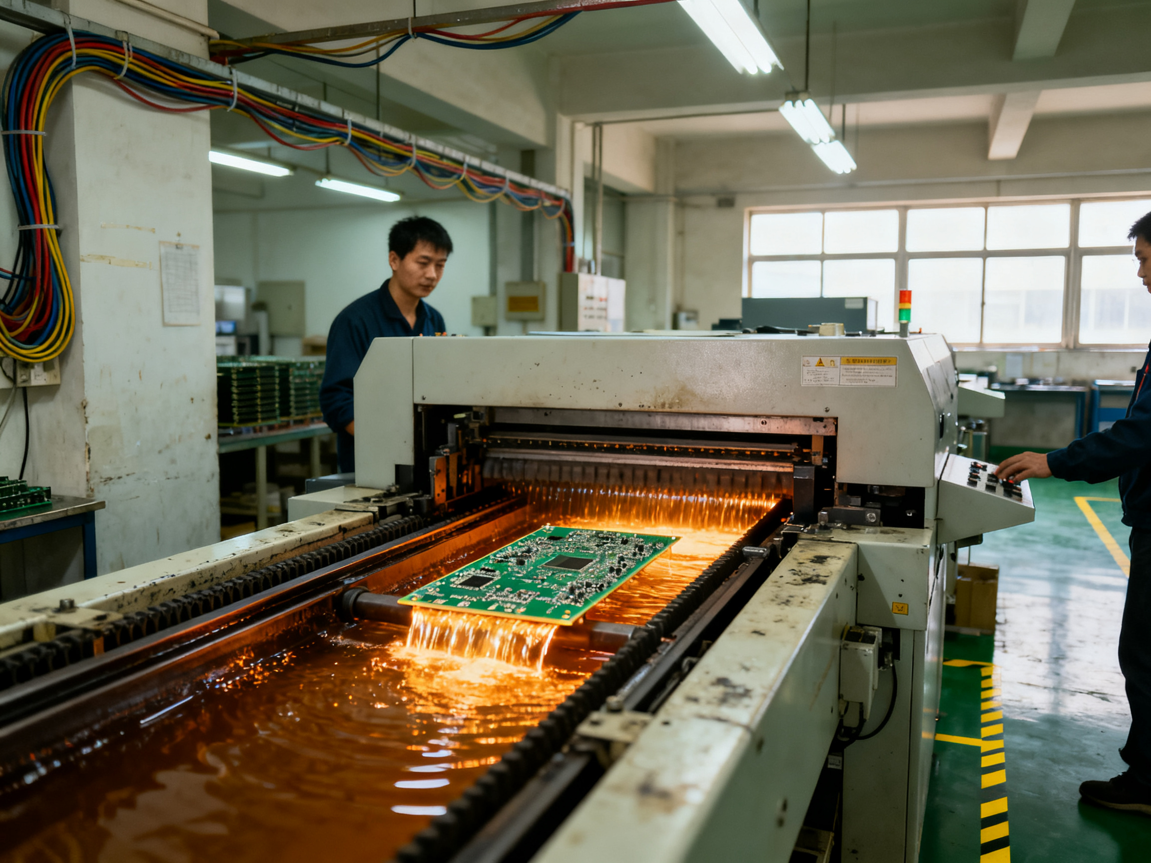
If you’ve ever watched a wave soldering machine in action, you know it looks almost hypnotic. Liquid solder surges up in a smooth wave, and PCBs glide across like they’re getting a secret bath. But here’s what nobody tells you until they mess it up: getting that process right requires careful setup and configuration. Without it, you’re looking at bridging defects, cold joints, and components that just won’t cooperate.
Wave soldering has been a staple in electronics manufacturing for decades. It’s the go-to method for through-hole components and mixed-technology assemblies. The basic idea is simple. Molten solder forms a wave, and your PCB passes through it, picking up solder at the joints. Easy, right?
Not so fast. The real challenge lies in balancing temperature, timing, flux application, and wave height. Get any of these wrong, and you’ll see defects pop up. Common problems include bridging (when solder connects things it shouldn’t), insufficient solder coverage, cold joints, and shadowing where tall components block the wave. There’s also the risk of thermal stress damaging your boards or components.
This wave soldering guide walks you through everything you need to know about wave soldering machine setup. We’ll cover the setup process step by step, share practical tips for getting your solder temperature profile right, and help you troubleshoot common issues. By the end, you’ll have the knowledge to configure your wave solder machine for reliable, consistent results.
Jace Liu is a seasoned engineer specializing in Surface Mount Technology (SMT) systems and precision electronics manufacturing. With over a decade of experience, Jace has overseen the installation and optimization of advanced soldering equipment for leading manufacturers worldwide.
Step-by-Step Guide to Machine Calibration
So now that we understand why wave soldering setup matters, let’s get into the actual process. I’ve calibrated dozens of these machines over the years, and here’s the thing: there is no one-size-fits-all approach. Your setup will depend on your board design, component heights, and the specific solder alloy you’re using.
But there are core steps that apply every single time. Let’s walk through them.
Preparing Your Machine and Workspace
First things first: clean your workspace. I know it sounds obvious, but you’d be surprised how much debris finds its way into solder baths. Before firing up your wave soldering machine, inspect the solder pot for oxidation and contaminants. Old solder builds up flux residue and oxides that directly impact wetting quality.
Check your nitrogen inerting system if your machine has one. Nitrogen helps prevent oxidation during the soldering process, but you need proper flow rates. Too little nitrogen, and oxidation becomes a problem again. Too much, and you’re wasting gas and money.
Also, verify that your flux applicator is delivering consistent coverage. Uneven flux application causes all sorts of headaches, from insufficient solder joints to bridging defects. Run a test spray pattern and check that the mist is fine and uniform across your board width.
Expert Tip: Before you start any calibration, document your baseline settings. Take photos of your initial configuration, write down all your starting parameters, and keep a calibration log. This makes troubleshooting way easier when something goes sideways, and it helps you replicate successful setups on similar boards.
Configuring Solder Temperature Profiles
Temperature is where most people struggle. The solder bath needs to be hot enough to melt your alloy and create good wetting, but not so hot that it damages components or creates excessive dross.
For lead-based solders, you’re typically looking at a bath temperature around 250 degrees Celsius. Lead-free alloys run hotter, usually in the 260 to 280 degree range. But here’s the catch: your bath temperature isn’t the whole story. The actual temperature at the joint depends on your preheat settings, conveyor speed, and how long the board spends in contact with the wave.
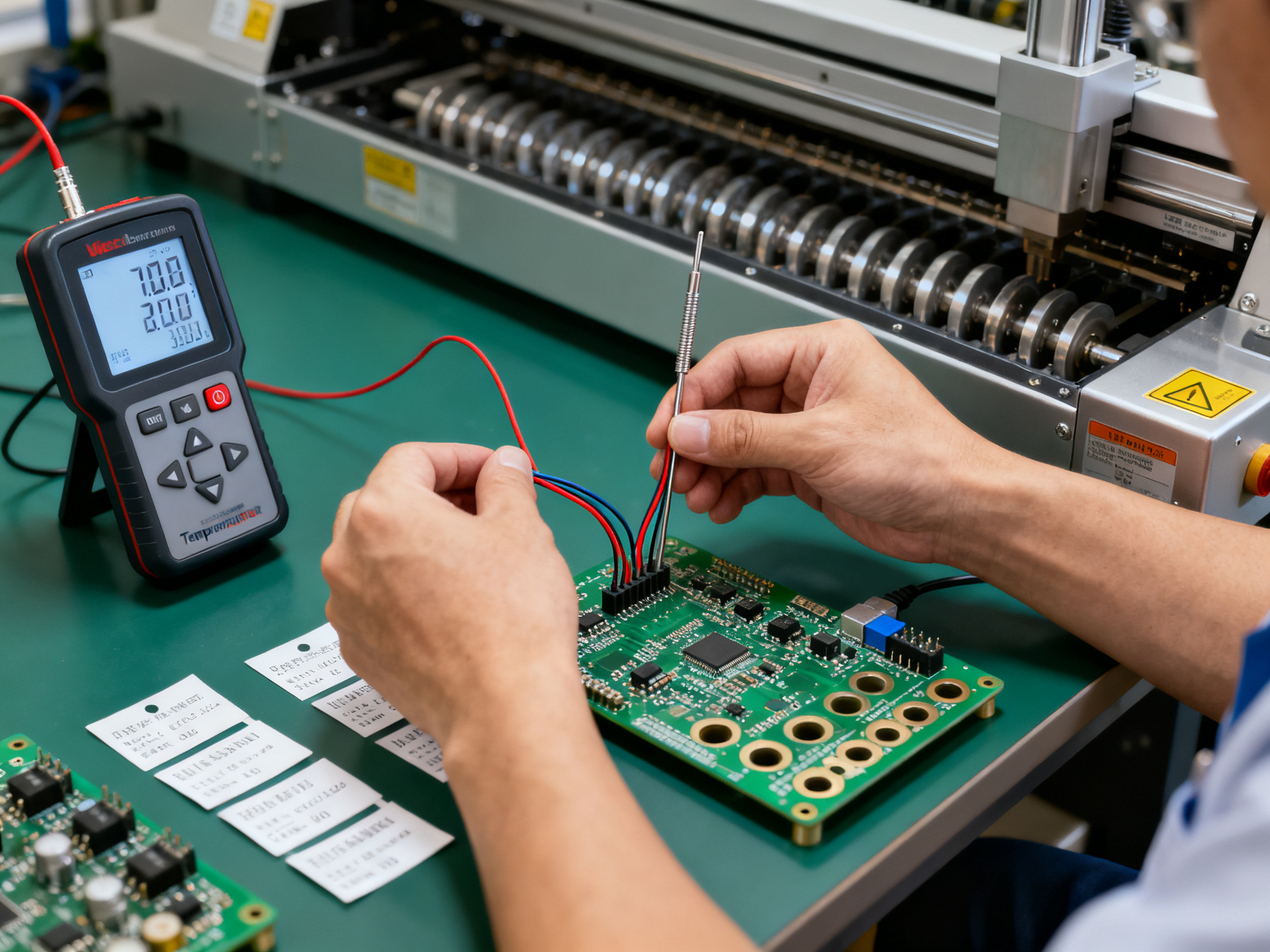
Start with your solder paste manufacturer’s recommendations as a baseline, then adjust based on what you see. We always place thermocouples on trial boards to measure actual temperatures at different points during the process. Large copper areas tend to absorb more heat, so they might need slower conveyor speeds or higher preheat temperatures to reach proper wetting.
Your preheat zone serves two purposes. It activates the flux and brings the board up to temperature gradually. Too rapid a temperature ramp, and you’ll get thermal stress damage. Too slow, and your flux pre-activates before reaching the wave, losing its cleaning ability.
Aim for a preheat ramp of about 1.5 to 3 degrees Celsius per second. Your target board temperature entering the wave should be somewhere between 150 and 190 degrees Celsius, depending on your alloy and board thickness.
Adjusting Conveyor Speeds and Component Alignment
Conveyor speed controls your contact time with the solder wave. Faster speeds mean shorter contact times, which can work for thinner boards with heat-sensitive components. Slower speeds give more time for solder to flow into plated-through holes and create robust joints.
Most setups run between 1 and 2 meters per minute, but your sweet spot depends on your specific board characteristics. Here’s a practical test: run a board with test coupons that include through-hole components. Check the fill rate on those holes. You want 75 to 100 percent hole fill, meaning the solder should travel most or all of the way through the hole.
Component alignment matters too, obviously. But it’s not just about placement accuracy. Tall components create shadows that block the solder wave from reaching components behind them. If you’re dealing with mixed technology boards with both through-hole and surface mount components, you might need to adjust your wave shape or use a beta wave (a secondary smaller wave that follows the main wave) to minimize shadowing effects.
When you first set up a new board configuration, run a few test boards before committing to full production. Check for bridging between fine-pitch components, inspect the solder fill on through-hole joints, and look for any signs of thermal damage. Make small adjustments, one parameter at a time, so you know what’s working and what isn’t.
Calibration isn’t a one-time thing either. Over time, solder composition changes, flux residues build up, and heating elements wear. Build regular maintenance into your schedule, and you’ll catch problems before they become production headaches. For more insights on reducing defects and optimizing your wave soldering process, explore our detailed resources on soldering equipment and SMT wave soldering best practices.
Citations: Wave Soldering for SMT | Precision in PCB Assembly | Reflow Soldering Profile Guide
Adjustments for Various Component Types and Compatibility
Not all boards are created equal, and your wave soldering setup needs to flex accordingly. What works for a simple through-hole assembly might completely fail when you’re dealing with mixed technology boards or sensitive components. Here’s how to adjust your approach based on what you’re building.
Selecting Lead-Free Solder Alloys and Fluxes
Lead-free solders have pretty much taken over in 2026, and for good reason. Environmental regulations and RoHS compliance mean you need the right alloy for the job.
SAC305 (tin-silver-copper) is probably the most common lead-free choice today. It melts around 217 to 221 degrees Celsius and provides good wetting characteristics. But here’s the thing: lead-free solders need higher process temperatures and tighter control. Your bath might run 20 to 30 degrees hotter than leaded setups, so factor that into your thermal stress calculations.
Flux selection matters just as much. No-clean fluxes are popular because they eliminate post-solder cleaning, but they leave residues that might interfere with conformal coating or underfill processes. If you’re working with boards that need coating, a water-soluble flux might be your better option, though you’ll need to factor in cleaning equipment and drying time.
Pro Insight: When switching to a new solder alloy, always run qualification boards first. Test at least 20 units and inspect for bridging, fill issues, and any signs of thermal damage. Document your settings so you can replicate the setup on similar boards.
Ensuring Compatibility with Other SMT Equipment
Your wave solder machine doesn’t exist in isolation. It needs to play nice with your upstream and downstream equipment. Conveyor widths need to match your other handlers. Thermal profiles should complement your reflow oven settings if you’re doing mixed technology.
If you’re running a hybrid line with both surface mount and through-hole components, timing becomes critical. Your paste printer and placement machine set the stage, and your wave solder process needs to handle what comes next without introducing defects that undo earlier work.
Adjusting for Specific Component Types
BGAs and other bottom-terminated components add complexity to wave soldering. These parts can trap air and create shadowing issues that block solder from reaching pads underneath or downstream.
For BGA assemblies, you might need to reduce conveyor speed to give solder more time to flow properly. Some manufacturers use a dual-wave setup with a chaotic pulse wave to break up air pockets. Others add nitrogen inerting to improve wetting under challenging geometries.
Heat-sensitive components require special attention too. Sometimes selective wave soldering makes more sense than full-board wave processing, where you protect certain areas with fixtures or masks while soldering the rest.
The key is knowing your board’s specific challenges and adjusting one variable at a time until you hit the mark.
Advanced Features and Troubleshooting
Even with perfect calibration, stuff happens. Your wave solder machine has built-in features that help you catch problems early, and knowing how to use them saves a ton of rework and wasted boards.
Common Defects and How to Fix Them
Bridging is probably the issue I see most often. That’s when solder connects two pads that should stay separate. Usually it’s caused by too much solder, incorrect wave height, or conveyor speed that’s off. The fix? Check your wave height first, then adjust your conveyor speed, and make sure your flux is applying evenly.
Insufficient solder coverage means your joints look starved. This typically points to poor wetting, which often traces back to preheat problems or contaminated solder. Cold joints look dull and grainy instead of shiny and smooth. They happen when joints don’t get enough heat or contact time. If you’re seeing these, slow down your conveyor and verify your solder temperature is actually hitting your target.
Shadowing occurs when tall components block the solder wave from reaching parts behind them. Mixed technology boards suffer from this big time. A beta wave (that secondary smaller wave I mentioned earlier) can help fill in those shadowed areas. Some machines also let you adjust the wave shape to reach trickier spots.
Pro Insight: Keep a troubleshooting log. Write down every defect you see, the settings when it happened, what you changed, and the results. Over time, you’ll see patterns emerge. This has saved my bacon more times than I can count when similar boards come through months later.
Machine Features for Troubleshooting
Modern wave solder machines come with diagnostic tools that help you catch problems before they become disasters. Real-time temperature monitoring shows you exactly what’s happening in the solder bath and on your boards. Conveyor load monitoring can detect when boards aren’t traveling smoothly, which might indicate alignment issues or jams.
Some systems offer wave height sensors that automatically adjust if the solder level drifts. This is super helpful for high-volume production where small variations compound over time. You can also find machines with integrated inspection cameras that flag obvious defects as boards exit the wave.
For more detailed analysis, thermal profiling software lets you compare actual board temperatures against your target profile. If you’re dealing with recurring issues on specific board designs, this data helps you understand what’s actually happening versus what you think is happening.
Diagnostic Tools for Error Detection
When problems persist, systematic troubleshooting helps you narrow down the root cause. Start with visual inspection of failed boards and note exactly where defects appear. Check your solder bath for contamination; oxidation and flux residues accumulate over time and directly impact wetting quality.
Thermocouple testing verifies that your temperature readings are accurate. Sensors drift, especially after heavy use, so calibration checks should be part of your regular maintenance schedule. If your machine has self-diagnostic features, run them periodically to catch issues you might miss during visual checks.
For persistent problems, consider adding external inspection equipment like X-ray systems for hidden joint analysis or AOI (automated optical inspection) stations. These tools catch defects that human inspectors might overlook, especially on high-density boards where joint access is limited.
The key is using all these tools together. Your machine’s built-in diagnostics tell you if parameters are off. Your inspection equipment tells you if the results look right. Your process logs tell you if problems are getting better or worse over time. When all three align, you know your wave soldering process is under control.
Safety and Environmental Compliance
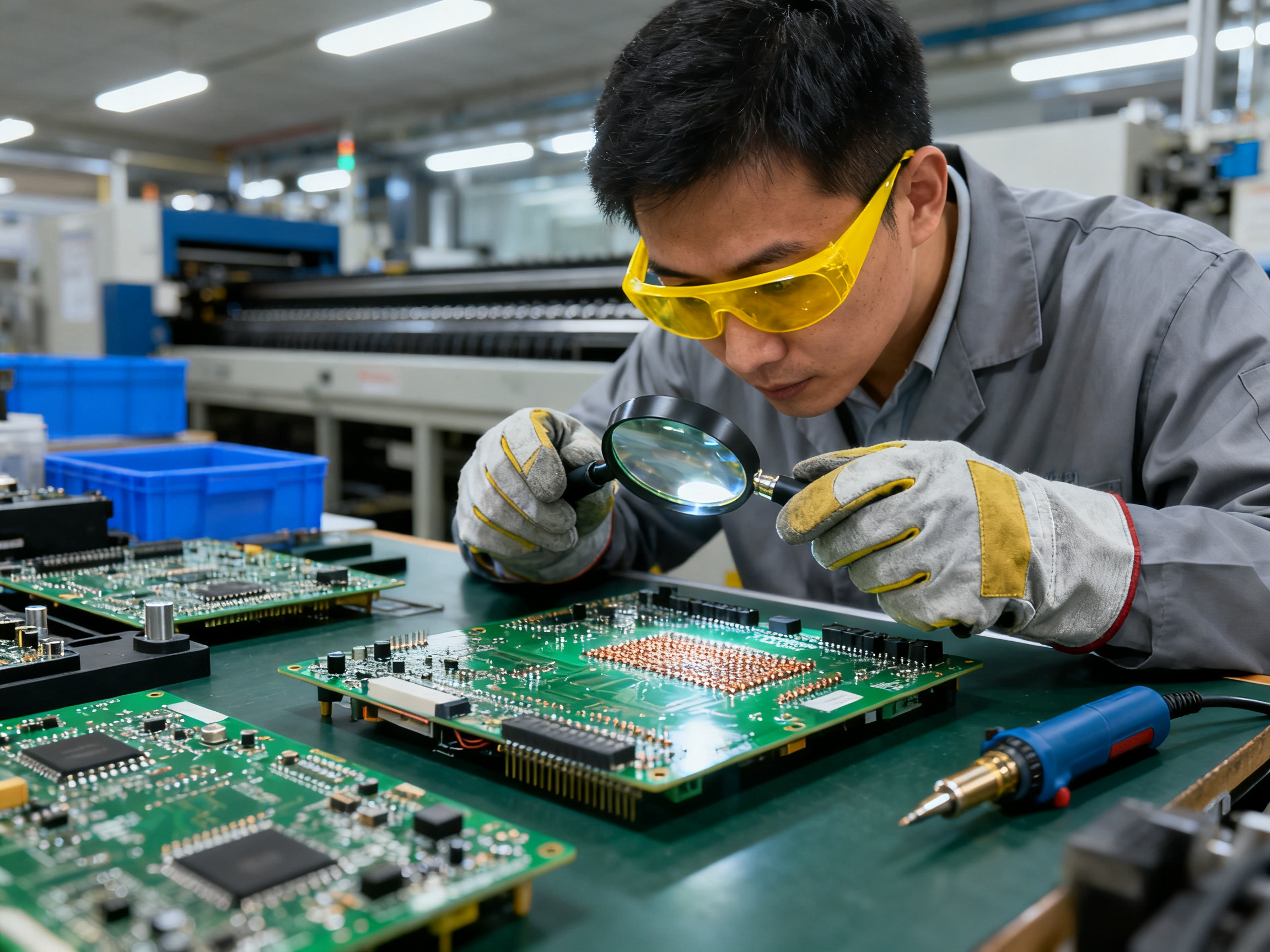
Working with wave soldering equipment means dealing with some serious hazards. Molten solder sits at temperatures around 250 degrees Celsius or higher. That’s hot enough to cause severe burns in a split second if you’re not careful. Proper safety gear is non-negotiable. I’m talking heat-resistant gloves, safety glasses or face shields, and flame-retardant clothing. Your workspace needs good ventilation too, since the fumes from molten solder and flux can cause respiratory issues over time.
Maintenance crews face additional risks when servicing equipment. Before any maintenance work, the machine must cool down completely and be locked out/tagged out to prevent accidental startup. Confined spaces around the solder pot require extra precautions. Establish clear protocols and make sure everyone on the floor understands them. Regular safety training keeps these procedures fresh in everyone’s mind.
Lead-free solders have become standard in 2026, which helps with environmental compliance, but they bring their own considerations. These alloys typically contain tin, silver, and copper, and they require higher processing temperatures. That means more energy consumption and increased oxidation in the solder bath. You need proper exhaust systems to handle the different fume profiles compared to traditional leaded solders.
International standards shape how we work. RoHS compliance restricts hazardous substances in electronic equipment across the EU and many other markets. IPC standards define quality benchmarks for solder joints and manufacturing processes. ISO 9001 provides the framework for quality management systems. Meeting these standards isn’t just about avoiding fines; it proves your commitment to quality and sustainability.
From Our Experience: Schedule quarterly safety audits and keep detailed logs of compliance checks. This documentation protects you during customer audits and helps identify issues before they become problems.
Modern wave soldering equipment from manufacturers like Shenzhen Chuxin Electronic Equipment Co., Ltd. often includes built-in safety features like automatic temperature limiting, emergency shutoffs, and real-time monitoring systems. These tools help you stay compliant while keeping operators safe. When shopping for new equipment, prioritize machines that make safety and compliance easier, not harder.
Conclusion: Key Takeaways for Maximizing Performance
Let’s be real for a second. Wave soldering setup isn’t glamorous work. It involves careful calibration, constant monitoring, and more than a few late nights chasing down that perfect temperature profile. But here’s the thing: when you get it right, everything else falls into place.
Proper wave soldering setup directly impacts your production efficiency, defect rates, and bottom line. The steps we’ve covered—cleaning your workspace, configuring temperature profiles, adjusting conveyor speeds, and fine-tuning for different component types—aren’t suggestions. They’re the foundation of reliable solder joints and consistent quality.
You’ve learned why temperature control matters so much, how to dial in your preheat settings, and what to do when bridging or shadowing shows up on your boards. These aren’t theoretical concepts. Apply them, and you’ll see the difference in your first successful production run.
But don’t stop there. Manufacturing technology keeps evolving. New alloys, tighter tolerances, and stricter environmental standards mean your learning never really ends. Stay curious. Keep logs. Compare results across different board designs. Share what you learn with your team.
If you’re looking to upgrade your equipment or need hands-on guidance with your wave soldering process, Shenzhen Chuxin Electronic Equipment Co., Ltd. offers a range of solutions designed for modern manufacturing demands. Their systems support everything from standard through-hole assemblies to complex mixed-technology boards, with built-in diagnostics that make troubleshooting less of a headache.
The goal isn’t perfection on day one. It’s building a process you can trust, refine, and scale over time. You’ve got the knowledge now. Time to put it to work.