
Published: November 16, 2026
Last updated: November 16, 2026
Reading Time: 14 minutes
Introduction: Why Void Control Changes the Reflow Decision
Picture a Tuesday night shift at an SMT plant in Shenzhen. Boards came off the line and every one of them looked perfect from the top. Then the X-ray showed gas voids hiding inside the solder joints under the BGA arrays. This is the moment a standard reflow oven stops being enough.
Conventional reflow handles most work well. Heat melts the solder paste, the liquid solder wets the pads, and a joint forms. Trouble starts when gas from flux and moisture has nowhere to escape. It stays trapped as voids. On a simple two-pad part, that usually causes no problems. On a BGA, a QFN, or a power module, those voids cut the thermal path and change how the joint behaves over years of service.
Vacuum reflow soldering pulls that gas out while the solder is still liquid. The outcome is usually fewer voids and cleaner joints. But it is not a magic fix. It adds capital cost, eats into cycle time, and creates new maintenance work. Think of it as a process option, not a replacement.
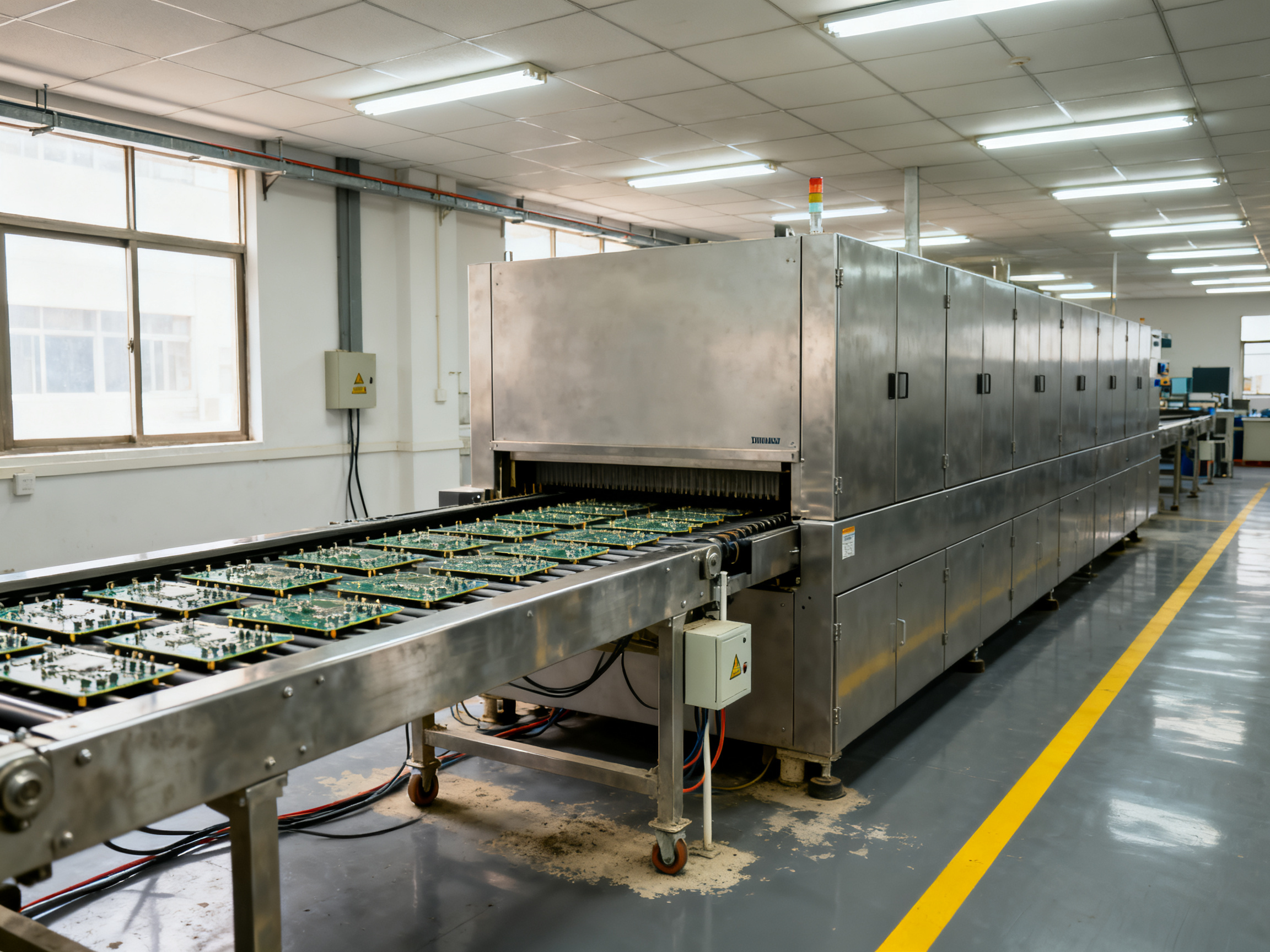
In this guide, we will explain how vacuum reflow works next to conventional reflow, where it helps, where it does not, how to set up an SMT vacuum reflow oven, how to build a vacuum reflow temperature profile, how to clean and calibrate the equipment, and how to compare vendors before you sign a purchase order. Ready? Let’s start with the science.
1. What Is Vacuum Reflow Soldering?
Here is the short version. Vacuum reflow soldering is a controlled soldering process that lowers the air pressure around the board while the solder is still molten. That reduced pressure gives trapped gas a path out. Without it, gas from flux and moisture stays locked inside the joint as voids.
The idea is not complicated. It is engineering.
A vacuum solder reflow oven adds four things to a normal reflow machine:
| System element | What it does |
| — | — |
| Heating zones | Bring the board up through soak and into the liquidus window, same job as any convection oven |
| Vacuum chamber or module | Pulls the chamber down to a set vacuum level and holds it while solder is liquid |
| Atmosphere control | Optional nitrogen or mixed gas around the board, which reduces oxidation and changes how flux behaves |
| Cooling zones | Drops the board temperature under control so joints freeze in a dense, predictable shape |
On top of that sit the sensors and controls: thermocouples for temperature, pressure transducers for the vacuum level, conveyor speed drives, oxygen sensors, and a recipe system that stores each profile.
Now the terminology, because this is where procurement conversations get messy. An SMT vacuum reflow oven usually means a standalone machine with its own vacuum chamber. A vacuum reflow soldering oven may be the same thing or a retrofit vacuum module bolted onto an existing conventional oven. A batch vacuum system pulls a drawer or cassette into an evacuated chamber. An inline vacuum system keeps the board moving on a conveyor while the working zone is under vacuum.
These are not equivalent. A batch machine and an inline machine with identical chamber vacuum will still differ in throughput, loading method, and how you load the oven.
Glossary
Pressure: How much the chamber pushes on the board, measured in pascals or millibars.
Absolute pressure: Total pressure measured against a perfect vacuum. 1013 mbar is sea level, so 100 mbar absolute is roughly 1/10th of an atmosphere.
Dwell time: How long the board sits inside the vacuum zone.
Voiding: Gas bubbles trapped inside a solidified solder joint.
Soak: A controlled heating phase that lets the whole board reach an even temperature.
Liquidus: The temperature where the solder alloy becomes fully liquid.
Peak temperature: The highest temperature the board sees.
Next up, we get into how vacuum reflow works next to a conventional oven, and where the two really part ways.
2. How Vacuum Reflow Works Compared With Conventional Reflow
Both processes start in the same place. Paste gets printed through a stencil, components get picked and placed, and the board travels into the oven. From there, the paths diverge, but only for about 90 seconds.
Here is the shared sequence, stage by stage.
| Stage | What happens in both processes |
| — | — |
| Printing and placement | Stencil deposits solder paste; the placement machine sets components on the pads |
| Preheat | Gentle ramp so solvents in the paste can dry without boiling |
| Soak | Temperature equalizes across the whole board so every joint reaches liquidus at the same time |
| Reflow (liquidus) | Alloy fully melts and wets the pad and the component terminal |
| Cooling | Joints solidify in a controlled way, usually with a defined cool-down rate |
| Inspection | AOI, then X-ray on hidden joints |
In a conventional oven, that is the whole story. Heat does the work, gas escapes upward or to the edges of the joint as it cools, and whatever is left behind stays in the solder.
In a vacuum reflow process, one extra stage is inserted right at the peak. The chamber pressure drops while the solder is fully molten. Trapped gas expands as the pressure falls, and because the solder is still liquid, the gas has somewhere to go. It bubbles out. The joint freezes denser.
Timing is the whole game here. Apply vacuum too early and the paste has not fully melted, so you pull air out of a joint that has not formed yet, which does nothing for the final void. Apply it too late and the solder has already solidified around the trapped gas, so the vacuum has no liquid to work with. The useful window is usually somewhere around liquidus plus a short soak inside the liquidus region, and the exact window depends on your alloy, your pad design, and your component mass.
Expert Tip: Vacuum timing and pressure ramp are not separate settings you dial in after profiling. They are part of the thermal profile. A ramp that is too steep can drag solder with the gas as it escapes, so tune pressure ramp, vacuum dwell, and time above liquidus together on one instrumented board before you record any recipe.
Pressure reduction also changes the chemistry slightly. Lower absolute pressure lowers the boiling point of the flux residue and the moisture in it, so volatiles tend to leave earlier than they would in air. That is part of why voiding drops. But it is also why the atmosphere control system matters. Air gives you oxidation risk on the board surface, while nitrogen reduces that. Air works fine for many boards. Nitrogen works better on fine-pitch and where surface appearance matters. Getting this balance right, rather than just pulling harder vacuum, is where most process wins come from.
And here is the part that gets skipped in vendor conversations. The oven is only one variable. Voiding results also depend on paste chemistry and print deposit volume, pad and stencil design, component geometry and venting, board thermal mass, atmosphere, pressure level, dwell time, ramp rate, and cooling rate. A great oven with bad stencil apertures and an aggressive paste will still make voids. Change one thing at a time during trials, or you will not know which knob fixed the problem.
[Animation: pressure-versus-temperature overlay showing chamber pressure falling during the liquidus window, with gas bubbles escaping from a molten joint.]
Up next we look at the benefits and the trade-offs, so you can decide honestly whether the void reduction is worth the capital and cycle time.
3. Benefits and Trade-Offs of Vacuum Reflow
So is vacuum reflow worth it? That depends on what your boards are failing on. Here is the honest split.
What you gain
Lower voiding is the headline, and it is the one benefit with the cleanest evidence trail. Joints form while gas is still being pulled out, so the solder freezes denser. That denser joint conducts heat better, which matters when a BGA sits under a heat sink or a power module is bolted down. Fewer voids also mean more consistent joint shape, so you get the same fillet geometry across a run instead of a spread of void patterns from board to board.
That consistency usually shows up as less rework. Rework on a hidden BGA joint is slow, and it carries its own risk of pad or solder damage. Cut rework, and you cut both labor and the scrap that follows it.
| Claim | How to verify it before you believe it |
| — | — |
| Lower voiding | X-ray void area percentage on a defined sample size, same recipe, before and after |
| Better thermal transfer | Joint-to-joint thermal resistance or impedance comparison, not a datasheet guess |
| More consistent joints | Process spread (Cpk) on void area across a qualification run |
| Less rework | Rework and scrap counts per 1,000 boards, tracked over a set window |
| Longer life | Accelerated thermal cycling or power cycling results, with sample counts stated |
What you pay
Capital is the obvious one. An inline vacuum reflow system costs more than a comparable convection oven, and a retrofit vacuum module still needs installation, sealing, and a new control layer. Then there are the running costs: nitrogen if you run an inert atmosphere, pump maintenance, chamber cleaning, seal replacement, and the extra floor space the chamber needs.
Cycle time is the sneakier cost. Adding a vacuum stage usually extends the reflow cycle, and on a high-takt line that is real money. A plant running three shifts at 85% OEE will feel a 15% cycle-time increase more than a plant running two shifts a week.
Then there is process development. Every board family needs its own profile, and vacuum adds variables the conventional oven did not have. Budget engineering time, not just machine time.
Expert Tip: Before you request quotations, write down three numbers: your current voiding level with its measurement method, your rework and scrap rate per 1,000 boards, and your takt requirement. Vendors quote against requirements, and without those three numbers every machine looks the same.
A realistic case
Take a typical automotive controller with a lead-free SAC305 assembly, a 0.5 mm-pitch BGA, and an exposed-pad QFN power section. The conventional oven gave a mean void area of 8 to 11 percent on the BGA balls, and the line was rejecting roughly 1.5 percent of boards at final test for open or weak joints under the QFN.
After switching to a vacuum reflow profile with the chamber pulled down during the liquidus dwell, the same paste and the same stencil produced a mean void area of 2 to 4 percent on the BGA. Final-test rejects on the QFN section dropped to under 0.2 percent. Rework time on the BGA fell by about 70 percent because fewer boards needed the hot air rework station.
Cycle time went the other way. It lengthened by roughly 20 percent, and the plant absorbed that by reducing conveyor speed on two lower-mix product families rather than adding a second oven.
The point is not that 8 percent to 2 percent is a promise. It is not. The point is that the numbers moved in a direction your X-ray report can confirm on your own product, and the cost side was visible and finite.
Where the marketing hides
Be skeptical of void-reduction claims that quote a single percentage with no test conditions. Ask for the alloy, the paste, the stencil aperture and paste deposit volume, the pressure level, the dwell time, the board type, the sample size, and the measurement method. A claim of 90 percent reduction means nothing without those details. Legitimate studies will give them to you. Vague ones will not.
Same with throughput claims. Ask for the board size the number applies to. Vacuum systems often quote their fastest cycle on a small single-board carrier, and real mixed-product lines carry larger panels with more thermal mass.
The trade is usually clear for BGAs, QFNs and bottom-terminated components, power modules, and anything under a mechanical clamp or heat sink. It is usually not clear for simple through-hole-plus-signal boards where the conventional oven already meets your own criteria.
Next, we get to the part most people actually need, which is deciding when a vacuum reflow oven is the right purchase and when it is overkill.
4. When Manufacturers Should Choose Vacuum Reflow
Here is the honest version. Vacuum reflow earns its capital when the joint is doing something hard, like carrying heat, current, or a mechanical load for ten years in a hot car or a vibration-heavy aircraft. It does not earn its capital on a board where the conventional oven already clears your own acceptance criteria.
Strong fit
These applications justify the investment without much argument:
| Application | Why vacuum helps |
| — | — |
| Automotive control modules | Constant thermal cycling and vibration punish weak, void-heavy joints |
| Aerospace and military electronics | Long field life, harsh environments, tight traceability demands |
| Power devices and power modules | Large thermal pads need full solder contact to move heat |
| BGA and bottom-terminated components | Hidden joints that X-ray cannot be repaired easily downstream |
| Semiconductor packaging and substrates | Fine-pitch, small die, zero-defect tolerance |
| High-reliability medical and industrial electronics | Warranty cost of one field failure dwarfs the oven |
| Advanced consumer devices | Thin form factors squeeze thermal paths on every board |
Also worth adding: anything that gets clamped, potted, or bolted down. Mechanical clamping after reflow can crack a joint that looks fine, and a denser joint resists that better.
Where conventional reflow still wins
Optimized conventional reflow is often enough when voiding specs are loose, the mix is simple, takt time rules the budget, and the line is space constrained. Think consumer accessories, simple two-layer boards with a handful of passives, and prototypes. If your X-ray data already shows joints inside spec and your field returns are flat, buying a vacuum chamber is solving a problem you do not have.
Pro Insight: Before you request quotations, write down three numbers: your current voiding level with its measurement method, your rework and scrap rate per 1,000 boards, and your takt requirement. Vendors quote against requirements, and without those three numbers every machine looks the same.
A qualification framework
Run this decision tree in order, and stop at the first yes.
- Do you have a documented defect or reliability target tied to voids? If no, there is no project yet.
- Does your package mix include BGAs, QFNs, BTCs, power modules, or exposed thermal pads? If no, conventional reflow is likely sufficient.
- Can you absorb the extra cycle time and floor space? If no, check a batch vacuum system instead of an inline one.
- Do you need traceable, repeatable profiles plus IPC-style process control and machine data export? If yes, that is a real argument for a modern inline system.
- Will volume or package mix grow over the next three years? If yes, buy for the future mix.
Then score the candidate machines against seven criteria: joint quality evidence, takt and cycle time, uptime and OEE, footprint and utilities, maintenance labor and consumables, data traceability and factory interfaces, and lifetime cost.
The honest summary: if your defect mode is voiding, if the package mix is dense, and if the field cost of failure is high, vacuum reflow usually wins on total cost. If none of those apply, a well-tuned convection oven is cheaper and faster, and that is fine.
Next, we walk through the actual mechanics of a vacuum reflow oven setup and how it drops into an existing line.
6. Cleaning, Calibration, and Preventive Maintenance
A vacuum reflow oven can hold a stable process profile for years, but only if the chamber, heaters, pumps, sensors, and carriers are maintained on schedule. Maintenance is not merely equipment uptime work: residue, sensor drift, pump performance, and conveyor alignment can all change solder joint quality before the recipe itself has changed.
The practical approach is to divide maintenance into three layers:
| Maintenance level | Typical frequency | Responsibility | Primary objective |
| — | — | — | — |
| Operator checks | Daily or per shift | Production operator | Catch visible damage, leaks, alarms, and loading problems early |
| Preventive maintenance | Weekly, monthly, and quarterly | Maintenance technician or vendor | Restore accuracy and prevent component failures |
| Annual calibration and service | Scheduled by usage and condition | Qualified service provider | Verify measurement accuracy and equipment condition |
Daily operator checks
Start each shift with a short visual and functional inspection before running production boards.
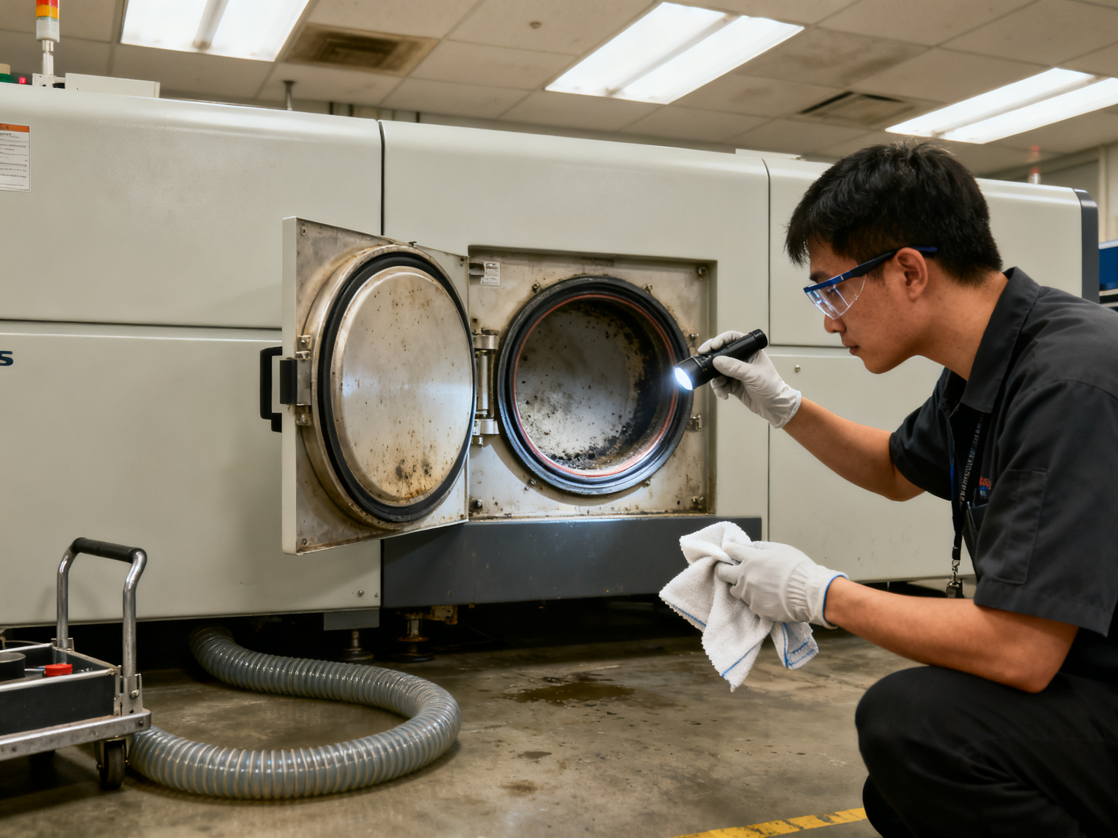
- Inspect the chamber and door seal. Look for solder splatter, flux residue, damaged sealing surfaces, debris around hinges, and visible moisture.
- Check the exhaust and condensate path. Confirm that exhaust flow is present and that condensate drains freely. A blocked drain can affect chamber pressure and create a slip hazard.
- Inspect the vacuum pump area. Listen for unusual noise, check for leaks at fittings, and confirm that oil level or pump condition is acceptable for the installed pump type.
- Check gas and utility connections. Verify that nitrogen or other process-gas regulators are in range and that hoses have not been kinked or damaged.
- Confirm sensor status. Review alarms for thermocouples, heaters, vacuum pressure, door position, and conveyor systems.
- Run a short empty cycle. Verify door operation, chamber evacuation, heating, conveyor motion, and cooling at the intended recipe settings.
- Check board-support hardware. Inspect carriers, rails, and transfer points for solder debris, bent parts, and accumulated contamination.
Record significant findings in the equipment log. Do not simply reset an alarm and continue without determining whether the underlying condition has changed.
Cleaning procedures
Chamber and heat-exchange surfaces
Flux residue and solder splatter should be removed before they become deposits that interfere with heat transfer or chamber sealing. Use the vacuum manufacturer’s approved cleaning method and cleaning agents. Avoid solvents, abrasive tools, and improvised materials that could damage seals, heaters, thermocouples, or insulation.
Before cleaning:
- Allow the oven to cool to the specified safe temperature.
- Isolate power and depressurize the chamber according to the equipment procedure.
- Remove boards, carriers, and loose debris.
- Photograph the chamber so heavy contamination and damage can be documented.
During cleaning, protect thermocouple leads and electrical connections. Do not strike the heating elements or scrape the chamber with metal tools. After reassembly, confirm that no cleaning fluid remains near high-temperature components.
Door seal and vacuum surfaces
Inspect the door seal regularly for flattening, cuts, contamination, and compression set. Clean both sealing surfaces with an approved agent. A seal that appears visually intact can still leak after chemical exposure or repeated thermal cycling.
Check that seal surfaces are not scratched and that the door closes evenly. If pressure cannot be held, inspect the seal before assuming that the pump is defective. An inexpensive seal test often prevents an unnecessary pump service call.
Exhaust, condensate, and pump systems
The exhaust route and condensate management are part of the process equipment, not facility afterthoughts. Clean or service accessible filters and drain lines on the interval specified by the manufacturer or based on measured restriction. Never disconnect an exhaust line while operating the pump without following the documented safe procedure.
For oil-lubricated pumps, monitor oil level, color, contamination, and temperature. Replace oil at the manufacturer’s specified interval and whenever moisture or metal particles are detected. For dry or diaphragm pumps, inspect the wear components on the recommended schedule. Do not operate a pump continuously with an abnormal sound, elevated temperature, or visible leak.
Conveyors and carriers
Vacuum reflow lines often carry solder debris through the oven on the bottom of the board or carrier. Remove buildup from rails, transfer mechanisms, and carrier surfaces using tools that will not damage the working surface. Check rail alignment and carrier latch operation while the line is locked out.
Replace damaged carriers rather than modifying them in the field. Changes to carrier geometry can affect heat transfer, board support, and indexing accuracy.
Calibration plan
Calibration should be tied to process risk and actual usage. A calendar-only schedule is ineffective if the oven has been idle for months or has been running heavy product continuously.
| Item | Typical verification | Frequency | Action when out of tolerance |
| — | — | — | — |
| Chamber thermocouples | Comparison with calibrated reference at operating temperature | Monthly or quarterly | Replace or recalibrate; update process-impact assessment |
| Heater output and zone control | Verify setpoint, overshoot, and repeatability | Quarterly | Correct control settings or replace heater |
| Vacuum sensor | Comparison with calibrated reference | Semiannual or annually | Replace or recalibrate |
| Door interlock and safety system | Functional test under the manufacturer’s procedure | Scheduled safety inspection | Repair immediately; do not bypass interlocks |
| Conveyor speed | Compare indicated speed with measured speed | Semiannual | Adjust drive or replace worn components |
| Exhaust flow and static pressure | Measure at the operating point | Semiannual or annually | Restore required capacity |
| Gas flow and regulation | Verify flow, pressure, and purity at use point | Quarterly or with cylinder changes | Correct regulator, leakage, or supply configuration |
| Recipe integrity | Compare stored recipe with approved master | After controller or firmware changes | Restore controlled master and repeat qualification |
Thermocouple calibration deserves special attention. A sensor can drift gradually, causing the controller to compensate in the wrong direction. The result may be a profile that appears repeatable from one run to the next while no longer representing the intended thermal process.
When a sensor is replaced, record its identity, position, calibration result, and effective date. If the sensor was used in a production profile, determine whether affected boards require additional review.
Preventive maintenance schedule
A useful preventive maintenance plan follows actual condition rather than a generic checklist copied from another oven. The following interval is a starting point; the manufacturer, production volume, solder chemistry, and environmental conditions should modify it.
Weekly
- Inspect the door seal and chamber for contamination.
- Check condensate drainage and exhaust condition.
- Review alarms and trend vacuum pull-down or hold performance.
- Inspect the visible pump area for leaks or abnormal noise.
- Clean accessible chamber and conveyor debris.
Monthly
- Test all chamber heaters at low and normal operating conditions.
- Check thermocouple connections for signs of heating, corrosion, or loosening.
- Inspect conveyor chains, gears, bearings, and tension.
- Verify gas regulator performance and inspect hose condition.
- Review maintenance and alarm logs for recurring faults.
Quarterly
- Perform an instrumented thermal profile on representative product.
- Verify zone control accuracy against a reference probe.
- Inspect vacuum fittings, hoses, seals, and chamber penetrations for leaks.
- Service the vacuum pump according to the manufacturer’s schedule.
- Calibrate or verify the vacuum sensor.
- Verify door, guard, and interlock operation.
Semiannual or annual
- Conduct a full safety inspection.
- Validate conveyor speed, exhaust flow, and static pressure.
- Review the complete calibration record and identify drifting instruments.
- Perform a comprehensive chamber, heater, and insulation inspection.
- Review operational data for trends in pump load, heat-up time, pressure stability, or temperature overshoot.
- Update preventive maintenance tasks and spare-parts stock based on findings.
Condition-based maintenance and trending
Preventive schedules identify problems that occur on average. Condition-based maintenance uses actual machine behavior to identify failures before they become production stoppages.
Trend the following parameters whenever the controller or data system permits:\n
- Time required to reach the target vacuum.
- Vacuum pressure during soak and heating.
- Leak rate during a defined hold.
- Pump motor current or load.
- Chamber heat-up and cool-down time.
- Zone temperature deviation from setpoint.
- Conveyor speed error.
- Door cycle time.
- Number and type of alarms.
- Profile drift against an approved reference.
A slow increase in pump load may indicate contamination or a worn component. A gradual rise in leak rate often points to a seal, fitting, or chamber-surface issue. Increasing cool-down time can indicate fan, exhaust, or airflow problems. These trends are more valuable than a single pass-or-fail reading because they show deterioration over time.
Spare parts and documentation
Hold critical spares based on lead time and failure impact. Depending on the machine design, this may include door seals, heater elements, thermocouples, fan components, conveyor sensors, vacuum sensors, pump service parts, fuses, relays, and approved lubricants or seal materials.
Every service event should include:
- Date, technician, and equipment identifier.
- Operating hours or cycle count.
- Symptoms and alarm history.
- Inspection findings.
- Parts replaced, including part number and lot or serial number.
- Calibration readings before and after the work.
- Verification procedure and acceptance result.
- Recommendations for follow-up.
Keep the equipment manual, electrical drawings, pneumatic diagrams, software backups, approved recipes, calibration certificates, and risk-assessment records current. Recipe changes should be version-controlled and traceable to the operator, approver, and effective date.
Maintaining process performance after maintenance
Any maintenance that can affect thermal or vacuum performance should end with verification. Clean the chamber, replace a thermocouple, service the pump, or alter the exhaust route, and the previous profile may no longer be valid.
At minimum:
- Run the documented leak test.
- Perform a thermal profile on an instrumented board at production speed.
- Compare the result with the approved process window.
- Run representative product and inspect joints using the required X-ray or other quality method.
- Release the equipment only after the result is documented and accepted.
Experience note: Most void problems blamed on a new recipe are actually old maintenance problems. Keep the chamber clean, verify the seals, calibrate the sensors, and trend the vacuum system. If the machine is stable before the process starts, the recipe becomes easier to qualify and easier to hold.
With utilities planned, commissioning disciplined, line interfaces verified, and maintenance under control, the vacuum reflow oven becomes a repeatable process asset rather than the least understood machine on the SMT line.
6. Temperature, Vacuum, and Profile Development
Let’s clear up the biggest myth in this whole topic right now. There is no single SMT vacuum reflow temperature. Not one number you can copy into a recipe and reuse across the plant. Anyone selling you a “standard vacuum reflow temperature” is selling you a starting point, not an answer.
The real profile has to match three things at once: the solder paste and alloy you actually bought, the component package limits, and the thermal mass of the board you are running. Change the paste from a low-temperature alloy to SAC305 and the liquidus moves. Change a stiff six-layer board to a thin two-layer board and the soak behavior changes. So the number is always a conversation between the datasheets and your actual product.
Here are the variables you are tuning, and what each one controls:
| Profile variable | What it controls | Common failure when wrong |
| — | — | — |
| Ramp rate | Solvent drying before liquidus | Solder balling, spatter, skipped joints |
| Soak range and time | Even board temperature, flux activation | Cold joints, uneven wetting |
| Time above liquidus | Window for wetting and gas escape | Grinning voids, weak fillets |
| Peak temperature | Full melt of the alloy | Overheat damage, lifted pads |
| Vacuum pressure level | Gas expansion and bubble escape | Too weak: voids stay; too fast: solder disturbance |
| Vacuum dwell | How long gas has to leave | Voiding if pulled too early or too late |
| Pressure ramp rate | How gently gas escapes | Splatter, component shift, disturbed joints |
| Cooling rate | Joint shape and freeze-in | Warping, microcracks, lifted corners |
| Thermal uniformity | Zone-to-zone consistency | Profile drift across the panel |
Getting these to cooperate is where most trials fall apart, because people change four settings and then cannot tell which one fixed the joint. The SMT reflow oven process rewards patience.
Here is the method that holds up. Start from the paste supplier’s alloy window and the component manufacturer’s package limits. Then run an instrumented board, usually a sacrificial coupon with the same stackup and copper coverage as production, and log real temperature at multiple points. Adjust one variable at a time and write down what changed. Confirm results with X-ray void area measurements and, where the application demands it, reliability testing.
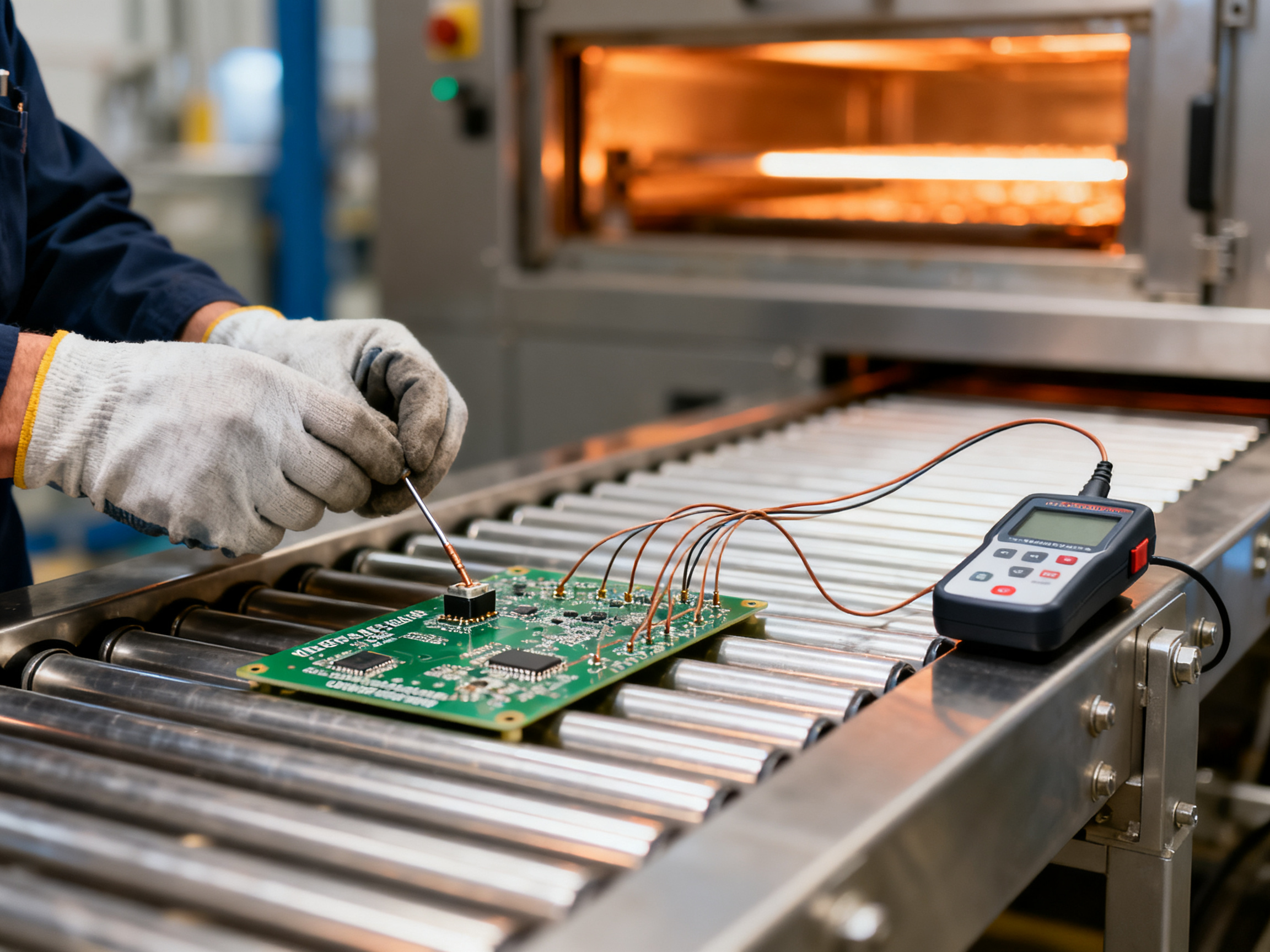
From Our Experience: On instrumented trial boards, the fastest way to cut voiding was rarely pulling harder vacuum. It was shifting the vacuum start a few seconds earlier inside the liquidus window, where the solder had fully melted but had not yet begun to skin over. Change one variable, take an X-ray of the same 20 joints each time, and the trend becomes obvious in two or three runs.
Some numbers to have ready when you start. Typical SAC305 profiles land near a 217°C liquidus, with peak temperatures usually in the 240 to 250°C range and total time above liquidus around 60 to 90 seconds, though your paste datasheet is the authority. If you need a starting point for the vacuum side, pull the chamber down into the low millibar range during the liquidus dwell and verify with a leak test before you trust a recipe.
Important: These are illustrative values for SAC305 with standard paste, not a universal specification. Always start from your own paste and package documentation.
Keep a parameter worksheet per product family: alloy, paste type, board stackup, zone setpoints, ramp, soak, peak, time above liquidus, vacuum level, dwell, cooling target, X-ray result, and the date of the last verification. When a profile drifts, that sheet tells you what was changed and what was supposed to happen.
And when you are ready to see how a vacuum solder reflow oven behaves on your line, ask for a trial protocol and an X-ray void measurement method before anything ships. A vacuum reflow soldering oven is only worth buying if the profile it holds is one you can prove.
Ready to talk it through? Send us your board mix, alloy, and current voiding numbers, and we will map them to a trial plan.
7. Cleaning, Calibration, and Preventive Maintenance
A vacuum reflow oven only holds a stable profile if the chamber, seals, pumps, and sensors stay clean and in tolerance. Residue on a heating surface, a drifting thermocouple, or a worn door seal will change your joints long before anyone touches the recipe. So maintenance is not housekeeping here. It is process control.
Cleaning targets
Follow the equipment maker’s approved agents and procedures. In general you are cleaning six areas:
- Chamber and heat-exchange surfaces. Flux residue and solder splatter reduce heat transfer and can compromise sealing.
- Door seal and sealing surfaces. Clean both faces; a seal can look fine and still leak after chemical exposure or thermal cycling.
- Condensate trap, drain path, and exhaust. Restriction here affects chamber pressure and floor safety.
- Conveyors, carriers, and rails. Debris rides along the oven bottom and shows up as thermal non-uniformity.
- Cooling zones and fans. Blocked airflow lengthens cool-down and distorts joint shape.
- Sensors and thermocouple wells. Residue on a thermocouple tip skews readings, which the controller then compensates for in the wrong direction.
Never scrape with metal tools near heaters or thermocouple leads, and never spray cleaner onto hot components.
Calibration and verification
Tie calibration intervals to actual usage and drift data, not the calendar alone. A machine idle for three months does not need a monthly thermocouple check.
| Item | Typical verification | Frequency |
| — | — | — |
| Chamber thermocouples | Comparison with a calibrated reference probe at operating temperature | Monthly to quarterly |
| Zone control | Setpoint, overshoot, and repeatability check | Quarterly |
| Pressure sensor | Comparison with a calibrated reference gauge | Semiannual |
| Conveyor speed | Indicated speed against measured speed | Semiannual |
| Oxygen and gas flow | Flow, pressure, and purity at the use point | Quarterly |
| Interlocks and alarms | Functional test per manufacturer procedure | Safety inspection cycle |
| Recipe integrity | Stored recipe against the approved master | After controller or firmware changes |
When you replace a sensor, record its identity, position, calibration result, and date. If it was carrying production profiles, review the boards run with it.
Frequency checklist
| Interval | Tasks |
| — | — |
| Daily | Inspect seal and chamber, confirm condensate drains, check for pump noise or leaks, review alarms, run one empty cycle |
| Weekly | Clean chamber and conveyor debris, test seal integrity, trend vacuum pull-down and hold time |
| Monthly | Test heaters, inspect thermocouple connections and gas hoses, check chain and gear tension, review fault logs |
| Quarterly | Instrumented thermal profile on representative product, leak check on fittings and chamber penetrations, pump service, vacuum sensor verification |
Troubleshooting table
| Symptom | Likely cause | First check |
| — | — | — |
| Voiding rises on a recipe that used to work | Residue buildup or thermocouple drift | Compare current profile against the approved master |
| Chamber will not hold vacuum | Door seal, fitting leak, or worn pump | Run a documented leak test before blaming the pump |
| Long cool-down times | Blocked cooling fan or restricted exhaust | Inspect airflow path and exhaust static pressure |
| Components shifting after reflow | Pressure ramp too steep or pull-down too fast | Reduce ramp rate and re-verify |
| Frequent seal-related alarms | Flattened or contaminated seal | Clean and inspect sealing faces |
From Our Experience: On trial boards, the fastest way to cut voiding was rarely pulling harder vacuum. Shifting the vacuum start a few seconds earlier inside the liquidus window, where the solder had fully melted but had not yet begun to skin over, did more. Change one variable, take an X-ray of the same 20 joints each time, and the trend shows up in two or three runs.
Expert Tip: Tie every maintenance task that can affect thermal or vacuum performance to a verification step. Clean the chamber, replace a thermocouple, service the pump, or reroute the exhaust, and the previous profile may no longer be valid. Run the leak test, re-profile on an instrumented board, compare against the approved process window, and release the equipment only after the result is documented.
Trend the pump load, leak rate, heat-up time, and profile drift over time. A slow rise in pump current or leak rate is a warning sign long before an alarm fires.
Ready to talk it through? Send us your board mix, alloy, and current voiding numbers, and we will map them to a trial plan.
8. Vacuum Reflow vs. Conventional Reflow Comparison
So here is the whole argument on one page. If you read nothing else, read this table.
| Factor | Conventional forced-convection reflow | Inline vacuum reflow system | Batch vacuum system |
| — | — | — | — |
| Joint quality | Good on simple joints, void-prone on BGAs and QFNs | Dense joints, low void area on hidden and bottom-terminated parts | Same joint quality as inline, processed in a drawer or cassette |
| Void control | None beyond atmosphere and profile tuning | Active gas removal during the liquidus window | Active gas removal during the liquidus window |
| Throughput | Highest, fastest cycle, smallest footprint | 10 to 25 percent longer cycle typical | Lowest, batch handling limits flow |
| Process complexity | Low, one recipe per product family | Moderate, pressure, dwell, and ramp join the recipe | Moderate, plus loading and unloading discipline |
| Maintenance | Oven basics only | Adds pump service, seal replacement, chamber cleaning | Adds the same, plus carrier and drawer service |
| Utilities | Electricity and exhaust, nitrogen optional | Adds nitrogen for inert atmosphere, stronger exhaust, more power | Adds nitrogen and chamber volume for evacuation |
| Footprint | Smallest | Larger, chamber needs clearance and service access | Largest per unit of throughput |
| Line integration | Drop-in on most lines | Requires line re-layout, interlocks, conveyor handshake | Standalone station, often off-line |
| Capital cost | Lowest | Highest | High |
| Best fit | Prototypes, simple mixed boards, tight takt | High-reliability, dense packaging, long field life | Low volume, high mix, short runs of critical boards |
A weighted scorecard your team can actually use
The table above tells you what is different. The scorecard below tells you what matters for your plant. Assign weights based on your own priorities, then score each option from 1 (poor) to 5 (strong).
| Criterion | Weight (example) | Conventional | Inline vacuum | Batch vacuum |
| — | — | — | — | — |
| Void and joint quality | 30 percent | 2 | 5 | 4 |
| Reliability and warranty risk | 20 percent | 2 | 5 | 4 |
| Takt time and throughput | 20 percent | 5 | 3 | 2 |
| Total cost of ownership | 15 percent | 5 | 2 | 2 |
| Future capacity and mix change | 10 percent | 3 | 4 | 3 |
| Maintenance load | 5 percent | 5 | 2 | 2 |
Weighted score equals weight multiplied by score, summed across all rows. Change the weights and you get a different answer, which is exactly the point. A plant chasing a defense contract weights reliability far higher than a plant chasing unit cost.
Vendor evaluation checklist
Before comparing quotes, put every vendor on the same page with these questions.
- What vacuum level is the machine rated for, measured in absolute pressure, and at what chamber volume?
- What is the verified dwell window inside the liquidus region, and how is it synchronized with the thermal profile?
- What board sizes, panel formats, and conveyor widths are supported at rated throughput?
- Which process atmospheres are supported, and what flow or consumption does each need?
- What leak rate does the chamber hold, and how is the leak test documented?
- Which factory interfaces are implemented, such as SMEMA, IPC-HERMES-9852, IPC-CFX, or MES links?
- What profile storage, recipe version control, and data export comes as standard?
- What are the FAT, SAT, installation qualification, and board trial acceptance criteria?
- What spare parts ship with the machine, and what is the lead time on the rest?
- Who performs calibration and service, and where are the calibration certificates held?
Ask for answers in writing. A vendor that answers question 3 with a cycle time measured on a single small carrier has told you exactly what you need to know about their other numbers.
Three scenarios, three different next steps
Scenario one: stay with conventional reflow. Your X-ray data shows joints inside your own acceptance limits, your field returns are flat, and takt time rules the budget. Buy the best convection oven you can afford and put the money into process development, atmosphere control, and stencil and paste optimization. Often this is the right answer, and nobody loses sleep.
Scenario two: add a vacuum module or system. You have a documented void defect, a dense package mix, and a high cost of field failure. Proceed with a full inline system, budget for the cycle-time hit, and treat utilities, floor space, and maintenance labor as part of the purchase price.
Scenario three: run qualification trials first. You are not sure the defect is the oven’s fault, or you want numbers before capital. Put a vacuum trial on one product family, measure the same joints before and after with the same X-ray method, and let the data make the call. This is the cheapest way to be wrong.
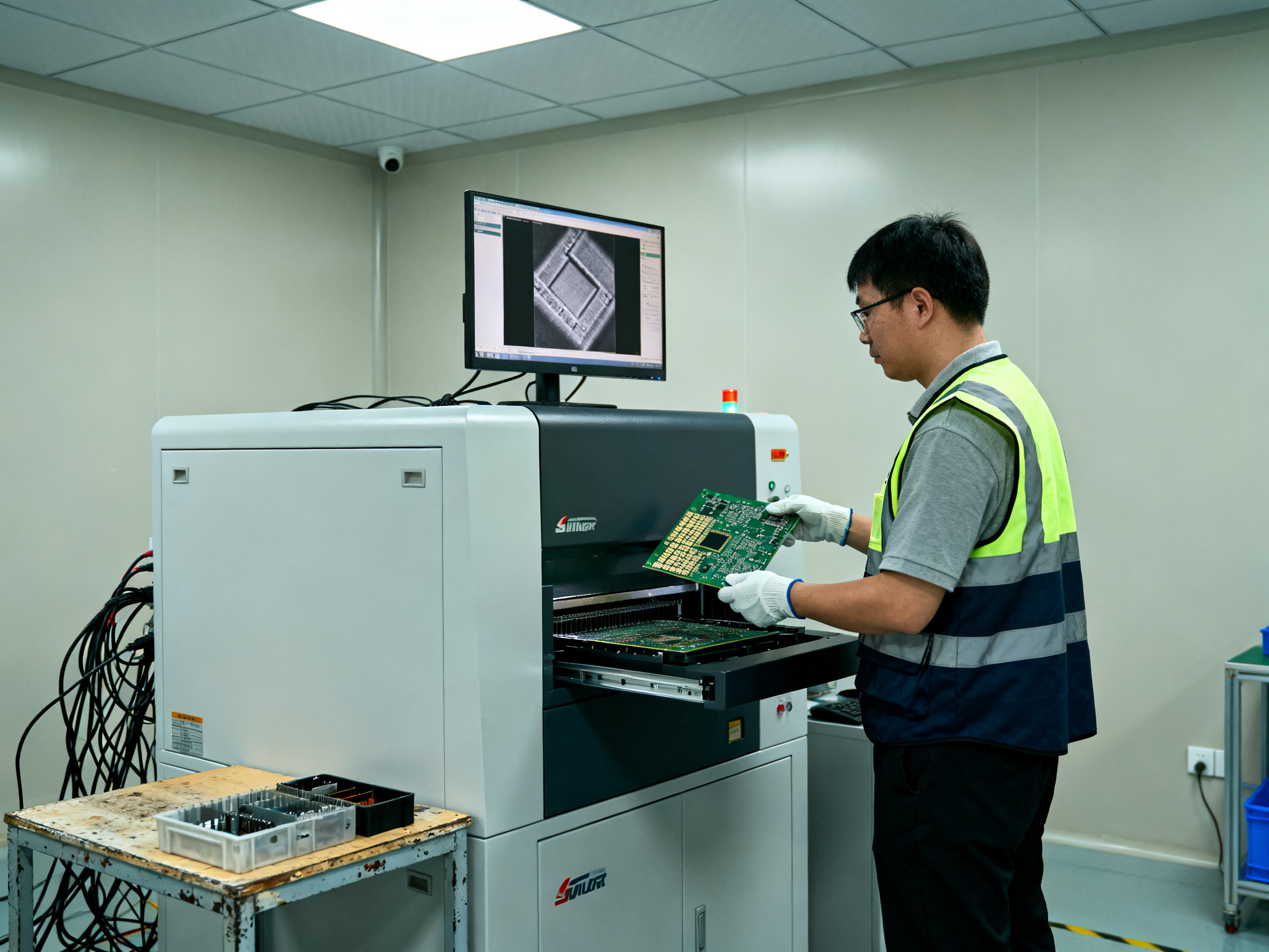
Honestly? Scenario three is the one I would pick. It costs a trial and a few days of engineering time, and it turns the decision into evidence instead of opinion.
If you want help structuring that trial, send us your board mix, alloy, current voiding numbers, and takt requirement. We will map them to a qualification protocol before anyone talks about equipment.
Conclusion: Build the Business Case Around Verified Defect Reduction
Vacuum reflow soldering is not a universal upgrade. It earns its place when a joint carries heat, current, or mechanical load for years, and when your X-ray data shows voids inside packages you cannot easily rework. On a simple mixed-product line where a well-tuned convection oven already meets your own acceptance limits, the extra capital, cycle time, and maintenance buy you very little.
If voiding is your defect mode, build the business case from your own numbers, not a supplier’s slide.
Five steps to a defensible decision
- Set the acceptance metric first. Write down the void area limit, the joint types it covers, the X-ray method, and the sample size.
- Pick representative boards. Include one worst-case assembly, a BGA or exposed-pad QFN, and one easy board so you can separate oven effects from design effects.
- Run a controlled trial. Profile the SMT reflow oven process first, then the vacuum process, changing one variable at a time and imaging the same joints each run.
- Compare the full cost set. Yield, rework, scrap, takt time, OEE, nitrogen, power, maintenance labor, floor space, and ownership cost, not sticker price.
- Size the system from the results. Inline vacuum for dense packaging and long field life. Batch vacuum for low volume, high mix, and critical short runs.
Next step: Send us your board mix, alloy, current voiding figures, and takt requirement. We will map them to a documented profile and X-ray trial protocol, then help you specify the right vacuum reflow oven setup. Review our vacuum reflow oven specification checklist before you request quotations.