
Published: 25 May 2026
Reading Time: 10 minutes
Reviewer: Simon Scrapes, Founder
Introduction: Importance of Reflow Oven Temperature Profiles in SMT Manufacturing
Think about the last time you pulled a perfectly assembled smartphone from its packaging. All those tiny components, all those microscopic solder joints holding everything together. Now imagine the factory floor where that device was born. Somewhere in that production line sat a reflow oven, and that oven had one job: heat your board to exactly the right temperature, at exactly the right speed, for exactly the right amount of time.
Sounds simple, right? It is not.
SMT manufacturing throws some serious curveballs at precision soldering. You’ve got dozens of components on a single board, each with different thermal mass and heat sensitivity. You’ve got lead-free solders that need higher temperatures than the old stuff. And you’ve got manufacturers pushing for faster throughput without sacrificing quality. Oh, and did I mention that some components can crack if they heat up too quickly?
This is where reflow oven temperature profiles step in to save the day.
A temperature profile is basically a roadmap for how heat moves across your PCB during soldering. It controls the preheat ramp rate, the soak time, the peak temperature, and how fast your board cools down. Get any of these wrong and you could end up with cold joints, tombstoning, or components that are straight-up damaged.
But get it right, and you get uniform, reliable solder joints across thousands of boards.
So here is the deal with this guide. We are going to walk through everything you need to know about reflow oven zones and temperature cycles, the key factors that influence your profile, and the best practices for keeping thermal management tight. Whether you are running a high-volume line or just trying to reduce defects, this guide will help you dial in your process for better precision and efficiency.
Let’s get into it.
Understanding the Basics: Zones and Temperature Cycles in Reflow Ovens
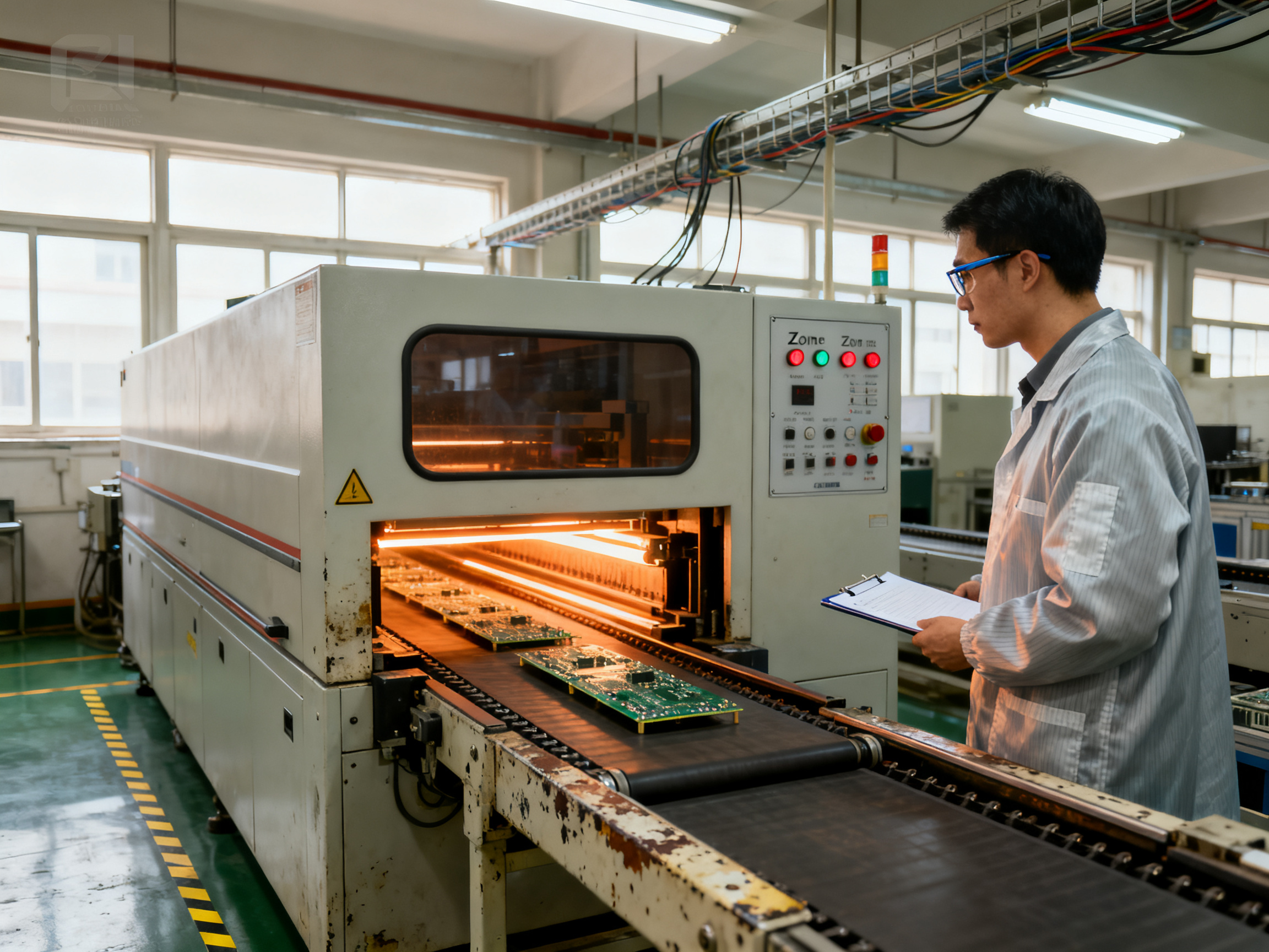
Think of a reflow oven like a carefully choreographed dance floor for your PCBs. The board enters one end and travels through different temperature zones, each one doing a specific job before the final solder joints form.
The Four Main Zones
Preheat Zone
This is where we gently warm up the board. The goal is to bring everything up to temperature slowly, so you avoid thermal shock to sensitive components. Most preheat zones run somewhere between 100°C and 150°C. The ramp rate here matters big time. Too fast and you risk cracking those delicate BGA components.
Soak Zone
Once the board hits that initial temperature, it enters the soak zone. Here the temperature levels off and heat spreads evenly across the entire board. This gives all those components with different thermal mass a chance to catch up with each other. Flux activation happens here too, which cleans the metal surfaces for better wetting.
Reflow Zone
This is the hot stuff. The reflow zone takes your board up to peak temperature, somewhere around 235°C to 250°C for lead-free solders. The solder paste melts and forms those microscopic joints that hold everything together. Time above liquidus (TAL) is the key metric here. Too short and the solder won’t flow right. Too long and you risk oxidation or component damage.
Cooling Zone
Finally, the board enters the cooling zone where it drops in temperature at a controlled rate. Controlled cooling helps prevent thermal stress and ensures the solder solidifies with the right grain structure. A good cooling rate is usually around 3°C to 4°C per second.
Zone Functions at a Glance
| Zone | Temperature Range | Primary Purpose |
|——|——————|——————|
| Preheat | 100°C to 150°C | Gradual warming, prevent thermal shock |
| Soak | 150°C to 180°C | Even heat distribution, flux activation |
| Reflow | 235°C to 250°C | Melt solder, form joints |
| Cooling | Down to room temp | Controlled solidification |
The whole dance usually takes 4 to 8 minutes, depending on your board complexity and the solder alloy you’re using. Some newer ovens in 2026 can run even faster with improved convection technology.
Expert Tip: Optimal temperature ranges vary by solder alloy and component sensitivity. Always verify your profile against your specific paste datasheet and make adjustments for boards with high thermal mass or heat-sensitive parts.
We’ve run into situations where skipping the soak zone to save time seemed like a good idea. Spoiler alert: it never is. Those rushed profiles always came back to haunt us with uneven solder joints and weird defects that were hard to trace.## Key Factors Influencing Reflow Oven Temperature Profiles
Here’s something most people don’t think about until things go sideways: not all solder is created equal, and that changes everything about how you run your oven reflow temperature settings.
Solder Alloy Type
The type of solder you’re working with fundamentally dictates your temperature window. Leaded solder melts around 183°C, which feels almost quaint compared to lead-free options that require 217°C to 250°C. This shift to lead-free wasn’t optional. RoHS regulations pushed the industry in that direction, and now we’re dealing with higher melting points, longer exposure times, and completely different thermal stress patterns on our boards.
Lead-free reflow temperature settings are trickier because the solder doesn’t flow as easily. You need more heat energy to get proper wetting, which means your profile has to push higher peak temperatures while still protecting sensitive components from damage.
PCB Material and Heat Sensitivity
Your board substrate plays a massive role in how your profile needs to be structured. Standard FR4 handles heat differently than polyimide or ceramic substrates. Ceramic boards, for instance, pull heat energy faster and require different thermal management approaches compared to standard materials.
Component heat sensitivity is another piece of the puzzle. Some parts can crack if they experience too fast a temperature ramp, while others are more forgiving. You need to know what you’re working with before you start tweaking zone temperatures.
Component Density and Assembly Layout
This is where things get really interesting. How hot do reflow ovens get, you ask? It depends on what you’re putting inside them. High-density boards with lots of BGAs and QFNs create thermal mass variation across the board. Large components act like heat sinks, absorbing energy and slowing down the heating rate. Small resistors and capacitors? They heat up fast and can easily overshoot if your profile isn’t balanced.
We’ve tested boards where the thermal mass variation was so extreme that one corner was 15°C cooler than the other during reflow. Fixing that meant restructuring our preheat ramp and extending soak times. That’s the kind of thing you only discover through proper thermal profiling, not guesswork.
Pro Insight: Customizing profiles for different alloy compositions requires matching time above liquidus to your specific paste. Lead-free pastes often need higher peak temperatures and longer exposure times compared to traditional tin-lead formulations.
Board layout matters too. Dense areas with lots of components need more preheat time to bring everything to temperature evenly. Boards with heat sinks or heavy ground planes will pull energy differently than sparse layouts. Both scenarios need attention, just different kinds.
The good news? Modern reflow ovens in 2026 have better convection and airflow control than ever before, which helps with uniformity. But even the best equipment needs a properly tuned profile to deliver consistent results. If you’re running lead-free reflow temperature settings without profiling your specific board, you’re basically guessing. And guessing in production usually means defects.
Take it from us. We learned this the hard way. A few extra minutes profiling a new board design saves hours of rework later.## Best Practices for Thermal Management in Reflow Soldering
Thermal management is where theory meets reality in SMT production. You can have the perfect profile on paper, but if your oven has hot spots or your board layout creates temperature gradients, you’re going to see defects. Here’s what actually works in 2026 for keeping thermal processes tight.
Strategies for Even Heat Distribution
The number one enemy of consistent solder joints is uneven heating. Hot spots in your oven create temperature swings across the board, and cold spots do the same thing in reverse. Both scenarios lead to unpredictable joint quality.
Convection technology has gotten way better in recent years. Forced hot air reflow ovens with multi-point airflow control give you much more uniform temperature distribution compared to older radiant heating designs. If you’re still running legacy equipment, this is probably the single biggest upgrade you could make to your thermal management capability.
Conveyor speed consistency matters more than most people realize. Any variation in belt speed creates areas where boards spend more or less time in each zone. Check your conveyor alignment regularly. We’ve seen production issues traced back to a conveyor belt that was slipping slightly under load.
Board support fixtures can help with warpage on thin panels, but they also affect heat transfer. Metal fixtures conduct heat away from your board, which means areas in contact with the fixture heat up slower than exposed regions. Factor this into your profiling if you’re using fixtures.
From Our Experience: We’ve dealt with thermal inconsistencies that led to frustrating defect patterns. One time, a batch of boards kept showing intermittent joint failures on one side. Turns out the oven airflow was partially blocked by old solder residue. A thorough cleaning fixed everything. The lesson? Even small obstructions disrupt airflow patterns and create temperature gradients you can’t see until defects start appearing.
Protecting Delicate Components
Some components just can’t handle the heat. QFNs with exposed pads, moisture-sensitive BGAs, and small chip components with fine pitch leads are all vulnerable to thermal damage if your profile isn’t dialed in.
For moisture-sensitive devices, make sure your preheat ramp stays gentle enough to drive out moisture without causing delamination. The IPC/JEDEC standards specify maximum ramp rates for these parts, and they exist for good reasons. Don’t skip the datasheet review on any component you haven’t worked with before.
Component placement on the board affects thermal exposure too. Large connectors or heatsink components shade the board beneath them. You can compensate with targeted preheat adjustments or strategic placement of thermocouples during profiling to capture these shadowed areas.
BGA components need special attention because the solder balls underneath the package are hidden from view. If a BGA bridge or opens, you won’t see it without X-ray inspection. This means your profile absolutely must be verified with thermal profiling that includes measurements directly under large BGAs. Guessing here is not an option.
Monitoring and Adjustment During Production
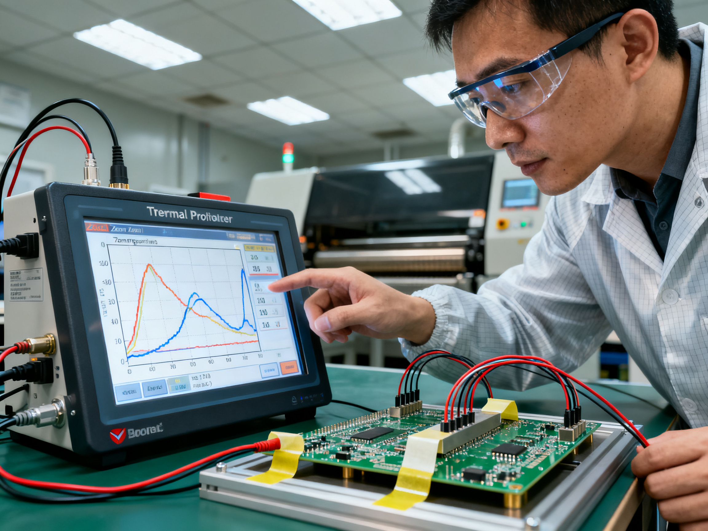
Profile verification isn’t a one-time thing. Your oven changes over time. Heating elements age, fans wear out, and airflow patterns shift as equipment accumulates residue. Regular thermal profiling catches these drift issues before they create defects.
In 2026, many manufacturers are using continuous monitoring systems that track real-time temperature data during production runs. This gives you immediate feedback if something drifts out of spec. For high-volume operations running the same board repeatedly, this investment usually pays for itself quickly in reduced rework costs.
That said, you don’t need fancy systems for effective monitoring. Even basic thermocouple-based profiling done weekly or with every major product changeover keeps you in control of your thermal process. The key is making it routine, not reactive.
When something does go wrong, having good process records makes troubleshooting way faster. Log your profiles, track defect rates by shift or lot, and correlate changes. Most thermal issues leave patterns that become obvious when you have the data.
Thermal Management Checklist
Use this checklist to reduce inefficiencies in your reflow process:
- [ ] Verify oven temperature uniformity with thermal profiling every production shift
- [ ] Clean airflow channels and heating elements weekly
- [ ] Check conveyor speed and alignment monthly
- [ ] Review component datasheets for thermal restrictions before running new products
- [ ] Monitor humidity levels in the production environment
- [ ] Keep detailed logs of profile settings and defect rates
- [ ] Calibrate thermocouples and profilers against known standards
- [ ] Inspect boards for warpage that might affect heat transfer
Thermal management isn’t glamorous work. It’s the unglamorous foundation that lets everything else in your SMT line perform reliably. Get these basics right, and you’ll spend way less time firefighting defects and way more time making good boards.## Advanced Considerations: Reflow Oven BTU Ratings and Lead-Free Compliance
If you have been shopping for a new reflow oven lately, you have probably seen BTU ratings thrown around in spec sheets. BTU stands for British Thermal Unit, and it measures how much heat energy an oven can deliver. But here is the thing that trips up a lot of buyers: higher BTU does not automatically mean better performance for your application.
Understanding Reflow Oven BTU Ratings
BTU ratings tell you the total heating capacity of your oven across all zones combined. A small benchtop unit might put out 5,000 to 10,000 BTU per hour. A mid-size production oven typically runs 30,000 to 60,000 BTU. Large industrial units can exceed 100,000 BTU when you factor in multiple heating zones and high-speed convection fans.
What actually matters is whether that BTU capacity can maintain stable temperatures under your actual production load. An oven rated at 50,000 BTU might struggle if you are running thick aluminum-core boards that absorb heat like crazy. The same oven would cruise through thin FR4 panels with no problem.
So how do you match BTU capacity to your needs? Here is a practical breakdown based on production scale and solder type.
| Production Scale | Typical Board Size | Lead-Free Solder BTU/hr | Leaded Solder BTU/hr |
|——————-|——————-|————————|———————-|
| Prototype/Low Volume | Up to 300mm | 15,000 – 25,000 | 10,000 – 18,000 |
| Medium Volume | 300mm – 500mm | 25,000 – 50,000 | 18,000 – 35,000 |
| High Volume | Over 500mm | 50,000 – 100,000+ | 35,000 – 70,000 |
These ranges assume forced convection technology. Older radiant-style ovens need significantly more BTU to achieve the same thermal uniformity.
Manufacturers like S&M Co. Ltd. design their lead-free reflow ovens specifically to deliver high thermal output efficiently. Their systems target the 235°C to 250°C peak temperatures that lead-free alloys demand, while still maintaining the precise temperature gradients needed for quality solder joints.
Adjusting Profiles for Lead-Free Compliance
Switching to lead-free solder is not optional anymore if you are selling products in major markets. RoHS compliance requires it, and the thermal implications ripple through your entire process.
Lead-free reflow temperature settings typically run 20°C to 40°C higher than their leaded counterparts. This sounds simple, but that extra heat creates real problems if you do not compensate. Higher peak temperatures accelerate oxidation on your solder paste and your board surfaces. Flux becomes less effective at those temperatures, so your preheat and soak phases need adjustment to give flux activation enough time to work.
Component stress increases too. Those delicate BGAs and QFNs you have been using? They are now experiencing more thermal load than they would with leaded solder. Your preheat ramp rates might need to slow down, especially for moisture-sensitive components. Some manufacturers run separate profiles for leaded and lead-free products specifically to manage this.
From Our Experience: We once tried to run a lead-free profile at the same temperatures we used for tin-lead solder. The joints looked fine on the surface, but X-ray inspection revealed significant voiding underneath BGAs. The flux was burning off before proper wetting happened. Dropping the peak temperature by 10°C and extending our soak time fixed it completely.
Balancing Energy Efficiency with Soldering Reliability
Here is the tension that keeps production managers up at night. You want to run your oven efficiently, which usually means higher conveyor speeds and shorter cycle times. But push too hard and you sacrifice the thermal precision that prevents defects.
Modern reflow ovens in 2026 are much better at this balancing act. Improved insulation, smarter zone control, and advanced convection systems let you achieve faster throughput without cranking up the heat or extending exposure times. Ovens with closed-loop temperature control adjust power to each zone dynamically based on actual thermal readings, not just setpoints.
Energy recovery systems are another development worth watching. Some newer ovens capture waste heat from the cooling zone and redirect it toward preheating, which reduces total energy consumption significantly. For high-volume operations running 24/7, this adds up fast.
The practical takeaway? Do not cheap out on oven capacity. An underpowered unit will fight you every day, running hot continuously and still struggling to maintain uniformity. Right-sized BTU capacity gives you headroom for process optimization without compromising reliability.
When you are evaluating equipment, ask vendors for thermal profiling data under load. Any reputable manufacturer should be able to show you actual measurements proving their oven meets specifications. If they cannot or will not provide that, keep shopping.## Choosing and Calibrating Reflow Ovens for Optimal Results
So you are ready to invest in a reflow oven. Maybe your old unit is showing its age, or you are scaling up operations and need more capacity. Either way, asking the right questions before you buy saves headaches down the road.
Questions to Ask When Evaluating Reflow Ovens
First, think about your actual production needs. What board sizes are you running? How many zones do you actually need? Most production ovens offer 4 to 8 zones, but smaller operations can get by with less. Overspending on zones you will never use does not make sense.
Ask vendors about temperature uniformity across the oven width and length. A unit might hit your target peak temperature, but if hot spots exist, your boards will cook unevenly. Request thermal profiling data from actual production runs, not just marketing specs. Any manufacturer worth their salt can show you real measurements proving their equipment performs.
Consider your solder type too. If you are running lead-free, and you probably are, make sure the oven is rated for those higher reflow oven temperatures. S&M Co. Ltd. designs their lead-free reflow ovens specifically for the 235°C to 250°C range that modern alloys demand. Their equipment handles the increased thermal load without struggling to maintain stability.
Calibration Procedures for Consistent Performance
Buying good equipment is only half the battle. Keeping it calibrated is what actually delivers results day after day.
Start with conveyor speed verification. Use a calibrated speed checker to confirm your actual belt speed matches your settings. Even small deviations compound over thousands of boards.
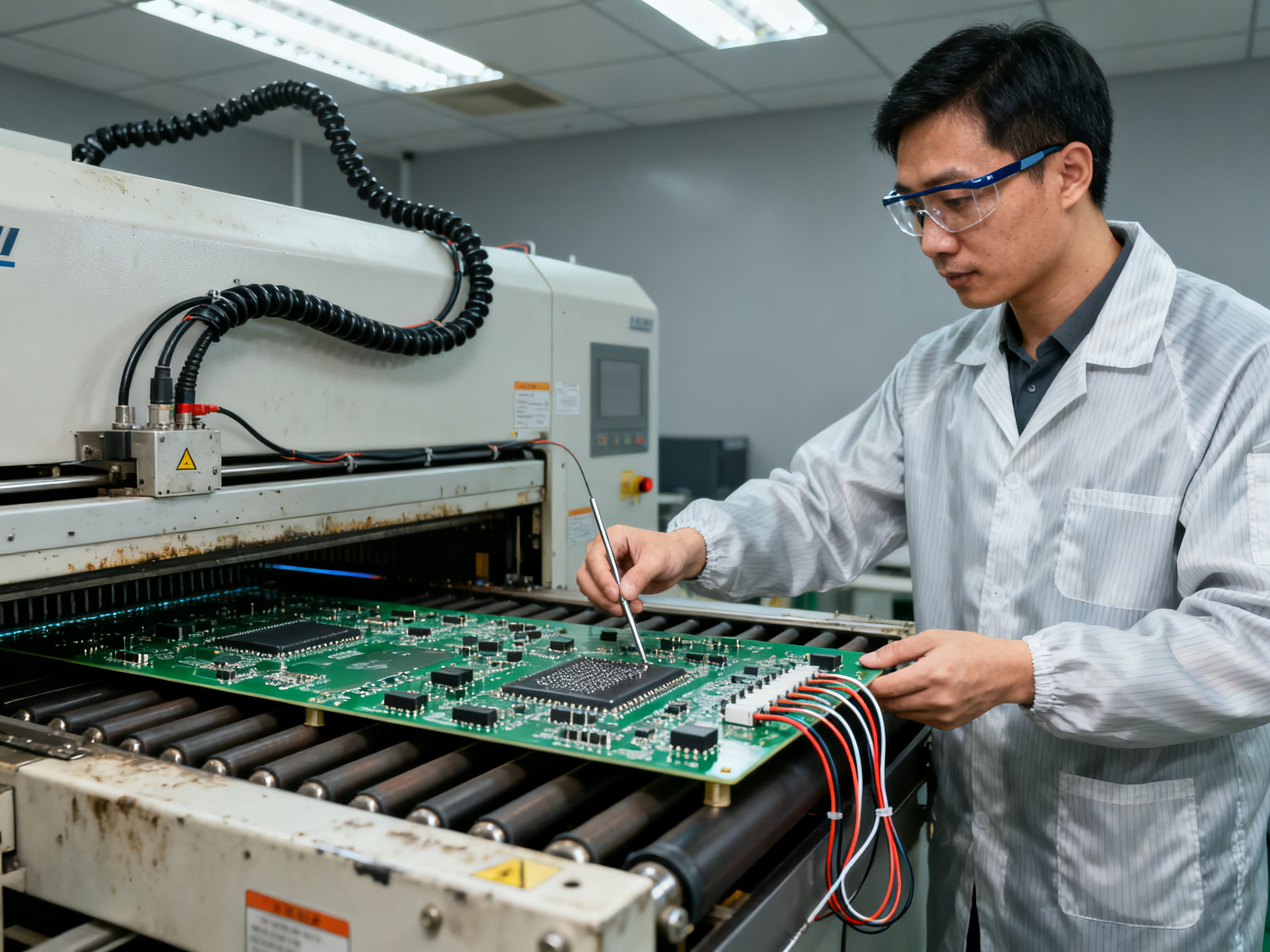
Next, run thermal profiling with thermocouples attached to a test board. Measure actual board temperature, not just oven air temperature. These two things can differ significantly depending on board mass and airflow patterns. Compare your readings against your target solder paste specifications for preheat ramp rates, time above liquidus, and peak temperatures.
Make consistency checks part of your routine. Place test boards at different positions across the conveyor width to verify uniform zone operation. Most calibration drift happens gradually, which is why regular profiling catches issues before they create defects.
Monitoring Tools for Ongoing Validation
In 2026, manufacturers have better options for continuous monitoring than ever before. Closed-loop temperature control systems adjust power to each zone dynamically based on real-time readings. This keeps your reflow profile tight even as equipment conditions change over time.
Process records matter too. Log your profile settings, track defect rates, and correlate changes. When something goes wrong, good records make troubleshooting way faster.
The bottom line? Choose equipment that matches your real production needs, then stay on top of calibration. That combination is what separates manufacturers who fight constant defects from those who ship quality boards reliably, day after day.## Conclusion: Taking Reflow Oven Performance to the Next Level
So here we are. We have walked through the entire thermal journey of a PCB through a reflow oven, from that gentle preheat ramp all the way through to controlled cooling. If there is one thing I want you to take away from all this, it is that temperature profiling is not optional. It is the difference between boards that work and boards that fail.
Your reflow profile controls everything. The preheat ramp rate that keeps delicate BGAs from cracking. The soak time that gives flux activation enough room to do its job. The peak temperature that melts your solder without torching your components. And the cooling rate that sets your joint grain structure for long-term reliability.
Get these zones dialed in, and you reduce tombstoning, bridging, cold joints, and voiding. Your defect rates drop, your rework costs plummet, and your production line runs the way it is supposed to run.
Your Next Steps
Here is what I would do if I were sitting where you are sitting right now. First, grab a thermal profiler and actually measure what is happening on your production boards. Do not guess. Thermocouples and real data change everything. Second, match your profile to your paste datasheet. That document exists for a reason. Third, build a calibration routine that you follow religiously. Oven drift happens slowly, so regular checks catch problems before they become disasters.
The manufacturers winning in 2026 are the ones treating thermal management as a continuous improvement process, not a one-time setup task.
Key Takeaways at a Glance
| Aspect | What to Remember | Recommended Action |
|——–|—————–|——————-|
| Preheat Zone | Keep ramp rate gentle to prevent thermal shock | Target 1°C to 2°C per second |
| Soak Zone | Allows flux activation and heat equalization | 60 to 120 seconds typical duration |
| Reflow Zone | Peak temperature for solder melting | 235°C to 250°C for lead-free |
| Cooling Zone | Controlled solidification prevents stress | 3°C to 4°C per second cooling rate |
| Profile Customization | Different alloys need different profiles | Match to paste datasheet specifications |
| Calibration Routine | Ovens drift over time | Profile weekly or with major changeovers |
| Thermal Mass Variation | Large components create temperature gradients | Use fixtures and extend soak times as needed |
Whether you are running S&M Co. Ltd. equipment or any other reflow oven brand, the principles stay the same. Know your zones. Profile your boards. Maintain your equipment. The rest is just execution.
Now get out there and make some good boards.