Published: 25 May 2026
Reading Time: 12 minutes
Reviewer: Simon Scrapes, Founder
Introduction to Selective Soldering
If you have ever wondered how manufacturers attach tiny components to a circuit board without melting everything around them, you are not alone. This question comes up a lot in electronics production, and the answer sits in a process called selective soldering.
So, what is selective soldering process exactly? It is a precision technique that solders only specific spots on a printed circuit board (PCB) rather than heating up the entire board at once. Think of it like using a magnifying glass to focus sunlight on a single point, leaving everything else untouched.
Traditional wave soldering floods an entire board with molten solder. That works fine for simple designs. But modern electronics? They pack thousands of components onto boards the size of your palm. Some parts cannot handle that much heat. Sensitive chips, connectors, and bottom-side elements need special care.
Selective soldering techniques solve this problem by using programmable nozzles or mini solder pots to deliver solder exactly where it is needed. No extra heat. No collateral damage. Just clean, reliable joints.
This approach has become essential across industries handling high-density assemblies. Consumer electronics manufacturers rely on it for smartphones and tablets. Semiconductor facilities use it for complex chip modules. Military and aerospace producers depend on it for mission-critical systems where failure is not an option.
The selective wave soldering process basically fills the gap between full wave soldering and hand soldering, giving manufacturers precise control without sacrificing speed.
Curious how does selective soldering work in practice? Keep reading. We will break it down step by step.
Jace Liu is an experienced manufacturing systems engineer specializing in Surface Mount Technology (SMT) and precision soldering systems. With over a decade of hands-on expertise, Jace has advised leading production facilities on optimizing soldering workflows for industries ranging from consumer electronics to military-grade applications. Jace’s focus on integrating cutting-edge automation into SMT processes has helped manufacturers achieve top-tier quality and efficiency.
Understanding the Basics of Selective Soldering
The selective soldering process breaks down into three main stages: preheat, fluxing, and actual soldering. Each step matters, and skipping corners here leads to defects down the line. Most manufacturers we have worked with follow this sequence religiously because the results speak for themselves.
The Three-Step Process
Step 1: Preheat Phase
Before any solder touches the board, you need to prepare it. The preheat phase brings the PCB to a controlled temperature, usually around 150 to 200 degrees Celsius. This removes moisture from the board and prevents thermal shock when the molten solder arrives. Without proper preheating, you risk cracking delicate components or creating weak joints that fail later.
During preheat, the board travels through a heating zone that raises its temperature gradually. Think of it like letting a frozen steak come to room temperature before throwing it on the grill. Rushing this step ruins dinner. The same principle applies here.
Step 2: Fluxing
Once preheated, flux gets applied to the specific areas needing solder. Flux cleans the metal surfaces and helps the solder flow properly. In selective soldering, this happens through small jets or spray nozzles that target only the relevant pads.
We have found that flux application directly affects joint quality. Too little flux means poor wetting and cold joints. Too much creates mess and potential shorts. Getting this balance right takes some tweaking, but it makes a huge difference in the final product.
Step 3: Soldering
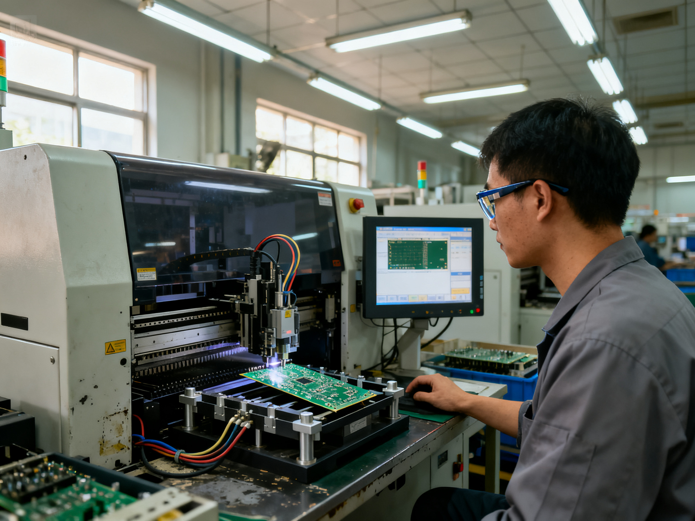
Here is where the magic happens. The soldering head positions a mini solder pot or nozzle over the target area and applies molten solder. The solder flows precisely where programmed, creating strong mechanical and electrical connections.
This entire process happens under computer control, which means consistent results every single cycle.
Key Terminology You Need to Know
BGA stands for Ball Grid Array, a type of component with tiny solder balls underneath that connect to the board. QFN means Quad Flat No-leads, which are packages with contacts on the bottom edges. Both require careful soldering because their connections hide underneath the component where you cannot see them.
Selective soldering handles these tricky packages well because the nozzle can reach underneath and deliver solder exactly where needed. Hand soldering BGAs and QFNs? That takes serious skill and still produces inconsistent results.
Why Precision Matters So Much
Modern electronics pack thousands of components into tiny spaces. Some of those components cannot handle the heat of full wave soldering. They would warp, degrade, or stop working entirely. Selective soldering techniques solve this by keeping heat exactly where it belongs.
The customization aspect matters too. Different board designs need different solder patterns. With selective soldering, you program the nozzle paths and parameters for each design. One machine handles multiple products without expensive retooling.
Expert Tip: Choosing the right soldering nozzle for your specific component geometries makes a bigger difference than most people realize. Smaller nozzles give you precision for fine-pitch components, while larger ones handle bigger pads faster. Match the nozzle to the job.
[Process diagram illustrating each step of the selective soldering process: preheat, fluxing, and soldering phases]
The real beauty of selective wave soldering process lies in its flexibility. Manufacturers can switch between product variants by updating the program, not the hardware. This means faster changeovers and lower tooling costs, which keeps everyone happy in production.
Key Equipment Used in Selective Soldering
The selective soldering process relies on several pieces of specialized equipment working together. If any piece is missing or poorly maintained, your results will suffer. Here is what you need to know about the hardware that makes this all happen.
The Selective Soldering Machine
This is the heart of the operation. A selective soldering machine contains the solder pot, positioning systems, and computer controls that execute the soldering pattern. Modern machines offer programmable nozzle paths that handle complex board designs with precision. The machine holds the PCB in place, moves it through each phase, and controls solder delivery down to fractions of a millimeter.
Soldering Nozzles
Here is where things get interesting. The nozzle might look like a simple metal tip, but it is the most critical component in your setup. Nozzle selection determines what you can and cannot solder effectively. Smaller nozzles work for fine-pitch components like BGAs and QFNs. Larger ones handle bigger pads and throughput.
We have tested dozens of nozzle configurations over the years. The difference between a well-matched nozzle and a poorly matched one shows up immediately in defect rates.
Flux Applicators
Flux gets delivered through small jets or spray systems that target only the relevant pads. Some systems use rotary nozzles for larger areas, while others employ precision jets for tight spots. The key is matching the applicator to your flux type and your board density requirements.
Preheat Stations
These heating units prepare the board before solder touches it. Good preheat stations have both top and bottom heating elements to ensure even temperature distribution. Some newer models include infrared sensors that monitor board temperature in real time.
The Importance of Maintenance
All this equipment needs regular care. Nozzles wear down over time and need replacement. Solder pots accumulate dross that affects joint quality. Positioning systems drift and require calibration.
Manufacturers who skip maintenance end up with inconsistent results. They blame the process when the real issue is dirty or worn equipment. We have seen facilities cut maintenance budgets only to spend far more on reworking defective boards.
Expert Tip: Choosing the right soldering nozzle for your specific component geometries makes a bigger difference than most people realize. Smaller nozzles give you precision for fine-pitch components, while larger ones handle bigger pads faster. Match the nozzle to the job.
Investing in quality equipment and keeping it properly maintained sets you up for success. The selective wave soldering process delivers excellent results when the hardware supports it.
Best Practices for Preheating Components
Preheating sounds simple, but getting it wrong ruins everything that comes after. We learned this the hard way years ago when a batch came through with weird solder joints. Turned out someone skipped the preheat phase to save time. One hour of preheating would have prevented eight hours of rework.
Thermal Stabilization and Flux Activation
Preheating serves two main jobs. First, it brings the whole board to a steady temperature so no part is shocked when molten solder arrives. Second, it activates the flux coating that was applied earlier.
Flux sits dormant until it hits the right temperature range, usually between 80 and 120 degrees Celsius. Below that, it stays inactive. Above it, it burns off before doing its job. The preheat zone needs to hit that sweet spot where flux activates but does not burn.
When the board temperature stays consistent, the flux spreads evenly and cleans the pads properly. This means better solder flow and stronger joints.
Techniques for Even Preheating
Not all boards preheat the same way. Thick boards need more heat soak time. Thin boards warp if you overdo it. Some areas have components that tolerate less heat than others.
The best approach uses both top and bottom heating elements. Bottom heat raises the board temperature. Top heat targets component zones that need special attention. Some facilities in 2026 use infrared cameras to watch temperature distribution in real time, catching hot spots before they cause problems.
Here is something most guides skip: airflow matters. Forced air systems heat faster but create uneven spots if the flow is not balanced. Passive radiant heating takes longer but produces more uniform results. Pick your method based on your board complexity, not just speed.
Risk Reduction from Uneven Preheat
When different areas of your board hit different temperatures, trouble follows. Warped boards cause component placement issues. Cold spots leave moisture that pops during soldering. Hot spots overcook flux and create weak joints.
Solder bridges happen when uneven heating disrupts proper wetting. The solder flows wrong and bridges between adjacent pads. This creates short circuits that fail in testing or, worse, in the field.
Pro Insight: Keep a thermal profiler handy and run temperature tests on new board designs before full production. It takes 15 minutes and saves hours of debugging later.
Defect Rates with and without Proper Preheat
| Condition | Typical Defect Rate |
|————|——————-|
| Without preheat | 4,500 to 6,000 ppm |
| With proper preheat | 800 to 1,200 ppm |
| With optimized preheat profile | Under 500 ppm |
Those numbers come from real production floors. The difference between a rushed preheat and a proper one shows up directly in your reject rates and rework costs.
So here is the practical takeaway: invest time in your preheat zone setup. Test different profiles. Get the temperature ramp rate right for your specific board stackup. It feels slow at first, but this step pays back with every board that flows through cleanly.
Common Challenges in Selective Soldering and How to Overcome Them
Every production floor runs into problems eventually. Selective soldering techniques work well when everything lines up, but issues pop up when parameters drift or setups change. Knowing what goes wrong and how to fix it keeps your line running smoothly.
Bridging: The Most Common Headache
Solder bridges happen when molten solder connects two pads that should stay separate. This creates short circuits that fail testing or, worse, fail in the field.
The usual culprits? Too much solder, wrong nozzle size, or contaminated pads. When we worked with a military electronics manufacturer last year, bridging issues were plaguing their production line. The fix turned out to be surprisingly simple: worn nozzles. Once they replaced the nozzles and adjusted solder volume, defect rates dropped significantly.
Pro Insight: Keep nozzle condition logs and check for wear every shift. It sounds basic, but most bridging problems trace back to nozzles that should have been replaced days earlier.
Insufficient Solder and Cold Joints
Too little solder creates weak joints that crack under stress or lose electrical contact entirely. Cold joints, where the solder never fully melted, look dull and grainy instead of shiny and smooth. Both stem from similar root causes: preheat problems, worn nozzles, or flux that stopped working.
The fix usually involves checking your preheat profile first. If the board arrives at the solder pot too cold, solder cannot flow properly. Adjusting the preheat zone temperatures often resolves cold joints without any other changes.
Thermal Damage: When Things Get Too Hot
Components nearest the solder pot absorb the most heat. If temperatures spike or dwell time stretches too long, sensitive parts degrade. Some failures show up immediately during testing. Others hide until the product reaches a customer.
Managing thermal exposure means programming accurate preheat profiles and monitoring actual temperatures during production. Infrared cameras catch hot spots that might otherwise go unnoticed.
Solutions That Actually Work
Flux adjustment helps with both bridging and insufficient solder. Higher-activity flux improves wetting on contaminated pads. Lower activity prevents overflow in tight spaces.
Nozzle cleaning removes solder buildup that changes flow patterns. Ultrasonic cleaning or regular manual cleaning keeps nozzles performing consistently.
Optimized programs adjust solder volume, nozzle positioning, and timing for each board design. What works for one product may not work for another.
Automated Inspection Catches What Eyes Miss
Human inspection misses small defects, especially on complex boards. X-ray inspection sees underneath BGAs and QFNs where solder joints hide. AOI (Automated Optical Inspection) spots visible problems like bridges and insufficient joints quickly.
For high-reliability products in automotive, aerospace, and military applications, X-ray inspection has become standard practice. The cost of finding defects after assembly far exceeds the inspection investment upfront.
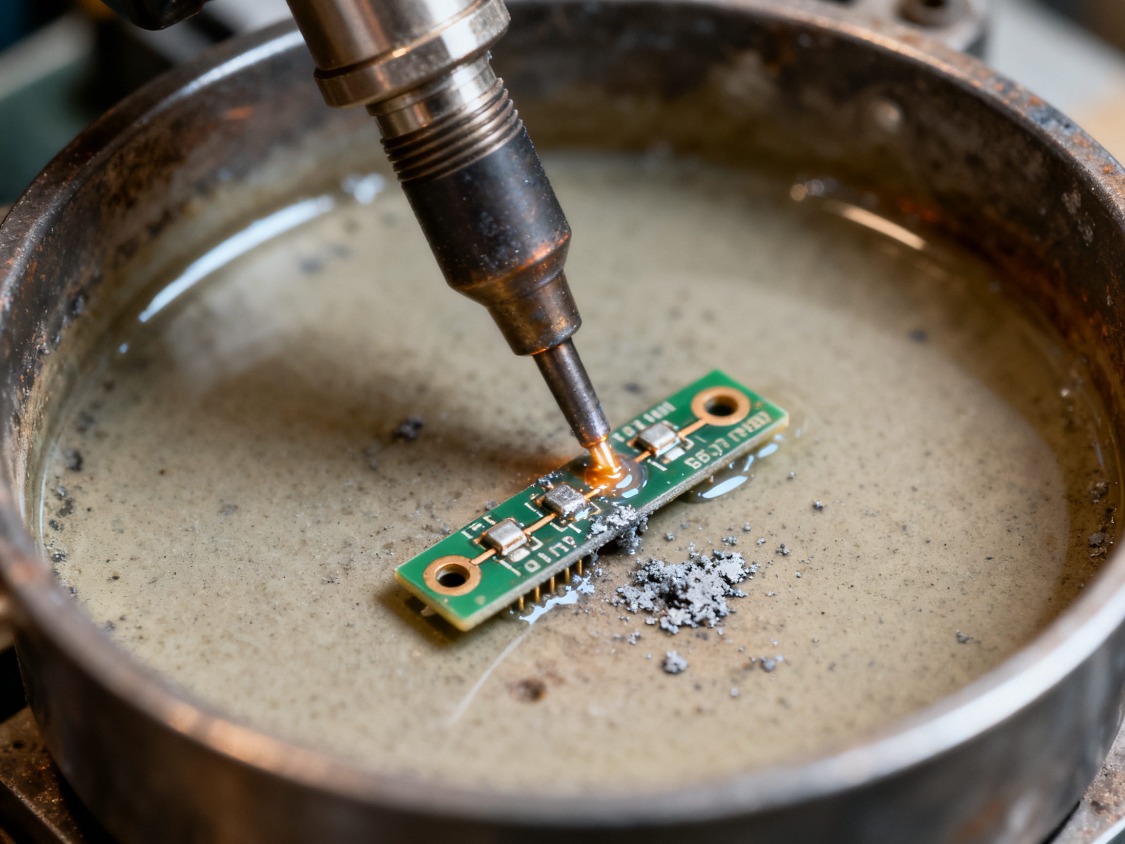
Case Study: Resolving Solder Bridging at Scale
A defense contractor was experiencing 3,200 ppm defect rates on their navigation system PCBs. Initial investigations blamed the solder alloy, then the flux, then the board design. After bringing in an outside consultant, the real problem surfaced: inconsistent nozzle heights across the solder pots. Some nozzles sat 0.5mm too high, creating turbulent solder flow that splashed between pads.
The fix took two hours. Calibrating nozzle heights and adding a daily verification step brought defect rates below 400 ppm within a month. No equipment replacement needed. Just attention to detail and consistent procedures.
That story shows why troubleshooting matters. Most problems have simple causes even when they look complicated at first glance.
Future Trends in Selective Soldering
The selective soldering process keeps evolving, and 2026 is bringing some significant changes. Here’s what’s shaping the future of this essential manufacturing technique.
AI and Smart Process Control
Artificial intelligence has started transforming how manufacturers optimize their selective wave soldering process. AI-powered inspection systems now catch defects that traditional AOI misses. Machine learning algorithms analyze thousands of solder joints per minute, identifying patterns that indicate problems before they become defects.
Some facilities in Asia have deployed AI systems that automatically adjust solder parameters in real time. When the algorithm detects a slight drift in joint quality, it tweaks the preheat temperature or solder volume without human intervention. This means fewer callbacks and less rework.
Lead-Free and Environmental Compliance
Environmental regulations keep pushing manufacturers toward lead-free processes. The EU’s RoHS directives and similar standards worldwide have accelerated this shift. Lead-free solder alloys require higher processing temperatures, which puts more stress on components.
Manufacturers are responding by investing in equipment that handles these higher temperatures reliably. Companies like Shenzhen Chuxin Electronic Equipment Co., Ltd. now offer systems specifically designed for lead-free production. Their lead-free reflow ovens and compatible selective soldering machines help facilities meet compliance while maintaining quality.
From Our Experience: Meeting environmental standards while keeping defect rates low requires equipment designed for lead-free processes from the ground up. The investment pays off in market access and reduced liability.
Industry 4.0 Integration
The connected factory is becoming reality in selective soldering. Modern machines now include IoT sensors that feed data to central dashboards. Managers track temperature profiles, solder usage, and throughput in real time from anywhere.
Predictive maintenance has become standard on newer equipment. Instead of waiting for a nozzle to fail or a solder pot to need cleaning, systems alert operators when wear patterns suggest an upcoming problem. This reduces unexpected downtime significantly.
Cloud-based analytics platforms aggregate data across multiple production lines. When one facility discovers a better parameter setting, that knowledge gets shared across the network instantly.
The future looks bright for selective soldering techniques. AI optimization, environmental compliance, and smart connectivity are making these systems more reliable and efficient than ever. Manufacturers who adopt these trends early will stay competitive in an increasingly demanding market.
Conclusion: Mastering Selective Soldering for Modern Manufacturing
Let’s bring everything together. Selective soldering has become essential for anyone working with modern electronics. The precision it offers simply cannot be matched by older methods like full wave soldering, especially when you are dealing with sensitive components and dense board designs.
The key practices we covered all connect to real results on the production floor. Proper preheating prevents thermal shock and keeps defect rates under 500 ppm. Flux management ensures clean joints that flow properly. Regular equipment maintenance catches problems before they become costly recalls. And smart nozzle selection makes the difference between a flawless joint and a bridge that fails in the field.
But knowing these practices is only half the battle. Applying them consistently matters more than any single technique. Even the best equipment fails when maintenance slips or parameters drift.
So what should you do next? Here is a quick checklist to guide your next steps.
Expert Checklist: Your Selective Soldering Action Plan
Review your preheat profiles for each board design
Audit your nozzle inventory and replace worn tips
Check flux application rates and adjust if needed
Schedule regular calibration for your solder pots
Consider AI-powered inspection if defect rates stay high
Evaluate lead-free compatible equipment for environmental compliance
If your current equipment struggles with lead-free processes or keeps generating high defect rates, it might be time to explore modern selective soldering systems designed for today’s manufacturing demands. Facilities upgrading in 2026 are seeing significant improvements in both quality and throughput.
The manufacturers who stay ahead are the ones who treat selective soldering as an ongoing optimization process, not a set-it-and-forget-it operation. Your next improvement might be closer than you think.