
Benefits of Remote Work
Remote work offers numerous advantages, including flexibility, reduced commute time, and improved work-life balance.
Flexibility
Employees can design their own schedules and create a workspace that suits their needs, leading to increased productivity.
Cost Savings
Working from home eliminates commuting costs and reduces expenses related to office attire and meals.
Improved Work-Life Balance
With the ability to better integrate personal and professional responsibilities, remote workers often report higher job satisfaction.## Understanding Selective Wave Soldering: Core Principles and Technology
Let’s be real. If you’ve ever watched a board full of heat-sensitive components roll through a wave soldering machine, you probably held your breath. One wrong move and those tiny SMD parts you’ve already mounted? Gone. Toast.
That’s exactly why selective wave soldering showed up on factory floors, and honestly, it changed everything for manufacturers dealing with mixed-technology boards.
What Is Selective Wave Soldering, Anyway?
Selective wave soldering is a precision process that puts molten solder exactly where you need it, and nowhere else. Instead of dunking an entire PCB through a solder wave, the machine targets specific through-hole joints while keeping all the surrounding components safely shielded from thermal stress.
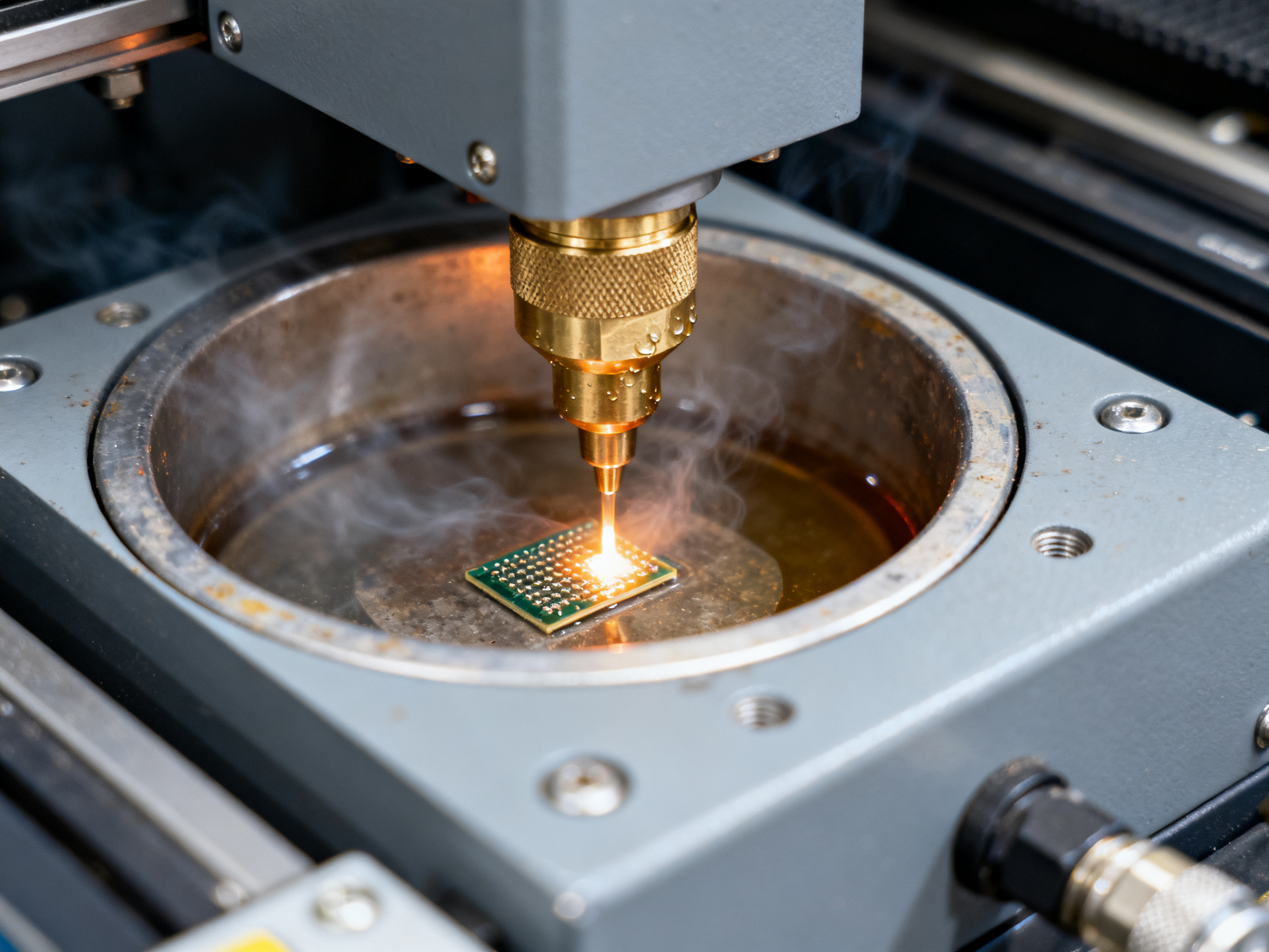
The technology works through programmable nozzles that position precisely over individual connection points. Flux gets applied only to the areas that need it, then a mini-wave or directed solder jet wets the joint while everything else stays cool and protected.
This matters because modern electronics assemblies are crowded places. You’ve got through-hole connectors sitting right next to fragile BGAs, QFNs, LEDs, and electrolytic capacitors. Standard wave soldering would expose all of them to the same heat bath. Selective soldering says “nope, we’re only touching what needs touching.”
The Real Advantages for Your Production Line
Manufacturers gravitate toward selective wave soldering for a few reasons that actually show up on the factory floor.
First, you skip the expensive masks and carriers that wave soldering needs to protect sensitive areas. Those custom fixtures take time to make and cost real money. With selective soldering, the machine handles the targeting digitally.
Second, it plays nice with boards that already have SMT parts attached via reflow. The through-hole connections get finished without reheating components that are already in place and happy.
Third, modern systems integrate with existing production protocols and can handle mixed component technologies in a single pass. So boards with connectors, switches, and heat-sensitive modules all get processed without multiple setups or manual touch-up.
The strongest practical users of this technology tend to be sectors building dense mixed-technology boards: telecom equipment, industrial control systems, automotive electronics, and data-center optical modules. If your board has both surface-mount and through-hole parts, selective soldering probably deserves a look.
How It Works: The Basic Setup
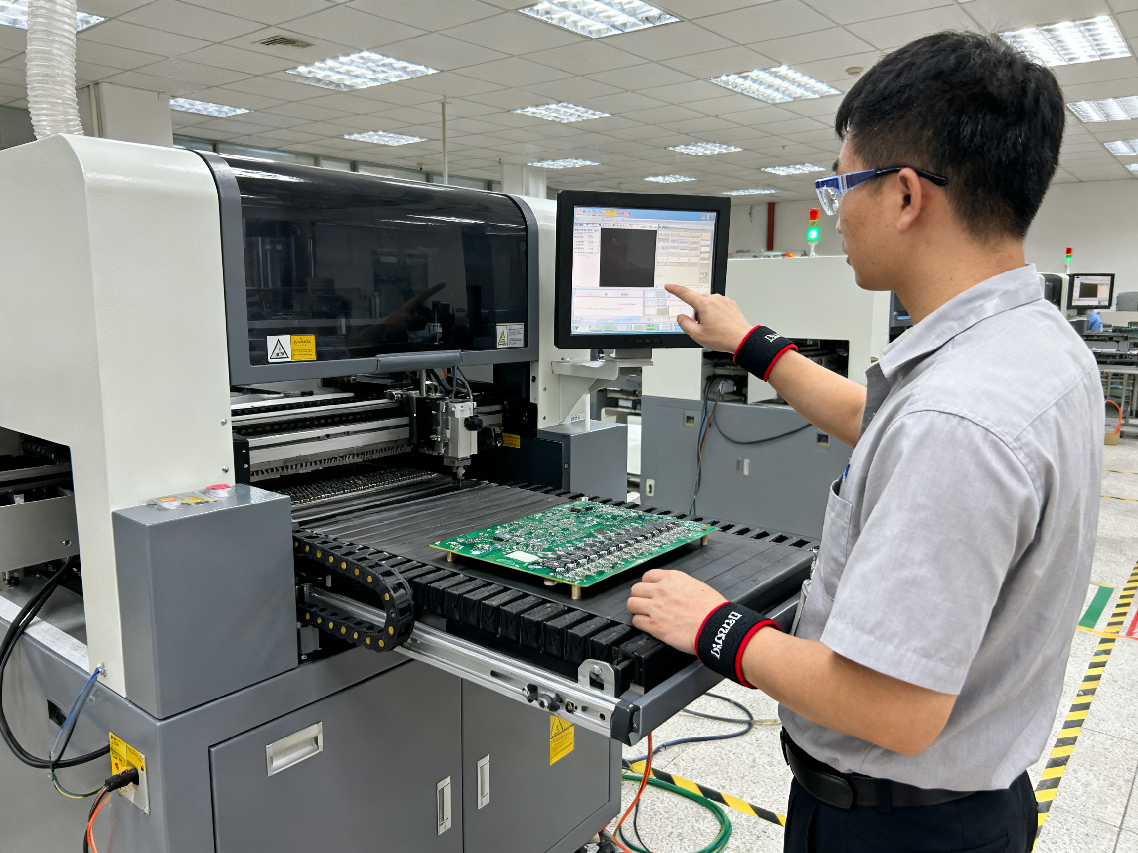
A selective soldering system has several parts working together. You’ve got the flux application system, the preheat zone, the solder pot with its pump and nozzle assembly, and the motion control that positions everything correctly.
The solder delivery itself usually happens one of two ways. Omnidirectional miniwave heads create a small, controlled wave that the board passes over at an angle. Directional nozzles confine the solder more tightly to the target lead or pad, which comes in handy when neighboring components are sitting close by.
Nozzle choice matters. Get it wrong and you either get incomplete joints or bridges on tight spacing. The good news is that newer systems have gotten smarter about this, and some manufacturers now offer maintenance-free nozzle designs that reduce the cleaning burden between shifts.
The Process Parameters That Actually Count
Here’s the thing: there’s no magic temperature setting that works for every board. The right preheat temperature, solder contact time, and wave height all depend on your specific board thermal mass, copper distribution, flux chemistry, and component heat tolerance.
That said, most lead-free selective soldering runs with pot temperatures somewhere between 280 and 320 degrees Celsius, with solder contact times around 3 to 4 seconds. Preheat typically targets board topside temperatures in the 100 to 130 degree range, but you’ll want to validate that against your actual flux and assembly.
The critical point from the technical literature is this: always validate settings on your actual PCB, measuring real topside component temperatures and joint results. Trust the flux supplier’s profile window, then prove it out with thermal profiling.
Where Selective Soldering Fits in Your Manufacturing Flow
The typical hybrid flow looks like this: reflow the SMT parts first, run selective soldering for through-hole areas second, then handle any manual touch-up or rework as a final step for exceptions the automation couldn’t reach.
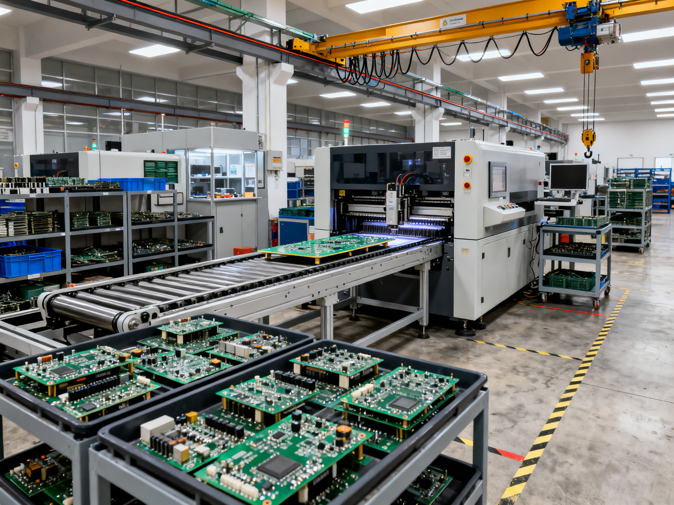
This approach keeps heat-sensitive components protected throughout while still achieving high throughput on the joints that need wave-quality filling. For mid-to-high volume production of complex boards, the efficiency gains add up quickly.
Companies using modern selective soldering systems report that the consistency and repeatability beat manual soldering by a wide margin. Once you’ve got the recipe dialed in for a board, it runs the same way board after board, shift after shift. That predictability alone makes a big difference for quality assurance and production planning.
Selective wave soldering has become a core part of mixed-technology assembly because it solves problems that neither standard wave nor hand soldering can touch. If you’re working with dense, complex boards and need reliable through-hole connections without risking your existing assembly, this technology deserves serious consideration.
Why Electronics Manufacturers Are Adopting Selective Wave Soldering
Here’s what keeps production managers up at night. You’ve got a board loaded with expensive BGAs, heat-sensitive LEDs, and a handful of through-hole connectors that still need soldering. Run it through standard wave and you risk cooking everything else. Hand solder it and you’re looking at inconsistency, fatigue, and costs that eat into your margins board after board.
This is exactly why selective wave soldering has gone from niche tool to production floor essential in 2026.
The numbers tell a pretty compelling story. One industry source reports that selective soldering can slash defects by 10-15% compared to traditional wave on mixed-technology boards, and by 20-30% compared to hand soldering. That’s not a marginal improvement. That’s the difference between hitting your quality targets and scrambling to explain yield losses to your customers.
And when you look at hand soldering specifically, the gap gets even wider. Manual soldering often runs defect rates around 1,000 to 5,000 DPMO (defects per million opportunities). Robotic selective systems? We’re talking 50 to 200 DPMO. That’s a 95-98% improvement in consistency.
The financial case adds up too. Manufacturers report conversion cost reductions of 51-78% per board assembly in some cases. Payback on equipment typically lands in the 9-18 month range for mid-volume operations. For a busy contract manufacturer running thousands of boards per week, those savings compound fast.
We ran the numbers on a typical mixed board scenario last quarter. Traditional wave with protective carriers and masks? Expensive upfront tooling, long setup times, and still some thermal risk. Hand soldering? Labor costs climbing every year, plus that quality rollercoaster. Selective wave let us process the same board without the fixturing expense and with automated repeatability. The recipe gets dialed in once and it runs exactly the same, shift after shift.
The sectors moving fastest to this technology make sense when you think about it. Industrial control equipment, telecom infrastructure for 5G, automotive electronics, and data-center optical modules all have one thing in common: dense mixed-technology boards with components you absolutely cannot reheat or expose to a full solder wave.
One case that caught my attention recently: Kamstrup reported 20% higher throughput after switching to a newer multi-nozzle selective system compared to their older 6-pot machine. They also reclaimed about 6 meters of factory floor space. Six meters might not sound like much until you start looking at real estate costs in manufacturing facilities.
The core appeal comes down to protecting what you’ve already built. Once your SMT components are reflowed and in place, selective soldering lets you finish the through-hole connections without touching anything else. No masks, no carriers, no crossed fingers hoping the adjacent parts survive the thermal ride.
Manufacturers are also discovering that the process works well with lead-free alloys, which have become the standard for most commercial electronics. The tighter thermal control and localized heating mean you can run those higher process temperatures without baking the whole board.
So what’s the honest bottom line? If you’re still doing significant hand soldering or wrestling with wave solder fixtures for complex boards, selective wave soldering deserves a serious look. The quality improvements alone usually justify the investment within a year, and the consistency gains make production planning so much easier.
The technology isn’t magic. You’ll still need good programming, proper preheat settings, and the right flux for your board. But for manufacturers working with mixed assemblies where thermal protection matters, this process has become basically non-negotiable.## How Selective Wave Soldering Works: The Technical Process
Alright, so you want to know what actually happens inside one of these machines. Fair warning: there’s a bit more going on than just “point and solder.” But once you see the pieces, the whole thing clicks together nicely.
The Flux Application Step
Everything starts with flux. And not just dumping it everywhere like some kind of solder tsunami. The system applies flux exactly where it’s needed, using either drop-jet dispensing or micro-spray systems that target individual through-hole locations.
The reason this matters so much is that flux does several jobs at once. It cleans oxides off the metal surfaces, promotes wetting so the solder actually sticks, and protects the joint from re-oxidation during the heating cycle. Put it in the wrong place and you’ll get bridging or poor fill. Put it in the right place and you’ve got a clean, reliable connection.
We’ve tested both jet and spray systems over the years, and honestly the choice comes down to your board density. For tight spacing with neighboring SMT parts, jet dispensing gives you tighter control. Spray works well when you’ve got more breathing room and want faster coverage.
The Preheat Zone: Getting Ready for Heat
Next up, the board rolls into the preheat zone. This isn’t optional or just a nice-to-have. Preheating serves two critical functions: it drives off volatile solvents in the flux so you don’t get spatter when the solder hits, and it brings the board up to temperature gradually so components don’t crack from thermal shock.
Most setups run topside board temperatures somewhere between 100 and 130 degrees Celsius for lead-free work. The exact number depends on your board thickness, copper weight, and flux chemistry. Heavier boards with more thermal mass need longer preheat times to reach uniform temperature throughout.
Here’s the mistake people make all the time: they set preheat by the heater temperature rather than measuring actual board temperature. Your thermocouple belongs on the board itself, not just pointing at the heating element. Trust me on this one.
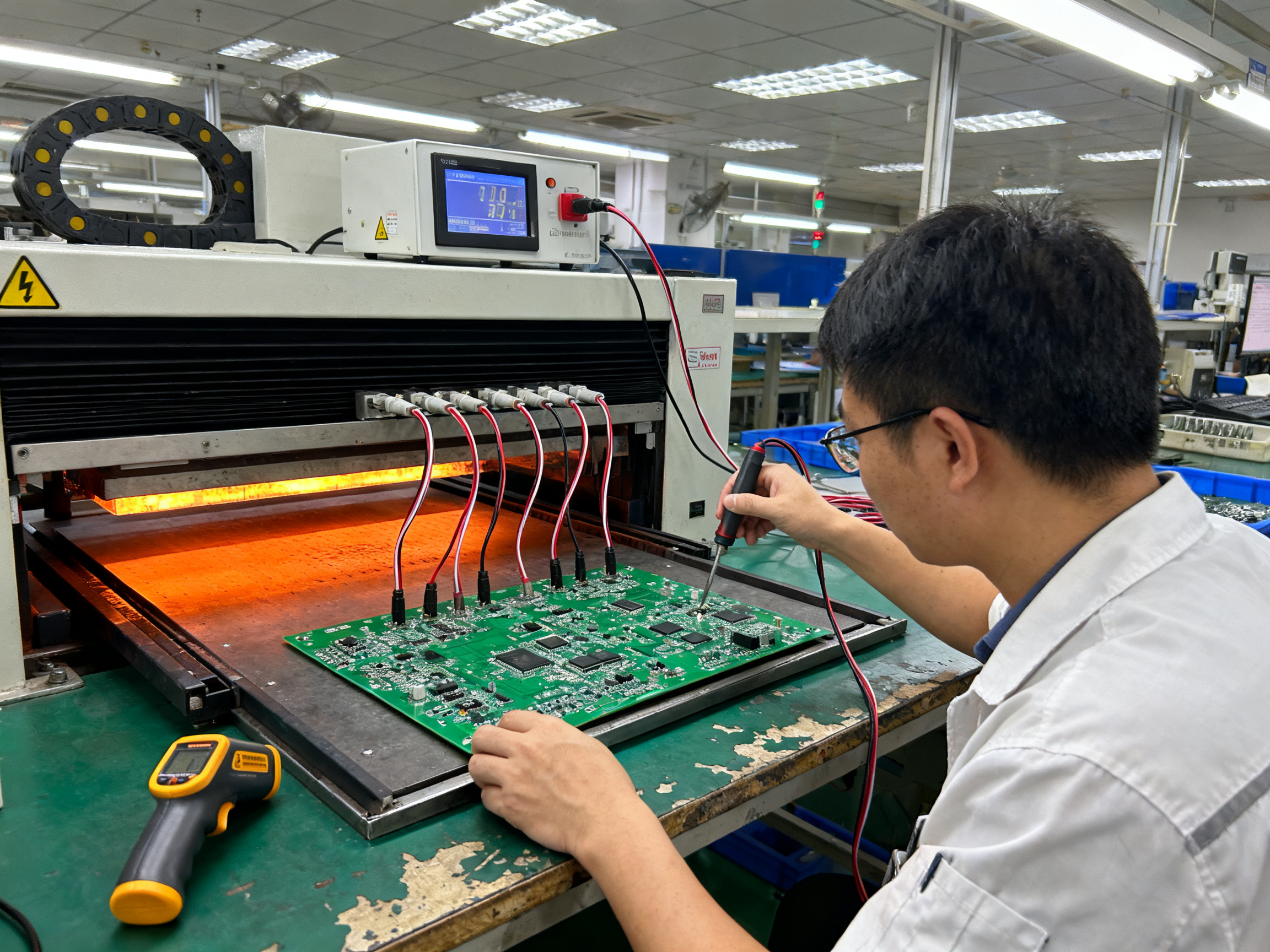
Pro Insight: The most common configuration mistakes we see in the field come down to three things. First, setting preheat by heater setpoint instead of measured board temperature. Second, ignoring flux-specific limits and assuming one profile works for every chemistry. Third, using excessive flux or placing it poorly when neighboring components are sitting close by. Get those three right and you’ll avoid most of the headaches we see from teams new to selective soldering.
The Solder Wave Delivery
Now for the main event. The solder wave itself gets delivered through one of two main nozzle designs: wettable omnidirectional miniwave heads or nonwettable directional nozzles.
Miniwave heads create a small, controlled wave that the board passes over, usually at a slight angle like 5 to 10 degrees. These work well when you need a broader contact area and the board geometry allows for it. Directional nozzles confine the solder much more tightly around the target lead or pad, which comes in handy when neighboring components are sitting just a few millimeters away.
The pot temperature for lead-free selective soldering typically runs between 280 and 320 degrees Celsius. That’s noticeably hotter than standard wave soldering because the localized process needs the thermal reserve to wet properly through the hole.
Solder contact time usually lands in the 3 to 4 second range, though it can vary based on your specific board design and copper distribution. Too short and you’ll get incomplete hole fill. Too long and you risk damaging nearby components or creating icicles.
Nozzle choice matters more than most people realize. Get it wrong and you either get insufficient joints or bridges on tight spacing. The good news is that newer systems have gotten smarter about this, and some manufacturers now offer maintenance-free nozzle designs that reduce the cleaning burden between shifts.
The Motion Control Piece
Everything gets positioned by precision motion control that moves the nozzle assembly to each target location. Modern systems use x/y positioning with accuracy around 0.15mm or better. The machine positions the flux head, then the solder nozzle, following a programmed recipe that tells it exactly where to go and how long to stay.
One thing worth mentioning: the program gets created offline using CAD data from your board design. You import the file, define your solder points, and the system generates the motion path. This means you’re not manually teaching each point on the physical board, which would be incredibly slow and introduce variability.
The whole process, from flux application through solder contact, happens in a controlled nitrogen atmosphere at most facilities. Keeping oxygen below 1000ppm reduces oxidation and helps the solder wet more consistently, especially at those higher lead-free temperatures.
When it all comes together properly, you get fill rates that meet IPC standards, minimal defects, and repeatability that hand soldering simply cannot match. Board after board, shift after shift, the same result.### Selective Soldering vs. Wave Soldering: Making the Right Choice
Here’s where things get practical. You’ve got a board in front of you and now you need to decide: wave or selective? Let’s break it down so you can make the call that makes sense for your situation.
The Core Difference
Traditional wave soldering does exactly what it sounds like. The entire bottom of your board passes through a wave of molten solder. Everything gets coated. This works great for simple boards with only through-hole parts. But throw some heat-sensitive surface-mount components into the mix? That’s where trouble starts.
Selective wave soldering works differently. It positions solder only where you need it, keeping everything else cool and protected. This approach handles those complex boards with mixed technologies without risking damage to sensitive parts.
What Drives the Decision
The choice between these two processes depends on four main factors:
- Board complexity and component mix
- Thermal sensitivity of mounted parts
- Production volume requirements
- Quality and consistency targets
Simple boards with only through-hole components and no thermal concerns? Wave soldering might be your answer. Dense mixed-technology boards with BGAs, LEDs, and connectors all sharing the same substrate? Selective soldering is usually the better fit.
The reality is that most modern assemblies fall into that second category. Telecom equipment, industrial controls, automotive electronics, and data-center modules all have one thing in common. They pack a lot of different component types into tight spaces, and they need every joint reliable.
| Factor | Wave Soldering | Selective Wave Soldering |
|——–|—————-|————————-|
| Best for | Simple through-hole boards, high volume | Mixed-technology boards, complex assemblies |
| Thermal exposure | Full board immersion | Localized to target areas only |
| Fixturing needs | Carriers and masks often required | Minimal or no fixturing |
| Setup time | Can be lengthy for complex protection needs | Program once, run repeatedly |
| Quality on mixed boards | Risk of component damage without protection | Protected processing, higher first-pass yield |
| Throughput | High for compatible boards | Lower per board, but fewer quality issues |
Expert Tip: Industry guidance suggests that when production involves boards with mixed SMT and through-hole components, selective soldering typically delivers better total cost of ownership when you factor in fixturing, rework, and quality control. For straightforward through-hole boards running at high volume, wave soldering’s simplicity becomes an advantage.
When Each Process Wins
Wave soldering still makes sense for high-volume production of boards that are fully compatible with full-wave immersion. If your board has no underside components, no heat-sensitive parts, and you’re running thousands of identical units, wave soldering can be the more economical path.
Selective soldering wins when your board design demands it. When you’ve got expensive components already mounted via reflow, when neighboring parts can’t survive thermal exposure, when spacing is tight enough that solder spread would cause bridging. The cost premium gets justified by what you avoid: damaged components, rework, scrapped boards.
And here’s the thing that often gets overlooked in the cost calculation. When selective soldering reduces your defect rate from typical hand-soldering levels down to automated process levels, the savings on rework labor and scrap add up fast. Those numbers usually show up in the payback calculation that makes selective equipment pay for itself within a year or two for mid-volume operations.
Both processes have their place on the modern production floor. The key is matching the process to the board, not forcing everything through one method because that’s what you’ve always done.
Selective Soldering vs. Hand Soldering: Automation vs. Manual Processes
Now here’s where things get really interesting. We’ve talked about how selective soldering compares to wave soldering, but what about good old-fashioned hand soldering? You know, the method where a skilled operator holds a iron and touches each joint one by one?
Look, hand soldering has been around forever and there’s a time and place for it. But when you’re running production, the cracks start showing fast.
The Human Variability Problem
Here’s the thing about hand soldering: every joint reflects the skill, mood, and fatigue level of whoever’s holding the iron. An operator who’s been soldering for eight hours will produce different results than one who started an hour ago. Temperature variations in the iron tip, slight angle differences, inconsistent contact time, solder quantity applied by hand. All of it adds up.
We’ve seen defect rates from manual soldering run anywhere from 1,000 to 5,000 DPMO. That’s defects per million opportunities, by the way. Some of that comes from bridges, some from cold joints, some from pads lifted right off the board. And when you’re building thousands of units per week? Those percentages bite into your margins hard.
One manufacturer I spoke with last year described their hand-soldering operation as a “quality rollercoaster.” Some shifts hit good numbers. Others? Complete chaos. They never knew which they’d get until the AOI results came back.
What Automation Brings to the Table
Switch to robotic selective soldering and those numbers drop dramatically. We’re talking 50 to 200 DPMO in well-tuned systems. That’s a 95-98% improvement in consistency, and the difference mostly comes down to eliminating the human variable from the equation.
Once you’ve got your recipe programmed, the machine does the same thing, the same way, every single time. Same solder temperature. Same contact time. Same flux amount. Same nozzle positioning. Board 1,000 looks exactly like board 1.
Plus, automated systems log everything. You’ve got documented process parameters that make quality assurance and regulatory compliance so much easier. Try getting that kind of traceability from a guy with a soldering iron.
The Real Cost Comparison
Here’s where people get surprised. Hand soldering looks cheaper on paper because there’s no big equipment purchase, right? But when you add up labor costs, rework expenses, scrap rates, and the ever-present risk of quality escapes reaching your customers, the math changes fast.
Manufacturers report conversion cost reductions of 51-78% per board assembly when switching from hand soldering to selective automation. Payback on equipment typically lands in the 9-18 month range for mid-volume operations. For a busy contract manufacturer running thousands of boards weekly, those savings compound quickly.
Expert Tip: Industry guidance suggests that when production involves boards with mixed SMT and through-hole components, selective soldering typically delivers better total cost of ownership when you factor in fixturing, rework, and quality control. For straightforward low-volume runs or one-off repairs, hand soldering still has its place.
The honest answer is that both methods have their role. Hand soldering works for rework, prototypes, and situations where you’ve got maybe 10 boards total. But once you’re scaling up, the consistency gains from automation usually justify the investment within a year or two.
So if you’re still doing significant hand soldering for production work, it might be time to run the numbers on what that variability is actually costing you.## Lead-Free Selective Soldering: Challenges and Solutions
Here’s something nobody talks about enough in this industry. Lead-free soldering sounds great on paper. Better for the environment, better for regulations, better for export markets. But try running your first lead-free profile on a selective soldering system and you quickly discover why the transition took years to shake out properly.
The core issue comes down to temperature. Lead-free alloys need it hotter, much hotter, to wet and flow the way you need them to.
Why Lead-Free Demands More Heat
Traditional tin-lead solder melts around 183 degrees Celsius and works happily at pot temperatures around 250 degrees. Lead-free SAC305 and SAC387? They liquidus around 217-220 degrees, but for selective soldering you typically run pot temperatures between 280 and 320 degrees. That’s a 30 to 70 degree jump over standard wave parameters.
That extra heat has consequences. You’re pushing more thermal energy into the board every time the solder makes contact. Components that were fine under leaded processing suddenly find themselves at the edge of their ratings. LEDs, plastic connectors, and electrolytic capacitors tend to be the first to complain.
We’ve seen it happen. A board that ran clean for years under leaded processing starts showing intermittent failures or cosmetic damage once the lead-free conversion happens without proper profile adjustment. The solder joints look fine. The components underneath have had enough.
From Our Experience: Managing lead-free process temperatures in selective soldering comes down to three things we learned the hard way. First, always validate your preheat by measuring actual board temperature, not heater setpoints. Second, start conservative on solder contact time and add increments only as needed for hole fill. Third, flux selection matters more with lead-free because the activators have to work harder at those higher temperatures. Get those three right and most of the thermal stress issues fade away.
How Modern Systems Handle the Thermal Challenge
Here’s the good news. Equipment makers have gotten much smarter about this. Modern selective soldering systems include features specifically designed to manage lead-free thermal demands without cooking your board.
Advanced preheat configurations now offer multi-zone heating with better control over ramp rates. Instead of dumping heat onto the whole board at once, you bring it up gradually to target temperature. Most guidance suggests topside board temperatures between 100 and 130 degrees Celsius for lead-free work, with the exact number depending on your flux chemistry and board thermal mass.
Solder wave dynamics have improved too. Nozzle designs confine the thermal exposure more tightly, and some systems offer oscillating or pulsed wave patterns that deliver heat in controlled bursts rather than continuous contact. This matters because the difference between a 3-second contact and a 5-second contact at 300 degrees can be the difference between a good joint and a damaged component sitting 2 millimeters away.
Nitrogen inerting has become almost standard for lead-free selective soldering. Keeping oxygen below 1000ppm reduces oxidation at the solder surface and helps the molten alloy wet more consistently. Cleaner wetting means you can sometimes run slightly cooler or shorter contact times, which takes pressure off temperature-sensitive neighbors. Some facilities push further, targeting oxygen levels below 50ppm for particularly sensitive assemblies.
Compatibility Considerations for Mixed Assemblies
This is where things get complicated for manufacturers still running some leaded assemblies alongside their lead-free products. The two processes want different parameters, and switching between them takes time.
If you’re processing both types on the same equipment, you’ll need separate recipes with distinct preheat profiles, pot temperatures, and contact times. Some facilities solve this by maintaining dedicated solder pots for each alloy family. Others run lead-free only and accept the longer changeover when leaded work comes through.
Board design also plays a role. Lead-free compatible assemblies typically need more thermal margin built in, which sometimes means thicker copper, larger pads for heat spreading, or strategic component placement to keep sensitive parts away from solder contact zones. Retrofitting existing designs for lead-free compatibility often requires layout revisions and re-validation.
The process validation step becomes non-negotiable when you’re making the switch. Run thermal profiling on actual boards, measure component body temperatures during processing, and check joint quality against IPC standards. Don’t assume that lead-free parameters from a datasheet will work for your specific assembly. They rarely do without some adjustment.
Making Lead-Free Work in Practice
The challenges are real, but so are the solutions. Lead-free selective soldering has become standard practice across the industry, and the techniques for managing it are well-established at this point.
Start with quality flux rated for lead-free applications. Your flux needs to survive those higher temperatures without breaking down prematurely and still clean the joint effectively. Then dial in your preheat to bring the board to temperature uniformly, not just at the surface.
From there, validate your contact parameters with your actual board, your actual components, and your actual acceptance criteria. Make small adjustments, check results, and iterate until you’ve got a recipe that produces reliable joints without stressing nearby parts.
Once you’ve got it locked in, lead-free selective soldering runs just as consistently as its leaded predecessor. The setup takes more care upfront, but the day-to-day operation feels the same.
Selective Soldering Advantages and Disadvantages: A Balanced Assessment
Let’s be straight with you. Every manufacturing technology has trade-offs, and selective wave soldering is no different. Before you commit to anything, here’s what you actually gain and what might give you pause.
The Upsides Worth Knowing About
Here’s what makes selective soldering worth a serious look. First, you get exceptional precision on complex assemblies. The machine targets exactly where solder goes and nowhere else, which matters when you’re working with dense mixed-technology boards.
Thermal exposure stays localized. Your already-mounted SMT parts stay protected while through-hole joints get finished properly. That alone removes a lot of risk from the process.
Defect rates drop significantly. We’re talking 50 to 200 DPMO for robotic selective systems versus 1,000 to 5,000 DPMO for hand soldering in most operations. Some manufacturers report 10 to 15 percent fewer defects compared to wave soldering on mixed boards, and 20 to 30 percent fewer compared to hand soldering on the same assemblies.
Consistency becomes automatic. Once your recipe is dialed in, it runs the same way board after board, shift after shift. That predictability makes quality assurance so much simpler because you’ve got documented process parameters for every batch.
For S&M Co. Ltd. customers in consumer electronics, semiconductors, and military electronics, these advantages address real pain points. The precision matters for high-density assemblies. The reduced thermal exposure protects expensive components. The documented consistency supports compliance requirements that aerospace and military customers increasingly demand.
The Challenges You Should Factor In
Now for the honest part. Equipment costs more upfront compared to standard wave solder systems. That’s a real number to swallow, especially for smaller operations.
Throughput on simple, full-board soldering tends to be slower than traditional wave. If you’re running high volumes of straightforward through-hole boards without complex thermal requirements, this gap matters.
Setup takes more expertise. Your team needs training on programming, parameter optimization, and maintenance. That’s time and money before you see returns.
Payback typically lands in the 9 to 18 month range for mid-volume operations. That math works well when defect and rework costs are high. It stretches longer when your current process is already stable.
| Factor | Selective Soldering | Wave Soldering | Hand Soldering |
|——–|——————-|—————-|—————-|
| Defect Rate (DPMO) | 50-200 | 500-1000 | 1000-5000 |
| Equipment Investment | Higher | Lower | Minimal |
| Per-Board Throughput | Moderate | High | Low |
| Consistency | Excellent | Good | Variable |
| Setup Complexity | Moderate | Low | N/A |
| Process Documentation | Full | Partial | Limited |
The Real Answer Depends on Your Situation
Here’s what actually matters when you’re deciding. Think about your board profile first. Dense mixed-technology assemblies with heat-sensitive parts? Selective soldering usually wins the economics over time. Simple through-hole boards running at high volume without thermal concerns? Wave soldering might still be your better path.
Then look at your quality requirements. Are defect rates and consistency driving customer complaints or compliance needs? That shifts the math significantly.
The key is matching the process to the actual problem you’re solving, not picking one because it’s newer or everyone seems to be talking about it.
Choosing the Right Selective Soldering System for Your Operations
Here’s where things get real. You’ve done your research, read the specs, and now you need to actually pick a system that fits your factory floor. This is where a lot of buyers get stuck, so let me walk you through what actually matters when you’re evaluating equipment.
What Your Board Demands First
Start with your actual product, not the marketing brochure. What’s the biggest board you’ll run through the machine? What’s the thermal mass like? How many solder points are we talking about per board, and how are they distributed?
Board size capabilities vary significantly across manufacturers. Some systems handle boards up to 508mm class dimensions, while others go up to 1,200 by 610mm. If you’re building telecom infrastructure boards or large industrial controls, that working envelope matters a lot. Get a system too small and you’re manually handling boards that should flow through automation.
Nozzle Considerations That Actually Impact Your Day
Nozzle interchangeability is one of those features that doesn’t look important until you’re running production. Different board designs need different nozzle geometries. Tight spacing between through-hole points? You want directional nozzles that confine solder tightly. Larger pads with more breathing room? Omnidirectional miniwave heads give you flexibility.
Some newer systems offer maintenance-free nozzle designs, which reduces the cleaning burden between shifts. That sounds minor until you’re paying an operator to scrub nozzles every few hours.
Programming Flexibility Matters More Than It Seems
Your programming approach affects every board that comes through. Look for systems that offer offline programming from CAD data. You import your board file, define solder points, and the machine generates the motion path without needing a physical board present. This means your machine isn’t sitting idle while you teach it points on the production floor.
SEHO highlights 100% offline programming on some systems, which is worth considering if your changeover frequency is high.
Integration With Your Existing Line
Does the system work with your current protocols? For inline setups, check whether the equipment supports standards like IPC-HERMES-9852 or IPC-CFX for data exchange. ERSA’s VERSAFLOW 4 XL is explicitly described as IPC CFX-certified, which matters if you’re building a connected smart factory.
For offline or batch processing, integration might matter less, but think about your roadmap. Are you planning to move toward more automated flows in the next few years?
Thermal Management and Flux Systems
For lead-free work, your thermal management setup becomes critical. Look at preheat configurations, how well the system controls ramp rates, and whether nitrogen inerting is available. Nitrogen systems that keep oxygen below 1,000ppm help with process stability at those higher lead-free temperatures.
Flux application precision matters too. Drop-jet dispensing gives you tighter control on dense assemblies where neighboring components sit close by. Spray systems work fine when you’ve got more clearance to work with.
The Step Nobody Should Skip: Production Trials
Here’s my biggest piece of advice. Before you sign any purchase order, run your actual boards through the machine. Validate that it produces acceptable hole fill, check for bridging or icicles, confirm that nearby components aren’t seeing thermal stress, and verify repeatability across multiple boards.
No spec sheet tells you whether the system works for your specific board, your specific flux, and your specific quality standards. The validation step protects you from expensive surprises after installation.
From Our Experience: Managing lead-free process temperatures in selective soldering comes down to three things we learned the hard way. First, always validate your preheat by measuring actual board temperature, not heater setpoints. Second, start conservative on solder contact time and add increments only as needed for hole fill. Third, flux selection matters more with lead-free because the activators have to work harder at those higher temperatures. Get those three right and most of the thermal stress issues fade away.
Making the Final Call
When you’re comparing vendors, build a simple scoring matrix for your priorities. Weight board size capability, programming flexibility, changeover speed, service access, and total cost of ownership. Don’t just look at the sticker price. Factor in maintenance costs, consumables, nitrogen usage, and what your team needs for training.
For S&M Co. Ltd. customers building dense mixed-technology boards in consumer electronics, semiconductors, and military applications, the right selective soldering system should handle your thermal constraints, integrate with your existing quality protocols, and deliver consistent results board after board.
The goal isn’t the fanciest machine on paper. It’s the system that reliably solves your specific manufacturing challenges.### Getting Your Parameters Dialed In
Here’s what nobody tells you when you first get a selective soldering system: the manual settings are just a starting point. Your actual process needs to match your specific board, your flux, and your components.
The first thing to nail down is preheat. Don’t just set it to some number you found online and call it good. Get your thermocouple on the actual board topside and measure what temperature you’re really reaching. Most lead-free work lands somewhere between 100 and 130 degrees Celsius at the board surface, but heavy boards with lots of copper need more time to come up to temperature uniformly.
We learned this the hard way a few years back. We were running a profile that looked fine on paper, but turns out the board center was lagging behind the edges by about 15 degrees. Once we added more preheat zones and validated with actual board measurements, our hole fill problems basically disappeared.
Solder pot temperature for lead-free typically sits between 280 and 320 degrees Celsius. Contact time around 3 to 4 seconds works for most boards, though some designs need a bit more or less. The key is to start conservative and adjust upward only as needed for complete hole fill.
Pro Tip: When you’re validating your profile, check your flux supplier’s data sheet first. Different flux chemistries have different temperature limits, and what works for one might cause problems with another. Your flux is doing heavy lifting in that process, so treat it like a partner, not an afterthought.
The Maintenance Piece Nobody Wants to Talk About
Here’s a truth that gets glossed over in equipment brochures: maintenance keeps showing up on the schedule. Every single day, actually.
At minimum, you’re removing surface dross from the solder bath, checking solder level and topping off as needed, verifying your nitrogen flow is keeping oxygen below 1000ppm, and giving nozzles a quick once-over for damage or buildup. These tasks take maybe 10 minutes if you’re consistent about them.
Skip them and you’ll start seeing the consequences. Dross buildup changes how heat transfers to the board. Low solder level means inconsistent wave height. Dirty nozzles cause bridging or poor fill. It all compounds fast.
Weekly maintenance gets deeper. Thorough bath de-drossing, nozzle cleaning and inspection, flux head service. Monthly or quarterly, depending on your volume, you’re looking at alloy analysis to check copper contamination levels, pump inspection, and calibration verification on your temperature and oxygen sensors.
The good news is that newer systems have started to reduce some of this burden. Maintenance-free nozzle technologies have come a long way, which means less manual cleaning between shifts. But the fundamentals still apply. A clean system produces consistent results.
Building a Monitoring Routine That Actually Works
Statistical process control sounds fancy, but it doesn’t have to be complicated. At its core, you’re just tracking whether your process is behaving the way it should.
Pick a few key measurements that actually tell you something. Solder temperature deviation over time. Oxygen level trends. Wave height consistency. Hole fill rates from your quality checks. Defect patterns by shift or by board revision.
Graph these. Look for drift. If your solder temperature has been creeping up by 2 degrees over the last month, that’s worth investigating before it becomes a problem.
Run periodic capability studies on your critical joints. Measure actual barrel fill on sample boards. Check for bridging or icicles. Verify that nearby components aren’t seeing thermal stress. When you spot trends, act on them before they show up as quality escapes.
The goal isn’t perfect process control. It’s knowing when something is drifting so you can correct before you make bad boards. That’s really what optimization is: small adjustments over time, guided by real data from your actual production.
Your selective soldering system will reward the attention you give it. Treat the process like the precision tool it is, and it’ll keep producing reliable joints shift after shift, year after year.## Conclusion: Strategic Recommendations for Adopting Selective Wave Soldering
So where does that leave you? If you’ve been reading through this guide, you’re probably thinking about whether selective wave soldering makes sense for your operation. Let me give you the straight talk on how to think through that decision.
The Bottom Line on Selective Soldering
Selective wave soldering has earned its place as a critical technology for manufacturers producing complex electronics where quality, precision, and defect reduction matter. That’s not marketing speak. That’s what the numbers show: defect rates dropping from 1,000 to 5,000 DPMO with hand soldering down to 50 to 200 DPMO with robotic selective systems, and payback periods landing in the 9 to 18 month range for mid-volume operations.
The technology protects what you’ve already built. Once your SMT components are reflowed and in place, selective soldering finishes the through-hole connections without baking everything else in the process. That alone eliminates a whole category of production headaches.
Making the Investment Decision
Here’s how to approach it. Don’t buy equipment because everyone else seems to be talking about it. Buy it because you’ve done the analysis and the numbers make sense for your specific situation.
Start by honestly assessing your current defect costs, rework rates, and the price you’re paying in scrapped boards and customer complaints. Then look at your production requirements: Are you running dense mixed-technology assemblies? Do you have heat-sensitive components next to through-hole joints? Is hand soldering eating up your labor budget and producing inconsistent results?
If those questions keep pointing toward the same problems, selective soldering probably deserves serious consideration.
Final Recommendations Table
| Production Scenario | Recommended Approach | Key Consideration |
|———————|———————|——————-|
| Dense mixed boards with heat-sensitive parts | Selective wave soldering | Protects existing assembly investment |
| High-volume simple through-hole boards | Standard wave soldering | Maximum throughput, lower per-board cost |
| Low-volume or prototype work | Hand soldering with quality operator | Flexibility for exceptions and changes |
| Mixed production with some lead-free requirements | Selective with separate lead-free recipe | Validate both profiles thoroughly |
| Quality-critical aerospace or military | Selective with full documentation | Traceability supports compliance needs |
Looking Ahead
Here’s what I’m seeing in 2026. Electronics keep getting denser. Component packages keep getting smaller. Thermal sensitivity keeps increasing. That trend line doesn’t reverse. Manufacturers who have selective soldering capabilities are better positioned to handle the next generation of board designs without scrambling to retool or accept higher defect rates.
The technology isn’t standing still either. Multi-nozzle systems are pushing throughput higher, nitrogen control is getting more precise, and programming workflows are getting friendlier for operators who aren’t automation specialists.
If you’re working with complex assemblies and haven’t seriously evaluated selective wave soldering, now’s the time. Your competitors probably already have.