
Published: 12 October 2026
Last updated: 12 October 2026
Reading Time: 20 minutes
Written by: [Author Name]
Reviewed by: [Reviewer Name, Credentials]
—> Published: 12 October 2026
Last updated: 12 October 2026
Reading Time: 20 minutes
Written by: [Author Name]
Reviewed by: [Reviewer Name, Credentials]
Introduction: Planning an SMT Line for 2026 Production Requirements
If you’re overseeing electronics manufacturing in 2026, you already know the pressure is on from every direction. Customers want faster delivery. Quality inspectors demand tighter tolerances. Your procurement team keeps pushing for lower costs. And somewhere in the background, lead-free compliance requirements are quietly reshaping everything you thought you knew about soldering.
Here’s what production leaders are actually dealing with right now. Throughput targets keep climbing while changeover frequency increases because product life cycles have shortened dramatically. First-pass yield isn’t just a quality metric anymore; it directly impacts your cost per board and whether you hit quarterly targets. Traceability requirements, especially in automotive and aerospace, mean you need to know exactly which machine placed which component on which board at what time. And labor efficiency has become critical as skilled operators become harder to find and keep.
This guide walks you through the complete process of planning, selecting, and commissioning an SMT production line. We’ll cover everything from defining your actual capacity requirements to choosing the right equipment mix, designing a layout that works for your floor, and setting up the inspection and control systems that keep defects from reaching customers.
But here’s the thing. There is no single configuration that works for everyone. A high-volume consumer electronics line looks completely different from a flexible military manufacturing setup. Your board complexity, component package mix, production volume, changeover frequency, and applicable industry standards all shape what a “complete” SMT line actually means for your operation.
The sections that follow give you the framework to make those decisions with confidence.
About the Author
[Author Name] is [verified role/credential] with [verified experience] in SMT production-line planning, equipment integration, or electronics manufacturing. [Add one relevant, verifiable achievement or area of hands-on expertise; do not publish until completed.]
[Author Name] has spent [X] years working alongside production teams to design, commission, and optimize SMT lines for real factory conditions. From selecting the right placement machines to fine-tuning reflow profiles and tracking down defect root causes, [he/she/they] has seen what works and what wastes money.
This background shows up in every section of this guide. [Author Name] focuses on the decisions that actually matter when you are running a line, not just the specs on a sales sheet. For a complete profile and any relevant disclosures, including any relationship with equipment suppliers like S&M Co. Ltd., please visit [full author profile link].
1. What Is an SMT Production Line, and How Does It Work?
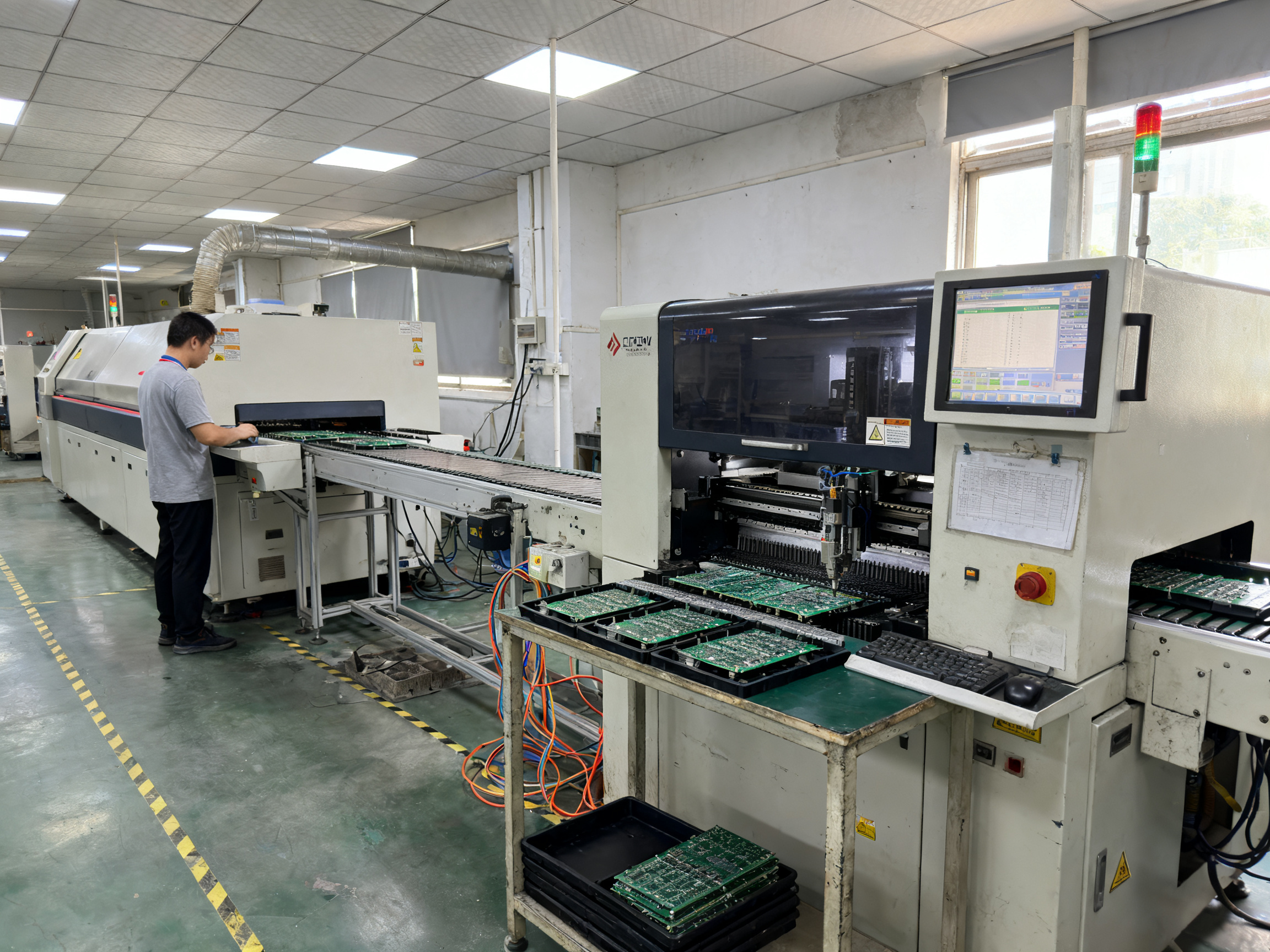
If you have been around electronics manufacturing, you have probably heard the term SMT machine thrown around. But here is the thing. An SMT machine is just one piece of the puzzle. A complete SMT production line is a whole system of machines working together to build circuit boards.
SMT stands for surface-mount technology. It is the way we attach tiny components directly onto the surface of a printed circuit board using solder paste and heat. Think of it like decorating a cake, except the decorations are resistors, capacitors, and microchips, and the frosting is solder that melts and holds everything in place.
The Basic Flow
A standard SMT line follows a sequence that has stayed pretty consistent over the years. It starts when bare circuit boards get loaded onto the line. From there, the boards move through several stations in order.
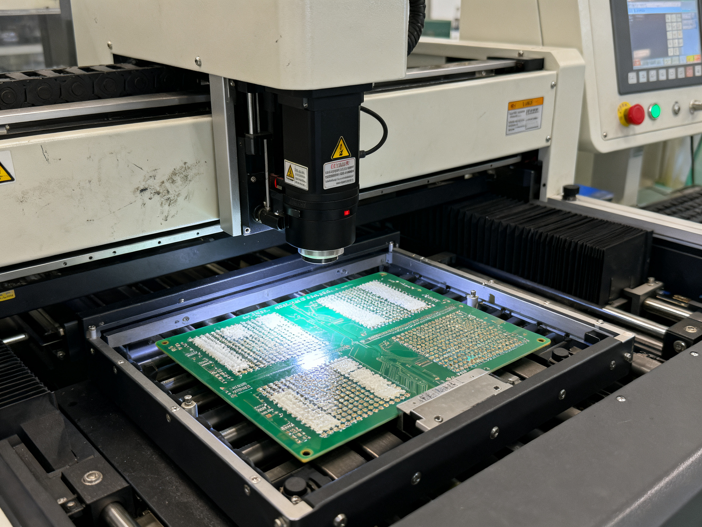
First, solder paste gets applied through a stencil. This is like screen-printing, but for electronics. Then a Solder Paste Inspection (SPI) system checks that the paste went down correctly before anything else happens.
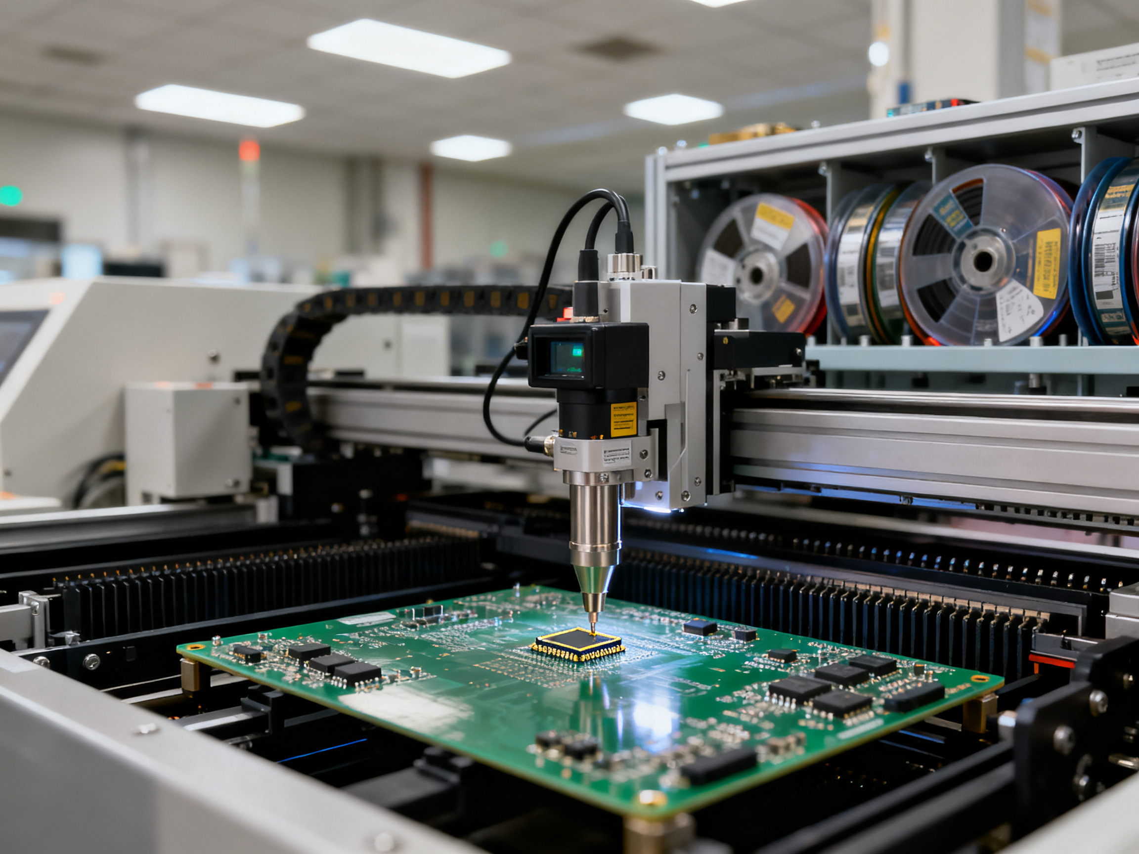
After that, components get placed onto the boards by automated pick-and-place machines. These machines are incredibly precise. They can place dozens of components per second. Once everything is positioned, the boards go through a reflow oven where controlled heat melts the solder and creates permanent connections.
Post-reflow inspection uses Automated Optical Inspection (AOI) and sometimes X-ray to catch defects that you cannot see with the naked eye, especially under chips with hidden connections. The boards then go through electrical testing and finally get unloaded.
SMT vs. Other Approaches
SMT is not the only way to build electronics. The older method is called through-hole, where components have leads that poke through holes in the board and get soldered on the other side. Through-hole is more durable for some applications, but it takes up more space and costs more to manufacture.
Many products today use mixed technology. That means SMT components on the surface plus some through-hole parts that need wave soldering or selective soldering to complete the assembly. If a board has connectors, heavy components, or parts that cannot survive reflow, those typically get added after the SMT process using wave or selective soldering methods.
The right approach depends entirely on your product. Consumer gadgets usually lean heavily on SMT for speed and cost. Automotive and aerospace boards often mix both technologies to balance reliability with manufacturing efficiency.
| Assembly Type | Best For | Key Characteristic |
|————–|———-|———————|
| SMT Only | High-volume, compact designs | Fast, cost-effective, miniaturization |
| Through-Hole Only | High-stress, rugged applications | Durable, repairable, but larger |
| Mixed Technology | Complex assemblies | Flexibility, combines strengths of both |
Why the Line Matters More Than Any Single Machine
Here’s something we see often. Teams get focused on the placement machine speed or the reflow oven temperature zones. Those things matter, sure. But the real magic happens when all the stations work together seamlessly.
A board that prints perfectly but places poorly will still fail. An excellent placement followed by a bad reflow profile creates opens, voids, or tombstoning. The line is only as strong as its weakest link.
That is why planning an SMT production line means thinking about the whole flow, not just individual equipment specs. Every station affects the next.
For a complete walkthrough of the process steps and a downloadable checklist, see our SMT manufacturing process PDF guide which covers each stage in detail.
Looking for a complete SMT production line? Shenzhen Chuxin Electronic Equipment Co., Ltd. specializes in lead-free reflow ovens, wave soldering systems, and turnkey SMT lines designed for high-density assemblies in consumer electronics, semiconductor, and military applications.
2. Define Product, Capacity, Quality, and Compliance Requirements
Before you start comparing placement machines or reflow ovens, you need to answer a basic question. What are you actually building, and how much of it do you need to produce? Sounds simple, right? But this step trips up more teams than you would expect.
Turn Your Product Data Into Equipment Specifications
Grab your board drawings and bill of materials. Now extract the numbers that will drive every equipment decision.
Board dimensions tell you the conveyor width and transport system you need. Panelization (how many boards are arrayed together) affects handling, stencil design, and inspection coverage. Component range, meaning the smallest passive size down to the largest BGA or QFN, determines placement-head requirements and feeder capacity.
Side count matters because double-sided assembly means double the process steps. Thermal mass is often overlooked but it directly impacts your reflow profile and oven zone configuration. A thick copper board with heavy ground planes behaves completely differently from a thin FR4 smartphone board.
Here is a quick checklist for translating product data into specs:
- Board dimensions and thickness
- Panel size and boards per panel
- Component package range (smallest to largest)
- BGA, QFN, and fine-pitch density
- Single-sided or double-sided assembly
- Copper weight and thermal mass
- Solder alloy and paste type requirements
Calculate Real Capacity, Not Just Machine Ratings
This is where many SMT planning efforts go wrong. Teams look at a placement machine rated at 50,000 components per hour and assume that is what they will get. But that number comes from a standardized test under ideal conditions.
IPC-9850 provides a useful benchmark for comparing placement equipment, but it does not predict your actual production rate. Your board mix, component distribution, feeder arrangement, changeover frequency, and uptime all reduce that headline number significantly.
Real-world data shows production rates often fall 30 to 50 percent below reference speed for mixed boards. Factor in changeovers, material replenishment, and scheduled maintenance, and your effective throughput can drop even further.
Use takt time to set your actual target. Divide your available production time by customer demand. That gives you the rate you must achieve per hour, adjusted for realistic uptime and first-pass yield.
Expert Tip: When evaluating placement machines, always ask for a trial using your actual board mix. Headline speed numbers tell you very little. A machine that claims 45,000 CPH might actually outperform a 50,000 CPH competitor on your specific products because of how centroid distribution, component height range, and feeder travel affect real cycle time. The difference between “spec sheet speed” and “production floor speed” can easily be 40 percent or more. Always build in capacity headroom for growth, changeovers, and the unexpected slowdowns that come with every new product introduction.
Set Quality and Compliance Targets From Day One
Your quality targets drive inspection equipment selection. If you are building consumer electronics, first-pass yield targets in the 95 to 99 percent range are typical. Automotive and aerospace customers usually demand tighter control, with DPMO targets that reflect zero-defect philosophies.
Traceability requirements have become non-negotiable in most sectors. Automotive customers expect serialized genealogy linking every component to the specific machine, operator, and timestamp that placed it. Aerospace and military contracts often require complete configuration history and approved-source documentation.
Lead-free processing affects your entire thermal profile and material chain. If your products serve automotive, aerospace, or medical markets, you need to account for the higher peak temperatures required by SAC305 and similar alloys, plus the moisture sensitivity implications for your components.
ESD controls apply across the board in 2026. ANSI/ESD S20.20 provides the framework, but your specific controls depend on your product sensitivity and manufacturing environment.
| Requirement Category | Consumer Electronics | Automotive | Aerospace/Military |
|———————|———————|————|——————-|
| First-pass yield target | 95-99% | 99%+ | 99.5%+ |
| DPMO target | 500-5,000 | Below 100 | Below 50 |
| Traceability level | Lot/date code | Serial genealogy | Full configuration history |
| Lead-free required | Usually yes | Yes | Often yes |
| IPC product class | Class 1-2 | Class 3 | Class 3 |
Build Your Requirements Document
Before sending anything to equipment vendors, compile your product demand data, process requirements, and acceptance criteria into a user requirement specification. This document becomes the foundation for every RFQ, evaluation, and acceptance test that follows.
Include your annual and peak demand figures, product mix, board specifications, component package range, quality targets, traceability level, and any applicable industry standards. The more specific you are upfront, the less rewriting you will do later.
3. Select the Complete SMT Production Line Equipment Set
Now we get to the meat of it. Once you know what you are building and how much of it, you need to pick the machines that will actually do the work. This is where teams often spend the most time, and honestly, where the most mistakes get made.
Here is the thing. Equipment selection is not about finding the fastest printer or the placement machine with the highest CPH number on the spec sheet. It is about matching capabilities to your actual product requirements, your floor constraints, and your quality targets.
Let me walk you through the full equipment set in the order it typically runs on a line.
Core Line Equipment in Process Order
Board Handling at the Entry Point
Every line starts with a loader that moves bare boards onto the conveyor. Some setups include a board cleaner or identification station right at the start. If you are running serialized traceability, that barcode reader or RFID scanner at the entry point is critical. It kicks off the genealogy record that follows the board through every step.
From there, boards move into the stencil printer. This is where most defects originate, so do not skimp here. Look for print-to-print repeatability, automatic alignment correction, and good board support tooling. Under-stencil cleaning matters more than most buyers realize. Stencil change time affects your changeover flexibility.
Solder Paste Inspection Comes Next
After printing, SPI checks what went down before components touch paste. This is your earliest chance to catch problems. In 2026, 3D SPI is pretty much standard for any serious production line. You want volume measurement, not just area. The system should be able to feed correction data back to your printer automatically.
A 2026 industry report showed that facilities combining 3D SPI with closed-loop printer feedback saw meaningful improvements in first-pass yield compared to open-loop setups. The exact numbers vary by product, but the direction is clear.
Placement Machines Are the Heart of the Line
Pick-and-place machines handle the actual component assembly. Here is where you need to look past the headline CPH numbers. A machine rated at 50,000 CPH on a standardized benchmark might only deliver 30,000 on your actual board mix with your feeder arrangement and changeover sequence.
For placement platforms, focus on accuracy and repeatability for your specific package range. If you are running 01005 components alongside BGAs, you need a machine that handles both without compromise. Feeder capacity matters for changeover frequency. Nozzle library coverage affects whether you can run your full component range on one machine or need multiple platforms.
Some lines use multiple placement machines. A high-speed machine handles the bulk components while a flexible platform takes care of odd-form parts, connectors, and challenging packages. That is a common and sensible approach for mixed-volume production.
Reflow Soldering Ties Everything Together
The reflow oven applies controlled heat to melt the solder and create permanent connections. Number of zones, conveyor width, and temperature uniformity across the board matter here. If you are running lead-free SAC305 alloys, you need enough thermal capacity to hit those higher peak temperatures without exceeding component limits.
Nitrogen capability is worth considering if you are seeing oxidation issues or running high-reliability products. The extra cost in consumables and consumption is significant, so make sure your quality targets actually require it before committing.
Post-Reflow Inspection Catches What You Cannot See
AOI systems check for visible defects after reflow. Bridging, insufficient solder, tombstoning, and component misalignment are all caught here. But AOI has a blind spot. It cannot see inside BGA packages, QFNs, or other bottom-terminated components where the actual solder joint is hidden.
For products with hidden joints, you need X-ray or AXI inspection. This is not optional for automotive, aerospace, or high-reliability semiconductor work. The detection capability for voids, opens, and insufficient solder under those packages is essential.
Finishing the Line
The end of the line typically includes conveyors, buffers for managing WIP between stations, and an unloader. Depending on your setup, you might also have depaneling equipment, coating systems, laser marking for serialization, or test fixtures.
| Equipment Stage | Core Function | Key Selection Criteria | When It Is Optional |
|—————-|—————|————————|———————|
| Loader/Conveyor | Board transport | Width range, transfer time, barcode read rate | Almost never |
| Stencil Printer | Paste deposition | Repeatability, alignment, cleaning, changeover time | Almost never |
| SPI | Paste verification | 3D measurement, closed-loop, false-call rate | Recommended for most |
| Pick-and-Place | Component assembly | Accuracy for your packages, feeder capacity, UPH on real boards | Almost never |
| Reflow Oven | Solder joints | Zones, uniformity, conveyor stability, nitrogen option | Almost never |
| AOI | Visible defect detection | Coverage, library, classification, escape rate | Recommended for most |
| X-Ray/AXI | Hidden joint inspection | Resolution, void measurement, throughput | Only for BGAs, QFNs, BTCs |
| Buffer/Conveyor/Unloader | Line flow management | Capacity, integration, control | Almost never |
Conditional Equipment for Mixed or Advanced Production
Not every line needs everything. Here is where you match equipment to your actual risk profile.
Wave or Selective Soldering
If your boards have through-hole components, you need a separate soldering strategy. Wave soldering works well for boards with a lot of compatible THT joints on the bottom side. Selective soldering is better when only a few THT locations remain after SMT, or when SMT components on the opposite side cannot survive a full wave exposure.
Test Systems
Flying probe, ICT, boundary scan, or functional test all have their place. Flying probe is flexible for low to medium volumes. ICT needs a fixture but provides thorough coverage. Boundary scan works well for boards with dense BGA populations where physical access is limited.
Repair and Rework Stations
Even the best lines generate defects. A rework station with proper component handling, localized heating, and vision alignment lets you repair boards without scrapping them. For high-value assemblies, this capability pays for itself quickly.
Software Integration and Communication Standards
In 2026, machines need to talk to each other and to your factory systems. IPC-HERMES-9852 handles board-level machine-to-machine handoff with rich identity data. IPC-2591 CFX provides the broader factory integration for analytics and monitoring.
Ask vendors how their equipment integrates with your MES, ERP, or traceability system. The connectivity matters more than most buyers realize until they are trying to track a defect back to its root cause and the data is not there.
Looking for a complete SMT production line? Shenzhen Chuxin Electronic Equipment Co., Ltd. specializes in lead-free reflow ovens, wave soldering systems, and turnkey SMT lines designed for high-density assemblies in consumer electronics, semiconductor, and military applications.
The equipment you choose here shapes everything downstream. Take the time to match capabilities to your actual requirements, not to the spec sheet that looks best in a vendor brochure.
4. Design the SMT Production Line Layout and Factory Utilities
Here is where a lot of planning efforts fall apart. Teams spend weeks comparing placement machine specs, then try to cram everything into whatever floor space happens to be available. That approach leads to congested work areas, awkward material paths, and operators tripping over feeder carts during peak production.
Layout design deserves as much attention as equipment selection. Get it right and your line runs smoothly. Get it wrong and you are chasing bottlenecks and safety issues for years.
Choose Your Line Architecture
Three basic shapes work for most SMT setups. Linear layouts put machines in a straight sequence, which makes conveyorization simple and supervision straightforward. This works well when you have plenty of floor length and your product mix stays consistent. High-volume consumer lines often favor this approach because the material flow never has to change direction.
U-shaped layouts bend the line back on itself. Operators can cover more stations without walking as far, which helps when you are running lean staffing. The shorter travel distance also supports one-piece flow concepts. Flexible high-mix lines tend to benefit from this shape, especially when the same team handles changeovers across multiple products.
Modular cells group machines by process or product family. This approach shines for NPI work, mixed SMT and through-hole production, or operations that want to add capacity in phases. You can relocate or expand individual cells without disrupting the whole line. Semiconductor and aerospace manufacturers often prefer this architecture because their production requirements change frequently.
The Details That Actually Matter
Once you pick the basic shape, you need to nail down the specifics. Operator access means enough space to load feeders, troubleshoot alarms, and perform daily checks without climbing over each other. Maintenance clearances follow OEM specifications, but you also need room to pull major assemblies out for service without disassembling half the line.
Feeder carts need dedicated staging areas. The last thing you want is operators wheeling carts through the work zone during production. Buffer capacity for work-in-process boards lets you decouple stations so a slowdown at one machine does not cascade through everything. And plan for expansion now, even if you think you do not need it. Adding a third placement machine or another inspection station to a cramped layout usually means moving everything.
Factory Utilities: The Unglamorous Essentials
Equipment needs power, air, and sometimes nitrogen. A stencil printer might draw 3 to 10 kVA. Pick-and-place machines often need 5 to 20 kVA per unit. Reflow ovens can pull 20 to 60 kVA or more depending on size and thermal capacity. Size your electrical service for peak simultaneous demand, not the sum of all machine nameplates.
Compressed air typically runs at 5 to 7 bar. Printers, placement heads, and handling equipment all tap into the same supply. If your compressor coughs during a placement cycle, you will know it. Nitrogen is worth considering if you run lead-free alloys or see oxidation issues, but the consumption cost adds up quickly. Make sure your demand case actually justifies it before committing.
Exhaust handling for reflow ovens and any selective soldering equipment needs proper ducting and fan capacity. Floor loading matters for heavy equipment like large ovens and placement machines that impose concentrated loads. Grounding and ESD zoning protect sensitive components throughout assembly. HVAC keeps temperature and humidity stable, which directly affects paste printing and component moisture sensitivity.
Network connectivity is non-negotiable in 2026. Your machines need to talk to each other and to your factory systems. Plan your VLAN structure, IP addressing, and any wireless restrictions before equipment arrives. Trying to debug network issues while commissioning a line is not how you want to spend your first week.
Communication Standards Keep Everything Coordinated
Board transfer between machines requires standard protocols. IPC-HERMES-9852 handles machine-to-machine handoff with rich identity data for modern lines. IPC-2591 CFX provides broader factory integration for monitoring and analytics. If you have legacy equipment that only speaks SMEMA, you can bridge those connections, but plan for the integration work upfront.
Traceability architecture ties everything together. Your MES needs to know which board is at which station, what happened to it there, and when. That means barcode readers at entry points, machine-to-machine data exchange, and image retention for AOI and X-ray inspections. Build this foundation before production starts, not after you discover a defect you cannot track back.
For a detailed pre-installation checklist covering utilities, clearances, and floor preparation, download our SMT line site readiness guide which walks through every requirement before equipment arrives.
Pro Insight: We once watched a facility spend three extra weeks on commissioning because the floor had not been properly leveled where the reflow oven was going. The conveyor kept tracking slightly sideways on uneven concrete. Fixed that, and the line balanced perfectly. Sounds obvious, but utilities and floor prep are where experienced planners focus their attention before worrying about machine specs.
- Shenzhen Chuxin Electronic Equipment Co., Ltd. offers turnkey line design consultation, including facility utility assessment and layout optimization for new SMT installations.
5. Build the SMT Assembly Process From Paste Printing to Inspection
The SMT assembly process is only as good as the controls you build into every step. Equipment selection matters, sure. But once the machines are installed, the real work starts. That means managing moisture-sensitive devices, conditioning solder paste, setting up stencils correctly, dialing in placement programs, and proving your reflow profile works before you commit to production volumes.
Here is how the process sequence actually works in 2026, and where defects tend to hide.
MSD Control Starts Before the Line Does
Moisture-sensitive devices need proper handling from the moment they arrive. Check the MSL label on the component package. If you see MSL-3 or higher, that component has limited floor time once you open the dry bag. JEDEC J-STD-033 tells you exactly how to store, floor-life, and dry-bake these parts.
The control is straightforward. Record the MSL level and exposure start time on the job traveler. Use humidity indicator cards to verify packaging integrity. When floor life expires, the component goes back to dry storage or into a bake cycle before it can be used.
This sounds basic. But missing this step is how you end up with popcorn defects on BGAs or delamination issues that do not show up until field service.
Solder Paste Storage and Conditioning
Different pastes have different requirements. Some suppliers specify storage below 10 degrees Celsius, with eight hours of natural warming to ambient before opening. Others require thawing at room temperature for at least two hours. Check your paste technical data sheet and follow it exactly.
Keep containers sealed while warming. Use first-in-first-out by lot number and check expiration dates. Old paste does not behave like fresh paste, no matter how well you shake it.
Stencil Setup and Print Optimization
Before printing, verify your stencil apertures match the design intent. Area ratio matters, especially for 0201 and smaller components. If your aperture walls are rough or the gasketing is worn, paste release suffers even with perfect alignment.
Set your squeegee pressure, print speed, and separation distance for your specific paste type. Start with the paste supplier recommendations, then fine-tune based on volume measurement results.
Paste bead condition tells you a lot. A healthy bead rolls smoothly and leaves clean apertures. If the bead looks dry or ragged, your print quality is probably degrading before you notice it on the SPI.
SPI Feedback Closes the Print Loop
Three-dimensional solder paste inspection measures volume, area, height, and offset for every deposit. That data feeds back to the printer to correct pressure drift, alignment drift, and aperture clogging before they create defects downstream.
Set your SPI warning and action limits based on your product requirements. Do not just use the defaults. A medical board needs tighter control than a consumer gadget.
Recipe Creation and Validation
A complete process recipe covers board support, fiducial strategy, feeder setup, placement offsets, reflow thermal profile, and inspection library settings. Each element needs to be proved on your actual product before you declare the recipe ready.
Golden-board approval means running a representative sample and verifying that the first-pass yield meets your target. If the first board fails, you fix the root cause before starting production, not after.
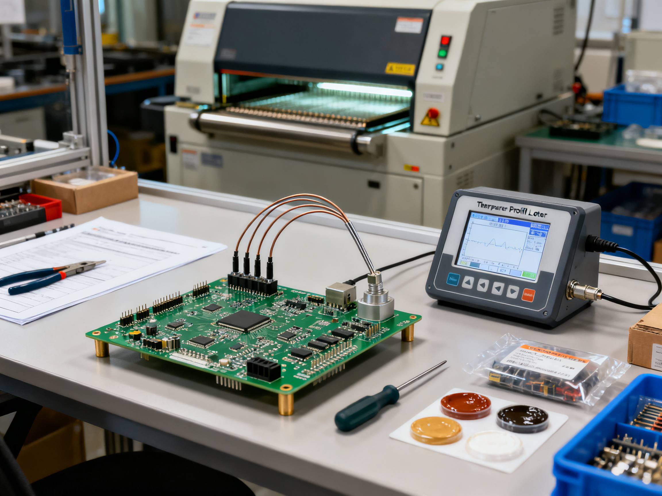
For reflow profiling, attach thermocouples to the thermal extremes of your populated board. Measure the actual profile on the production assembly, not a bare board. Confirm that your coldest and hottest measurement points stay within the overlapping limits of your paste, components, and board.
Recurring Defects and Their Real Causes
Defects do not appear randomly. They follow patterns that point to specific causes.
Insufficient paste usually traces back to aperture issues, poor release, or paste that is too cold or aged. Bridging typically comes from excess paste, registration drift, or gasketing failures. Tombstoning happens when wetting forces become unbalanced, often from pad asymmetry or component placement offset.
Head-in-pillow defects are particularly tricky. The issue often involves component warpage, insufficient flux, oxidation, or a profile that does not bring the package and paste together properly. A thermal camera or cross-section during process qualification helps confirm the actual mechanism.
Voiding under BGAs and QFNs relates to trapped volatiles, flux entrapment, pad geometry, or thermal conditions that do not allow proper outgassing. X-ray inspection catches these defects because they hide under the package where AOI cannot see.
Pro Insight: We worked a case where a BGA facility was seeing recurring head-in-pillow defects on automotive boards. The paste was fine. The placement looked good. What nobody checked was component body temperature during handling and placement. Turns out components were sitting in a cool staging area, then getting placed on a board that had already been warmed by the printing process. The thermal shock created enough warp to break the paste joint before it fully reflowed. Fixed the component preconditioning step and the HIP defects disappeared. The lesson? Sometimes the root cause has nothing to do with the machine that made the defect.
Process Control Table
| Process Stage | Critical Parameter | Measurement Method | Warning Limit | Reaction Plan |
|————–|——————-|——————-|—————|—————|
| Paste conditioning | Temperature, open time | Thermometer, timer | Outside spec range | Hold, re-verify |
| Stencil print | Volume, offset | 3D SPI | 2 sigma drift | Clean, adjust printer |
| Component placement | X/Y accuracy, rotation | AOI, placement verification | Out of tolerance | Check feeder, nozzle, program |
| Reflow profile | Peak temp, time above liquidus | Thermocouple, profiler | Exceeds component limits | Reprofile, check oven performance |
The Closed-Loop That Makes It Work
The strongest process control works in a loop. MSD control feeds paste handling. Paste handling feeds print quality. Print quality feeds SPI. SPI feeds the printer. Placement feeds reflow. Reflow feeds AOI and X-ray. And every inspection result should be capable of triggering upstream corrections.
That闭环 capability separates a reactive line from a controlled one. Without it, you are just hoping defects do not escape rather than preventing them from happening in the first place.
For thermal profiling, you want to see a representative profile chart that shows your zones, temperatures, and timing. A qualified profiling system captures this data and lets you compare it against paste and component limits side by side.
Building this process right from the start means fewer surprises when production volumes increase and changeover frequency goes up.
6. Install, Integrate, and Commission the Line
So you have ordered your equipment. Now comes the part that separates successful line installations from expensive floor decorations. Getting machines in the door is easy. Getting them to work together and hit production targets takes careful planning.
Site Readiness Before Equipment Arrives
Start with the basics nobody wants to think about until they become problems. Floor levelness matters more than most buyers realize. A reflow oven sitting on uneven concrete will track conveyor drift sideways for weeks before anyone figures out why. Electrical service needs to be sized for peak simultaneous demand, not the sum of individual machine nameplates. Network infrastructure should be tested and segmented before machines arrive, not debugged during commissioning.
Your receiving area needs to accommodate crate dimensions and the lifting equipment required to move heavy ovens and placement machines. Check door openings, elevator capacity, and the path from dock to final position. Sounds obvious, but we have seen lines delayed weeks because nobody measured before signing the purchase order.
The Commissioning Sequence
Once equipment arrives, follow a logical order. Rigging and placement come first, with careful attention to OEM-specified clearances for maintenance access. Utility connections follow: power, compressed air, exhaust, and nitrogen if your process requires it. Leveling and anchoring ensures machines stay aligned during production, especially for conveyors that span multiple pieces of equipment.
Calibration comes next. This means more than just running an auto-cal routine on the machine. Attach thermocouples to your reflow oven and verify zone uniformity across the full conveyor width. Check placement accuracy against known-good reference boards. Confirm SPI measurement accuracy against a calibrated artifact.
Software setup includes recipe migration, CAD data import, library building, and MES integration. Conveyor alignment between machines needs verification before boards start flowing. Operator training should happen in parallel with these steps, not after everything is supposedly complete.
FAT and SAT: Know What You Are Agreeing To
Factory Acceptance Testing proves the equipment works before it leaves the vendor. Site Acceptance Testing proves the installation works in your facility. Both need measurable criteria written into contracts, not vague promises about “satisfactory performance.”
Define acceptance tests around your actual products. Specify which board families, component packages, and production rates constitute a passing test. Include thermal profiling verification, placement accuracy by package type, SPI closed-loop performance, and traceability data integrity. Safety validation belongs here too, including guarding, emergency stops, and ESD controls.
Class A defects, meaning safety issues or fundamental functionality failures, should block final acceptance. Class B defects require documented owner and closure date. Nobody wins by accepting a line full of unresolved issues and hoping they sort themselves out.
A complete commissioning timeline typically spans four to eight weeks depending on line complexity. Budget time for punch-list resolution, repeat testing, and the inevitable discovery that something needs adjustment after initial runs.
Pilot Builds and Capability Studies
Before committing to production volumes, run pilot builds using your actual product mix. Capture baseline data for throughput, first-pass yield, and defect Pareto. A capability study on key parameters tells you whether the line is stable or just lucky.
Document deviations as they occur. Assign clear ownership for each one. Some issues belong to the equipment vendor. Others trace back to facility preparation. A few probably reflect assumptions that turned out to be wrong. Knowing the difference matters for resolution time and cost allocation.
Final Handover and Ongoing Support
Handover documentation should include calibrated measurement records, trained personnel with sign-off records, full machine backups tested for restore capability, preventive-maintenance schedules with required skills and parts, and a spare-parts list with recommended stock levels. Service response commitments need contractual clarity. What constitutes an acceptable response time for a critical stoppage versus a minor alarm?
The line is not yours until the documentation is complete and your team can run it independently. A vendor who walks away leaving you with undocumented recipes and untested backups has not really completed the job.
| Commissioning Phase | Key Activities | Typical Duration |
|——————-|—————-|——————|
| Site preparation | Floor, utilities, network, receiving | 2-4 weeks before delivery |
| Equipment installation | Rigging, placement, leveling, anchoring | 1-2 weeks |
| Utility connection | Power, air, exhaust, nitrogen | 1 week |
| Calibration | Thermal profiling, accuracy verification, SPI/AOI setup | 1-2 weeks |
| Software and integration | Recipes, MES, traceability, line communication | 1-2 weeks |
| FAT/SAT | Witnessed testing against acceptance criteria | 1-2 weeks |
| Pilot production | Capability studies, baseline data, deviation resolution | 2-4 weeks |
| Handover | Documentation, training, spare parts, support terms | 1 week |
Shenzhen Chuxin Electronic Equipment Co., Ltd. provides installation support and commissioning assistance for their SMT lines, including thermal profiling and process qualification services.
7. Control Quality, Traceability, Safety, and Compliance
So your line is commissioned and running pilot builds. Great. But now comes the part that separates a functioning line from a controlled one. Quality control, traceability, and compliance are not afterthoughts to add when something goes wrong. They are the systems that keep defects from reaching customers in the first place.
Build a Quality Plan That Covers the Whole Process
A solid quality plan starts before production and touches every step. Here is what that looks like in practice.
Incoming control means verifying components and materials before they hit the line. Check MSL labels, verify lot codes, and confirm materials match your approved vendor list. Paste and stencil management keeps your printing process stable. Track paste age, storage temperatures, and open time. Inspect stencils for damage or clogged apertures.
SPI, AOI, and X-ray inspection form your inline defense layer. SPI catches paste problems before placement. AOI finds visible defects after reflow. X-ray handles the hidden joints under BGAs and QFNs that AOI cannot see. Electrical testing validates functionality on boards that pass visual inspection.
Statistical process control gives you early warning before defects escape. Track your key measurements over time. When a trend starts drifting toward your control limits, you can react before making bad boards.
Nonconformance handling covers what happens when something goes wrong anyway. Document the defect, quarantine affected boards, investigate the root cause, and implement corrective action. Track your corrective actions to completion and verify they actually worked.
Traceability From Raw Material to Shipment
Traceability in 2026 means knowing exactly what happened to every board. Your IPC-1782 framework should capture board identity, component lots, machine programs, operators, process measurements, inspection images, rework records, and final disposition.
Board-level traceability links a serial number to everything that happened during assembly. Component-level traceability ties individual placements back to specific feeder positions, lot codes, and timestamps. If a customer calls with a field failure, you need to reconstruct the full genealogy quickly.
Automotive customers typically require serialized genealogy with complete machine and operator records. Aerospace and military contracts go even further, demanding approved-source documentation and configuration history. Consumer electronics often work with lot-level traceability, but this varies by customer.
Safety and Compliance Cannot Be Generic
Safety requirements depend entirely on your location, your products, and your industry. Machinery safety, chemical exposure limits, fume extraction, hot surface warnings, ESD controls, lockout procedures, and environmental obligations all need review against the standards that actually apply to your situation.
In the United States, OSHA requirements form the baseline for workplace safety. In the European Union, CE marking and ATEX directives affect equipment and chemical handling. OSHA-equivalent rules and applicable chemical laws generally carry legal weight, while IPC and management standards typically become binding only when incorporated into contracts or customer specifications.
Cybersecurity is increasingly relevant for connected production lines. Your MES and machine communication systems need proper access controls, data retention policies, and network segmentation. This is not optional anymore.
Data retention periods vary by sector and jurisdictions. Automotive records may need retention for the vehicle service life plus additional years. Aerospace requirements often extend decades. Consumer electronics traceability might only need to cover the warranty period. There is no universal answer here.
Quality KPIs That Actually Matter
Track metrics that drive decisions, not just metrics that look good on reports.
| KPI | What It Tells You | Typical Target Range |
|—–|——————|———————|
| First-pass yield | Overall process health | 95-99% for mature production |
| DPMO | Defect rate normalized | Benchmark against your own baseline |
| Cpk | Process capability | 1.33 minimum; 1.67 for critical processes |
| Changeover time | Flexibility | Measure from last good unit A to first good unit B |
| Downtime | Equipment reliability | Track planned versus unplanned separately |
| Scrap cost | Material waste | Percentage of production value |
Standards Matrix: Verify Before You Trust
Different industries reference different standards. Automotive work often involves IATF 16949 and customer-specific requirements. Aerospace leans on AS9100 and NADCAP. Military and defense have their own specifications that vary by contract.
IPC standards like J-STD-001, IPC-A-610, and IPC-1782 apply broadly across electronics manufacturing. But the exact revision matters. IPC-A-610 Revision J came out in March 2024, and standards continue to evolve. Check what revision is actually current for your contracts before assuming a particular version applies.
Compliance Disclaimer: The information in this guide provides general guidance only. Your specific compliance obligations depend on your product jurisdiction, applicable regulations, customer contracts, and adopted standard revisions. Consult qualified safety, legal, and quality professionals familiar with your specific situation before making compliance decisions.
Shenzhen Chuxin Electronic Equipment Co., Ltd. supports traceability integration with their SMT line systems, including MES connectivity and inspection data retention for quality documentation.
8. Budget, Scale, and Improve the SMT Line
Getting an SMT line installed is one thing. Making sure it pays for itself over five years is another story entirely. Too many buyers focus on the purchase price, sign the order, and then get surprised by the costs that follow.
The Real Total Cost of Ownership
Here is what you need to account for from day one. Equipment purchase is just the starting point. Installation, rigging, and facility modifications often run 15 to 30 percent of equipment cost. Feeders, nozzles, stencils, tooling, and support equipment add another significant chunk. Software licenses, MES integration, and traceability systems do not come free.
Then there are the ongoing costs. Utilities can be substantial for a reflow oven running at 200-plus degrees. Consumables like solder paste, flux, and nitrogen add up fast at scale. Labor for operators, technicians, and engineers matters. Maintenance contracts and spare parts need budgeting. And do not forget downtime. An hour of unplanned stoppage on a high-volume line costs more than most people expect.
TCO Formula:
Five-Year TCO = Equipment + Installation + Tooling + Utilities + Software + Training + Consumables + Maintenance + Energy + Labor + Downtime Cost + Service – Residual Value
The numbers tell the story. Research suggests purchase price represents only 35 to 60 percent of total lifecycle cost. Annual maintenance often runs 10 to 20 percent of original equipment value. Size your budget accordingly.
Three Line Scenarios Compared
| Factor | Small/Compact Line | Flexible High-Mix Line | High-Volume Line |
|——–|——————-|———————-|——————|
| Typical investment | $150,000 – $300,000 | $400,000 – $800,000 | $800,000 – $3M+ |
| Best for | NPI, prototypes, low-volume | Mixed products, frequent changeovers | Stable high-volume demand |
| Throughput range | 5,000 – 15,000 CPH | 15,000 – 40,000 CPH | 40,000 – 100,000+ CPH |
| Changeover time | Moderate | Critical metric | Scheduled downtime |
| Inspection level | Basic AOI | SPI + AOI | Full SPI, AOI, X-ray |
| Risk profile | Lower capital, higher unit cost | Balanced flexibility | High capital, low unit cost |
The right choice depends on your product complexity, business risk, and volume stability. A flexible high-mix line often delivers more value than chasing headline speed you do not actually need.
Building Your Continuous-Improvement Roadmap
Once the line runs, track these metrics monthly. OEE tells you how much productive time you actually get. First-pass yield shows whether defects are happening or being caught. Changeover time reveals whether your flexibility is costing you too much. Process capability (Cpk) tells you whether your process is stable or just lucky.
Year one focus: stabilize operations, train teams, capture baseline data. Year two: close inspection loops, reduce changeover time using SMED principles, optimize reflow profiles. Year three: add predictive maintenance, expand capacity with measured justification, evaluate automation where labor costs climb.
From Our Experience: Before signing any purchase order, verify what the quote actually includes. We have seen buyers budget $500,000 for a line, then discover they needed $150,000 more for feeders, integration, training, and first-year spares. Get the full scope in writing. Ask for a trial using your actual boards. And always model your cost per good board under conservative, expected, and upside scenarios before committing.
A procurement scorecard helps separate must-haves from nice-to-haves. Mandatory requirements cover your product specs, quality targets, and safety needs. Weighted preferences cover throughput headroom, service response, and upgrade paths that protect your investment long-term.
Shenzhen Chuxin Electronic Equipment Co., Ltd. provides investment consultation and TCO modeling support for SMT line planning, including capacity scenarios and continuous-improvement roadmapping.
Conclusion: Turn the Line Plan Into an Executable Specification
Planning an SMT production line in 2026 means following a sequence that actually works. Start by defining what you build and how much of it. Then specify the process you need, select equipment that matches those requirements, validate your layout and utilities, commission against clear measurable criteria, and finally improve using real production data.
That sequence matters. Skipping steps or doing them in the wrong order is where projects blow up and budgets disappear.
Role-Specific Next Steps Before Issuing RFQs
Production leaders: Confirm your takt time targets, changeover frequency, and uptime assumptions. These drive every equipment decision downstream.
Process engineers: Finalize your component package range, paste specifications, and thermal profile requirements. Get these right before sending anything to vendors.
Procurement managers: Build your TCO model covering five years. Purchase price is only 35 to 60 percent of lifecycle cost.
Quality teams: Define your inspection strategy, DPMO targets, and traceability level. Know what AOI cannot see.
Facilities and IT: Audit your floor, utilities, network, and ESD controls. Site readiness delays cost more than equipment delays.
From Our Experience: Before signing any purchase order, verify what the quote actually includes. Check line integration compatibility, confirm process stability data from trials using your actual boards, require written service response commitments with escalation paths, and validate expansion capacity for at least one planned product family. These four checks separate lines that run smoothly for years from expensive floor decorations that eat maintenance budget.
Ten-Point Line Readiness Checklist
- Annual demand converted to takt time and panel count
- Component package range finalized with centroid files
- Process route documented including wave or selective solder
- Inspection strategy defined with AOI and X-ray coverage
- TCO model built with five-year operating costs
- Floor plan validated with utility capacities
- Network infrastructure tested and segmented
- ESD controls verified against ANSI/ESD S20.20
- FAT/SAT acceptance criteria written with measurable thresholds
- Pilot build plan designed with representative board mix
For a complete requirements template and downloadable procurement checklist, download our SMT manufacturing process PDF guide.
Need a vendor-neutral assessment of your line requirements or want to compare quotes against your actual product data? Reach out for a requirements review before you send anything to suppliers.
Shenzhen Chuxin Electronic Equipment Co., Ltd. provides investment consultation and TCO modeling support for SMT line planning, including capacity scenarios and continuous-improvement roadmapping.