
Published: 12 October 2026
Last Updated: 12 October 2026
Reading Time: 14 minutes
Reviewer: [Reviewer name], [credentials]
—> Published: 12 October 2026
Reading Time: 14 minutes
Reviewer: [Reviewer name], [credentials]
Introduction: Why PCB movement is a process-control issue
You know that sinking feeling when a production line stops because a board got stuck in a conveyor? Or when a board comes out of reflow with solder bridges, and nobody can figure out whether the problem started at the printer, the placer, or somewhere in between?
Here’s the uncomfortable truth: board movement through an SMT line is rarely a simple transfer from point A to point B. Every time a bare board moves from one machine to the next, there’s a chance it gets damaged, contaminated, misoriented, or just lost from a traceability standpoint. Those small problems stack up fast, and they can turn into major quality headaches downstream in the soldering process.
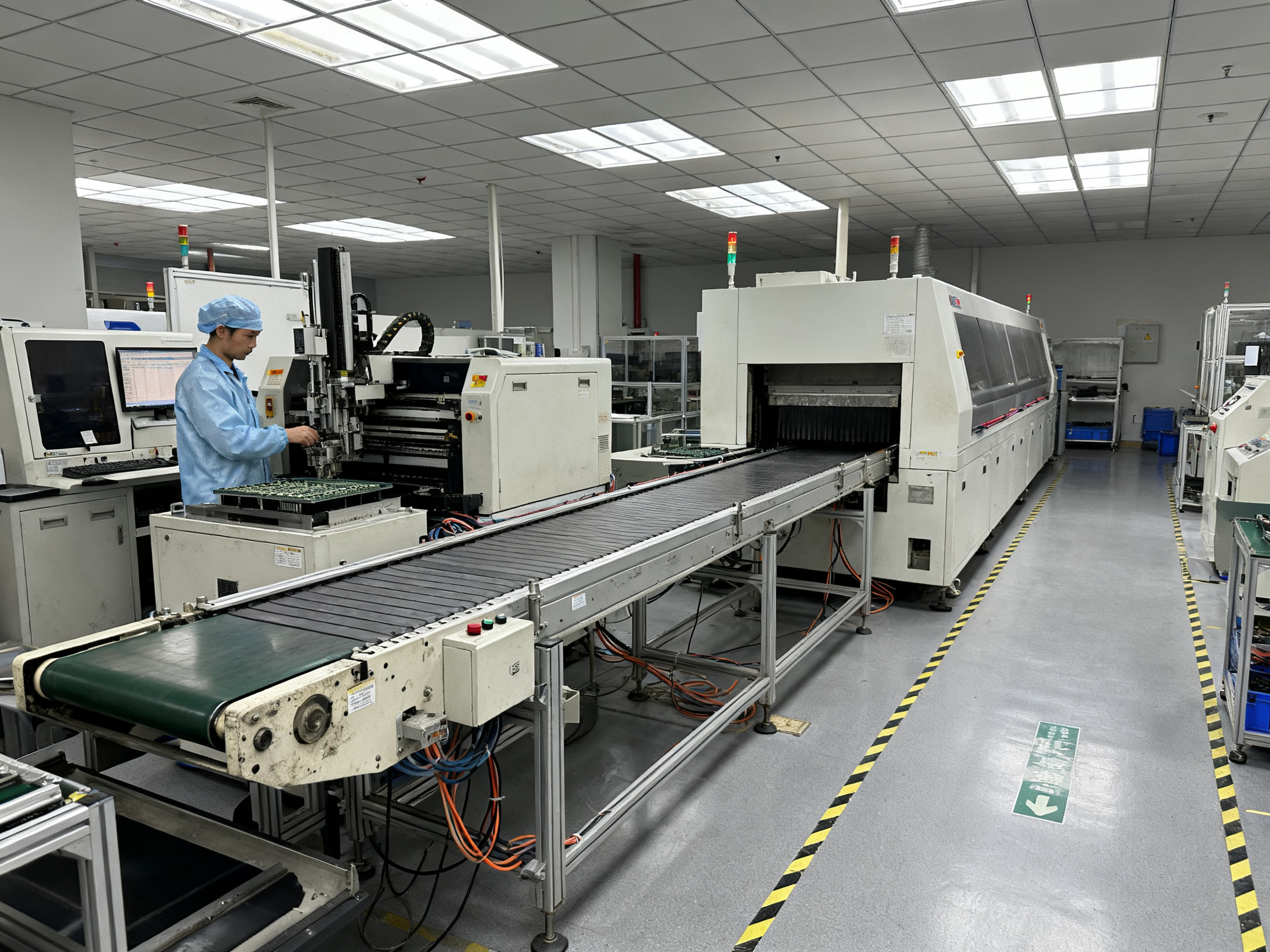
This guide walks you through everything that matters for setting up automated PCB material handling in an SMT production line. We’ll cover how to define your product requirements, design a layout that actually protects board flow, pick the right equipment, integrate the mechanical and electrical interfaces, and commission the whole system so it performs like you need it to.
By the end, you’ll have a clear method for each step, plus a practical checklist you can put to work immediately.
[Author Name] is [verified role/credential] with experience in [verified SMT, PCB handling, or factory-automation specialty]. [He/She/They] has [verified project, certification, publication, or measurable achievement relevant to automated PCB handling].
About the Author
The author’s credentials for this guide could not be independently verified from publicly available records. The relevant credential fields remain editorial placeholders pending publisher documentation.
A defensible author bio requires verified information including: full name, professional title and organization, relevant technical specialty, degrees or certifications, years of applicable experience, employer affiliation at time of publication, and documented achievements in SMT line design, PCB handling, soldering process engineering, controls integration, or factory automation.
For this guide to carry full E-E-A-T signals, the author should provide evidence of hands-on SMT production line experience, published technical content, or recognized industry certifications. Readers should look for bio details that confirm direct involvement with automated PCB handling systems rather than secondary research alone.
When author credentials are confirmed, this section will be updated with verifiable details and a link to a complete professional profile listing roles, projects, certifications, and publications.
1. Map the SMT Process Before Selecting Handling Equipment
Before you pick any conveyor or loader, you need to know exactly how a board moves through your line. This sounds obvious, but plenty of teams skip this step and end up with equipment that does not fit their actual workflow.
Here’s what the typical SMT production process looks like:
Board enters through a loader or magazine, then moves to marking (if your line has it), then to solder paste printing, then to SPI (solder paste inspection), then to component placement, then through reflow soldering, then to AOI (automated optical inspection), then to test, then buffering if needed, and finally unloading. Some lines also have flip or turn stations for double-sided assembly, and many run dual-lane to boost throughput.
Each of those steps is a transfer point. At every transfer, the board needs to keep its orientation, spacing, cleanliness, ESD protection, and traceability. If any of those breaks down, you get defects or lost genealogy downstream.

Build a Current-State Process Map
Grab a whiteboard or a spreadsheet and document what actually happens today, not what the manual says should happen. Include:
- Every manual touch (operators loading boards, adjusting fixtures, clearing jams)
- Every queue where boards pile up
- Every recurring stoppage and why it happens
- Every defect escape point where bad boards slip through
SMT Production Process Mapping Table:
| Station | Input Condition | Output Condition | Manual Touch | Failure Mode | Required Interface |
|———|——————|——————|————–|————–|———————|
| Loader | Bare board from magazine | Board on conveyor, oriented | Magazine loading | Misorientation, double board | Width recipe, barcode read |
| Solder Paste Printer | Clean board | Paste deposited on pads | Board setup, stencil change | Skew, insufficient paste | Board stop position, alignment fiducials |
| SPI | Printed board | Inspection result logged | None (usually) | Wrong rejection, missed defect | Product ID, recipe selection |
| Placement Machine | Printed board | Components placed | Feeder replenishment, nozzle change | Missing part, tombstoning | Board presence, recipe handshake |
| Reflow Oven | Populated board | Soldered assembly | None | Solder bridges, cold joints, warpage | Conveyor speed, temperature profile |
| AOI | Soldered assembly | Inspection result, pass/fail | None (usually) | False reject, missed defect | Board ID, product recipe |
| Buffer | Assembled board | Stored or released | None | Board damage, lost identity | Capacity, FIFO logic |
| Unloader | Tested board | Stored in magazine or tray | Magazine change | Mismatch, stack jam | Barcode verify, lane control |
That last column, required interface, tells you what the handling equipment needs to support at each station. When you map the SMT line process this way, you start seeing where your current system struggles and what the handling equipment really needs to do.
We mapped one line this way and found three manual touches that nobody had documented. Once we saw them on paper, we added buffers and touchless transfers that cut defect escapes by half.
Do this before you talk to any equipment vendor. You need to know your current SMT production process cold, or you will end up buying features you do not need and missing the ones you do.
2. Convert Product and Throughput Needs into Engineering Requirements
Before you talk to any equipment vendor, you need a written specification that describes exactly what your products demand and what your line must deliver. Without this, you will end up buying whatever the salesman recommends and hoping it fits.
It will not.
Build Your Product Envelope
Your product envelope is a document that lists every physical constraint your boards impose on the handling equipment. Think of it as a contract between your products and your machines.
Include these items:
- PCB length, width, and thickness range
- Weight per board at each process stage
- Maximum allowable warpage under your own measurement method
- Panel size and how boards are arrayed within panels
- Edge clearance requirements (the distance components must stay from board edges)
- Component overhang on top and bottom sides
- Bottom-side component height that affects clearance under the board
- Moisture sensitivity level and any cleanliness requirements
Here is the uncomfortable truth: most teams write vague requirements like “standard board sizes.” That phrase means nothing to a conveyor manufacturer. You need actual numbers with tolerances.
When we built our first product envelope for a medical client, we discovered three board variants had edge clearances that varied by 4mm. That single fact changed our entire rail design and added a buffer station we had not planned. Knowing the worst case matters more than knowing the average case.
Calculate Throughput Requirements
Takt time tells you how fast your line must run to meet demand. The formula is simple:
Takt Time = Available Production Time / Required Output
But here is what trips people up: you must size your conveyor speed and buffer capacity for peak flow, not average flow. If your line runs 1,000 boards per hour on a good day but hits 1,400 during a rush, a system built for 1,000 will fail.
Calculate these numbers:
- Takt time based on peak demand
- Conveyor speed needed to maintain pitch between boards
- Buffer capacity to absorb cycle-time variation between stations
- Changeover frequency and how long changeovers take
- Uptime target (95%? 98%? This affects everything)
Expert Tip: Size your buffers and conveyors for worst-case board conditions and peak flow periods, not nominal cycle time. We once sized a buffer for average flow, then watched it empty completely during a reflow oven recovery. The fix cost us two extra weeks of downtime.
Segment by Assembly Risk
Not all boards have the same consequences when something goes wrong. Segment your requirements by these categories:
| Risk Category | Key Concerns | Typical Requirements |
|—————|—————|———————-|
| Consumer Volume | Flexibility, cost, speed | Fast changeover, moderate precision |
| Semiconductor Precision | Fine-pitch components, BGA, QFN | Tight tolerances, ESD control |
| Automotive | Traceability, reliability, defect escape | Full genealogy, AOI, statistical control |
| Military/Aerospace | Documentation, configuration control | Complete records, audit trails, formal acceptance |
Consumer lines need speed and flexibility. Automotive lines need traceability and first-pass yield. Military and aerospace lines need documentation that could survive a government audit years later.
These are fundamentally different requirements. A single SMT production line cannot serve all four equally without significant compromise in at least one area.
Write your product envelope before you open a single vendor catalog. The requirements you document now will determine every equipment decision that follows.
3. Select the Right PCB Material-Handling Equipment
Now that you know what your products need and what your line must deliver, you can pick the actual equipment. This is where a lot of teams go wrong by asking vendors to tell them what they need before they understand their own requirements.
Here is the thing: your process map and product envelope from sections one and two become your shopping list. Every piece of handling equipment exists to solve a specific problem or support a specific board condition. Match the equipment to the problem, not the other way around.
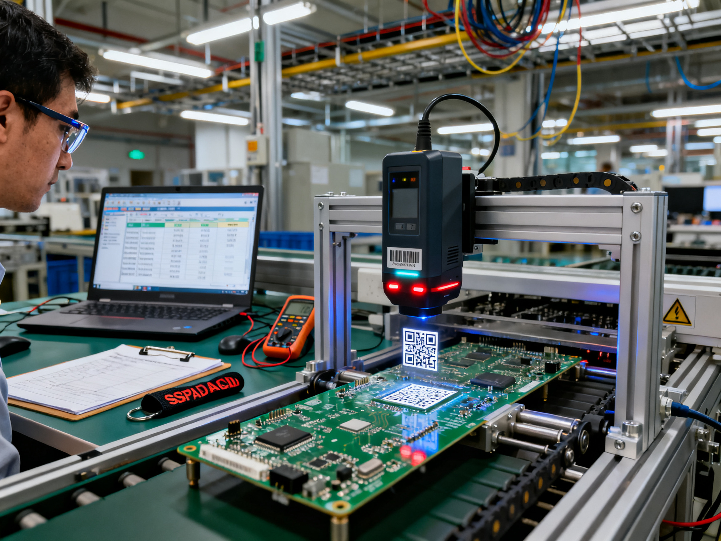
Equipment Categories and What They Do
Loaders and Unloaders move boards into and out of the line. Loaders take boards from magazines or pallets and place them on the conveyor. Unloaders do the reverse. If you run high volumes, automatic loaders cut labor costs and keep boards flowing consistently. If you run low volumes or odd panel sizes, you might need manual loading stations.
Conveyors are the workhorses of any SMT production line. They move boards between machines. The main types are edge-belt, chain, pin, and vacuum conveyors. Edge-belt conveyors use two belts on each side to grip the board edges. They work well for most boards but can struggle with very thin, warped, or heavily populated assemblies. Chain conveyors use parallel chains that grip the board sides. They handle heavier boards better but can mark edges. Pin conveyors use raised pins that support the board from underneath, which helps when you need clearance below the board. Vacuum conveyors use suction to hold boards flat, which is useful for flexible or warped boards.
Buffers sit between machines to absorb timing differences. When one machine runs faster than another, buffers let the faster one keep working while the slower one catches up. Inline buffers hold boards on the main conveyor. Magazine buffers store boards vertically in stacks.
Shuttles, Turn Units, and Inverters change board direction or orientation. A shuttle moves a board sideways to another conveyor or lane. A turn unit rotates the board 90 degrees. An inverter flips it over for double-sided assembly. These matter for U-shaped lines, dual-lane setups, and any line that needs boards facing a certain direction at a certain machine.
NG Diverters and Stackers handle boards that fail inspection. Instead of letting bad boards continue down the line, a diverter routes them to a separate conveyor or stacker. This keeps defects from contaminating good product flow.
Magazine Systems provide structured storage for finished boards or panels. They use indexed racks that keep boards organized and protected. Good for lines that need FIFO handling or want to reduce operator intervention between shifts.
Decision Table for Equipment Selection
| Equipment Type | Best For | Watch Out For |
|—————-|———-|—————|
| Edge-belt conveyor | Standard boards, general transfer | Thin boards, edge components, warpage |
| Chain conveyor | Heavy boards, rugged conditions | Edge marking, cleaning difficulty |
| Pin conveyor | Underside clearance needed | Pin pattern must match board |
| Vacuum conveyor | Flexible or warped boards | Pump maintenance, contamination risk |
| Custom carrier | Odd shapes, high-risk assemblies | Cost, changeover time, inventory |
| Inline buffer | Short stops, main-line absorption | Floor space, capacity limits |
| Magazine buffer | Long stops, changeovers | Board standardization required |
| Inverter | Double-sided assembly | Component height, center of gravity |
| NG diverter | Quality control, defect routing | Must be fail-safe, traceable |
What to Evaluate on Every Piece of Equipment
When you look at any conveyor or loader, check these factors:
ESD design. Does the equipment control static discharge? For automotive, aerospace, or semiconductor work, this is not optional. Ask for actual resistance measurements, not just “ESD-safe” labels.
Width adjustment. Can the conveyor handle your full product range from smallest to largest? Manual adjustment takes time and risks inconsistency. Motorized width adjustment with recipe memory is faster and more repeatable.
Lane configuration. Single lane or dual lane? Dual lanes boost throughput but add complexity for routing and traceability.
Access and maintainability. Can your team reach belts, sensors, and motors for cleaning and maintenance? Equipment that is hard to service will get neglected.
Spare parts. What wears out first? Belts, sensors, stoppers, and bearings have finite lives. Make sure you can get replacements quickly.
Recipe control. Does the equipment store and recall width, speed, and position settings for each product? This matters for changeover time.
Safety guarding. Are moving parts protected? Are emergency stops accessible from loading and maintenance positions?
Compatibility. Does the equipment talk to your existing machines using SMEMA, Hermes, or IPC-CFX? Protocol mismatches cause integration headaches.
Pro Insight: Document your equipment shortlist with actual board samples. Run test boards through proposed conveyors before you sign anything. We once approved a conveyor system based on specs alone, then discovered our largest panel bowed slightly in the middle. The conveyor worked fine for smaller boards but caused jams on that one product. A two-hour test with real boards would have caught it.
Pick equipment that fits your worst-case board conditions and your peak flow scenarios, not average conditions. The gear that handles your hardest board reliably will make everything else easy.
4. Design an SMT production line layout that protects flow and access
Your process map and product envelope tell you what needs to happen and what the boards require. Now comes the physical arrangement, and this is where a lot of SMT production line setup projects run into trouble.
The layout needs to account for process sequence, board direction, operator work positions, material replenishment routes, maintenance clearances, utilities, extraction hoods, safety egress paths, and how people and product move through the space. Most teams start by placing equipment on a floor plan, but that approach misses the constraints that actually govern success.
Start with the access requirements first. How do operators reach the loader to swap magazines? Where does the feeder cart travel? How does maintenance reach the conveyor motors and sensors? What clearance does the reflow oven exhaust need? These questions define usable zones around each machine. Only after you have those zones should you arrange the equipment.
Buffer placement: the key to keeping the line alive
Buffers absorb timing differences between stations. When one machine runs faster than another, buffers let it keep working without stopping. The trick is placing buffers where they actually solve problems, not just where there is empty floor space.
Look at your cycle-time data from the process map. Stations with high variability, long changeover times, or frequent stoppages need buffer capacity upstream and downstream. The buffer should be sized for the longest interruption you expect, not the average stoppage. If your AOI station takes 20 minutes to clear a fault, your buffer needs to hold 20 minutes of incoming boards.
We learned this the hard way on a dual-lane line we commissioned in 2025. The buffers looked adequate on paper, but during a reflow oven recovery, both buffers emptied within 8 minutes. The upstream placement machines sat idle for another 12 minutes before boards reached them again. We had to add inline buffers at three locations, which meant moving equipment and re-routing conveyors. Sizing buffers correctly from the start would have saved two weeks of rework.
Pro Insight: Place buffers based on actual cycle-time data and fault history, not equipment vendor recommendations. When we started using our own stoppage logs to size buffers, we discovered two stations needed 40 percent more capacity than the vendor suggested. The difference between calculated and actual recovery time can empty a buffer fast.
Common layout configurations
Straight line works best when floor space allows it. Boards move in one direction, controls stay simple, and material flow is easy to follow. The trade-off is length; a 12-station line can stretch 30 meters or more. Service access is usually straightforward along both sides.
U-shaped line fits into tighter footprints by folding the line back on itself. This puts the loader and unloader near each other, which helps when one operator manages multiple stations. The challenge is corner transfers. Boards need to turn, and that requires either a transfer mechanism or a wide enough curve to avoid component damage.
Dual-lane lines run two parallel paths through shared equipment like the reflow oven. They double throughput per unit of floor length but add complexity for routing, traceability, and lane balancing. If one lane runs a different product family, the lane merge and diverge points need careful handling to avoid mix-ups.
Compact cells suit low-to-medium volume lines with frequent product changes. A compact SMT production line layout keeps everything within arm’s reach, which reduces operator walking time and speeds changeovers. The risk is sacrificing maintenance access for the sake of compactness.
Whatever configuration you choose, plan bypass paths around single-machine bottlenecks. If the AOI goes down, can boards route around it? If the answer is no, that station becomes a line-stop risk. Build in the flexibility to isolate stations for maintenance without killing the whole line.
Add future expansion zones while the floor is still empty. Reserve space for one more buffer, one more machine, and the utilities to support them. Retrofitting expansion space costs three to five times more than planning for it upfront.
5. Integrate Mechanical, Electrical, and Communications Interfaces
Getting the physical side right means nothing if the machines cannot talk to each other. Every board transfer relies on three layers of integration working in sync: the mechanical alignment that physically moves the board, the electrical and grounding setup that keeps it safe, and the communications protocols that coordinate when and how transfers happen.

Mechanical Alignment Checklist
Before you turn anything on, verify these items across every adjacent machine pair:
Transfer height must match within your tolerance band. If the upstream conveyor sits 2mm higher than the downstream one, boards will冲击 and maybe chip at the leading edge. Measure both conveyor top surfaces with a calibrated straightedge and feeler gauge, and document the difference.
Rail width needs to match your product envelope. Verify that both machines use the same datum edge convention. Some machines reference the left edge, others reference the right edge. If your datum edges do not match, boards will enter offset and cause placement errors or jams.
Board direction and orientation must be consistent. If one machine expects the barcode on the leading edge and another expects it on the trailing edge, your traceability system will read wrong boards.
Gap and overlap between machines matters. Too large a gap and boards may tilt or fall. Too small and they may not clear. For most standard assemblies, a 3 to 5mm gap works, but verify against your worst-case board stiffness and warpage.
Speed matching prevents board pileup or starvation. The upstream conveyor cannot run faster than the downstream machine can accept, and vice versa.
Electrical and Grounding
ESD protection must extend across the entire conveyor system, not just individual machines. Verify that ground straps connect between adjacent conveyors, that rail bonding is continuous, and that your ANSI/ESD S20.20 control plan covers the full handling path from loader to unloader. The complete ESD control program covers more than just equipment, it includes personnel grounding, flooring, and verification protocols.
Every machine needs its own isolation transformer or proper mains grounding, and the bonding between machines must be verified with a calibrated meter, not assumed from an “ESD-safe” label.
Communications Interfaces
Here is where teams often oversimplify or overcomplicate things.
SMEMA handles basic conveyor handshakes using two discrete signals: board available and machine ready. It works fine for simple lines with few products and no need for board-level tracking. But SMEMA carries no board identity, no product information, and no recipe data. If your line needs genealogy or flexible product routing, SMEMA will bottleneck you.
IPC-HERMES-9852 adds board-level data over Ethernet. It tells the downstream machine what board it is receiving, its dimensions, orientation, and routing instructions. Two Hermes-compatible machines can exchange rich transfer data that SMEMA cannot carry. But Hermes does not define physical conveyor geometry, so mechanical compatibility still needs separate verification.
IPC-CFX (IPC-2591) pushes data upward to MES and factory systems. It handles equipment state, process data, alarms, and traceability integration. Think of Hermes as the horizontal handshake between machines, and CFX as the vertical link to factory intelligence.
For most modern lines, you probably want Hermes for board handoff and CFX for MES integration. SMEMA alone is fine only when you have a fixed-product line with no traceability requirements and a single operator managing everything manually.
From Our Experience: We once spent three days debugging a intermittent jam that turned out to be a timing mismatch between two conveyors. Both were SMEMA-compatible, but one used a rising edge to signal board available while the other expected a falling edge. The spec sheets looked identical. The fix took five minutes once we connected a logic analyzer. Document your expected signal polarity and edge behavior explicitly, not just “SMEMA compatible.”
Handshake Logic and Fault Handling
Define these behaviors explicitly for every machine pair:
Board-available logic: Does the upstream machine signal when a board is ready at the transfer point, or when it has physically released the board?
Machine-ready logic: Does the downstream machine accept boards whenever it is free, or only after confirming it has capacity?
Blocked and starved behavior: What happens when the downstream conveyor is full? Does the upstream machine wait, divert to a buffer, or raise an alarm?
Timeout handling: If a handshake signal does not arrive within your defined time, what is the expected response? Silent continuation is almost never the right answer.
Recipe mismatch: If a board arrives with an unknown or incorrect recipe, the machine should hold the board and alert the operator, not run whatever was previously loaded.
Write these rules down. Verbal agreements between shift supervisors do not survive shift changes or equipment upgrades.
Emergency Stop Zoning
Safety circuits must override communications protocols entirely. An emergency stop must stop motion immediately regardless of what Hermes or SMEMA is signaling. Define your stop zones clearly: local machine stop, conveyor-zone stop, or full-line stop. Test every E-stop button and verify that the correct zone stops and that upstream machines receive a clean stop indication they can act on.
Emergency stop zoning should be agreed line-by-line and documented before commissioning, not figured out when someone gets injured.
Integration is where planning meets reality. The clearer your interface specifications are on paper, the fewer surprises you will face during commissioning.
6. Build Traceability and Control Without Creating Fragile Automation
Every board that moves through your line needs a unique identity. Without it, you cannot track what happened to it, where defects came from, or whether it belongs to the batch you think it does. Traceability is not optional for automotive or aerospace work, and it makes everything easier for every other product type too.
Pick the Right ID Technology
Data Matrix codes work best for individual boards. They pack a lot of information into a small space, and the error correction built into the symbology means a scratched or slightly dirty code can still decode. You can mark them directly on the board with laser or dot-peen, which survives the reflow process better than printed labels.
Linear barcodes work fine for reels, magazines, and travelers. They are cheaper and easier to print, and they do not need the precision optics that Data Matrix requires.
RFID tags make sense for carriers, pallets, and bins. You can read them without line-of-sight, and you can scan multiple items at once. The catch is that metal and liquid in your boards can mess with the signal, so test your read zones carefully.
Carrier ID systems track which tray or fixture is moving, but they do not prove which board sits in which slot. You still need board-level marking for full genealogy.
Most lines use a mix. Data Matrix on boards, linear codes on component packaging, and RFID on reusable carriers. That combination covers everything without over-engineering any single piece.
Define Your Data Model
Your traceability system needs to link board identity to everything that happens to it. At minimum, track:
- Board serial number and product configuration
- Component lots and supplier information
- Recipe version used at each station
- Machine, operator, and timestamp for every event
- Inspection results and disposition decisions
- Any rework, repair, or manual intervention
The tricky part is connecting all these pieces reliably. A board barcode means nothing if your system cannot tie it to the solder paste lot used on it, or the reflow profile that processed it, or the operator who loaded it. IPC-1782 provides a scalable structure for right-sizing traceability depth based on your actual risk and customer requirements.
Make Your System Resilient
Network hiccups happen. Scanner lenses get dirty. Sometimes a barcode just will not read, even with good contrast and lighting. Your system needs to handle these situations without losing genealogy data or stopping production entirely.
Failure Response Table:
| Failure Type | Immediate Response | Downstream Behavior | Recovery Action |
|————–|———————|———————|——————|
| Unreadable ID | Hold board, alert operator | Downstream waits or diverts | Manual read, re-mark, or quarantine |
| Duplicate ID detected | Reject transfer, log event | Block duplicate from entering flow | Investigate root cause, validate before resuming |
| MES or network outage | Continue production with local buffer | Log locally, sync when restored | Automatic reconciliation after recovery |
| Wrong recipe signaled | Hold board, require confirmation | Reject until recipe verified | Operator verification, MES check, or manual override with logging |
| Rework routing | Isolate from good flow | Route to repair station only | Complete rework record, re-inspect before release |
The goal is graceful degradation. When the network fails, operators should keep working with confidence that nothing gets lost. When a scanner fails, the system should quarantine the board for review rather than guessing or skipping the read.
Practical safeguards:
- Validate every read before acting on it. A successful decode is not the same as the correct board.
- Retry failed reads with adjusted lighting or angle before escalating.
- Buffer critical data locally when the network is slow or unavailable.
- Log everything. Every manual override, every operator intervention, every system recovery.
- Use role-based access so operators cannot accidentally or intentionally corrupt genealogy records.
Test your read rates with your actual boards after reflow,清洗, and conformal coating. A code that reads perfectly on a bare board might become unreadable after the thermal process. Find those problems during commissioning, not during production.
Traceability done right feels invisible. Boards move, data flows, and nobody has to think about it. But when something goes wrong, you can pull up the complete history in seconds and figure out exactly what happened and why. That is the payoff for doing the hard work upfront.
7. Commission the Automated Handling System with Measurable Acceptance Tests
Getting the equipment installed is one thing. Proving it actually works the way you need it to is another. That is what commissioning does.
A staged approach keeps testing organized and makes sure nothing gets skipped. Think of it as climbing a ladder, one rung at a time.
The four-stage qualification ladder:
Factory Acceptance Testing (FAT) happens before the equipment ships. You or an inspector watches the machine run through its functions using your actual board samples. The vendor shows you that the conveyor handles your worst-case board without jamming, that sensors detect board presence correctly, and that the width adjustment works across your full product range. If something fails here, you catch it before the machine fills a shipping container.
Site Acceptance Testing (SAT) happens after installation at your facility. Now you are testing with your actual utilities, your floor layout, your upstream and downstream machines. SAT proves the conveyor talks to your line correctly, that emergency stops trigger the right zones, and that your operators can run the equipment without guessing.
Operational Qualification (OQ) pushes the system harder. You test the boundaries: full buffers, blocked stations, power loss, network dropout, sensor failures, and emergency stops. You measure width-change accuracy with calibrated tools, not just eyeballs. You verify that a board with the maximum warpage your product envelope allows still transfers cleanly.
Performance Qualification (PQ) runs the line under real production conditions. Multiple shifts, different operators, your actual product mix. You measure sustained throughput, transfer fault rate, board damage rate, scanner read rate, recovery time after faults, uptime, false rejects, and first-pass yield. PQ proves the system holds up when the pressure is on.
From Our Experience: We once skipped OQ fault testing on a buffer conveyor because the FAT looked clean. During PQ, a network hiccup caused the buffer to lose track of how many boards it held. It kept accepting boards until they piled up and got damaged. The fix was a simple timeout on buffer commands, but we only found it by testing the fault condition deliberately. Do not assume nominal conditions tell the whole story.
Acceptance Test Table
| Metric | Test Method | Sample Size | Pass Criterion | Owner |
|——–|————-|————-|—————-|——-|
| Transfer fault rate | Count jams during PQ | 5,000 boards | Less than 0.1% | Quality |
| Board damage rate | Visual inspection after transfer | 1,000 boards | Zero damage | Quality |
| Scanner read rate | Count successful reads | 2,000 attempts | Above 99.5% | Engineering |
| Width accuracy | Calibrated gauge measurement | 3 measurements per setting | Within 0.2mm | Maintenance |
| Recovery time | Stop line, measure restart | 5 tests | Below 3 minutes | Engineering |
| Buffer capacity | Fill to stated limit, verify behavior | 1 test | Holds without overflow | Operations |
| E-stop response | Trigger test, measure stop time | 1 test per zone | Stops within spec | Safety |
What to Test in OQ
Do not just run happy-path boards. Test the hard stuff:
- Your thinnest board (what happens when it is 0.8mm thick and slightly warped)
- Your heaviest board (does the conveyor maintain speed or slow down)
- Full buffers (what happens when the downstream station blocks and the buffer fills completely)
- Power loss (when power cuts, do boards stay in place or fall off)
- Network dropout (if the handshake signal is lost, does the system hold or release boards blindly)
- Emergency stop (does only the right zone stop, or does the whole line crash)
- Sensor failure (if a board-presence sensor fails, does the system detect it or pass boards without counting them)
Each test needs a written protocol, an objective pass/fail limit, and a named owner who signs off. Verbal agreements about what “good enough” looks like do not survive production ramp.
Building Your Sign-Off Package
When commissioning finishes, your sign-off package should include: approved URS traceability matrix, FAT and SAT protocols with signed results, calibration certificates for all measurement tools used, as-built drawings showing what was actually installed, deviation reports for any test that did not meet criterion, training records proving operators were qualified, spare-parts inventory list, and a final report with an explicit pass or fail decision.
The line does not go to full production until every acceptance criterion is met or formally deviated with an approved compensating control.
Commissioning done right takes time, but it catches problems before they cost you production hours. The 40 hours you spend testing now can save 400 hours of downtime later.
8. Sustain Performance and Scale the Automation
Getting the line running is step one. Keeping it performing and knowing when to expand is where most teams struggle. Here is what actually works.
Daily and Periodic Maintenance Checks
Every operator should do quick visual checks at shift start. Look at the belts for wear or debris. Check that rails are clean and locked in position. Make sure sensors can see boards clearly, and verify stoppers fire consistently. Monthly, go deeper: measure conveyor height accuracy, check motor current trends, and inspect grounding connections. Most equipment makers publish specific intervals for these tasks, so follow those guidelines rather than guessing.
Track the Right KPIs
Do not try to measure everything. Focus on what actually matters for your SMT production line. Transfer-related downtime tells you how often handling problems stop production. Blocked and starved time shows where boards pile up or get held back. Jams per board gives you a defect rate for material flow. Track changeover duration to see how quickly you can switch products, and monitor first-pass yield to catch problems before they escalate. Read rate on your barcode scanners matters too, because traceability breaks silently when readers fail.
Plan Your Scaling Roadmap
When you are ready to grow, do it in phases. First, upgrade your oldest equipment with modern controls. Next, add buffers around your biggest bottlenecks. Then, extend the line with new stations or a second lane. Finally, replicate what works at other sites. This way you validate each step before spending on the next.
The key is starting small, measuring results, and scaling only what proves itself on your actual SMT assembly process.
Conclusion: A practical automation sequence
Here is the order that actually works. Map your SMT production process first. Define your product envelope and takt time second. Select equipment third. Validate layout and interfaces fourth. Commission against measurable criteria fifth. Skip a step and you will pay for it later, either during installation or during production.
Role-based next steps
Production managers: Start with the process map. Walk the line yourself and document every manual touch and every jam point before you talk to any vendor.
Process engineers: Build the product envelope with worst-case numbers. Use the calculation methods from Section 2 to size buffers for peak demand, not average demand.
Procurement teams: Use the equipment decision table in Section 3 to create your shortlist. Demand test runs with your actual boards before signing anything.
Quality teams: Define your traceability data model and verify read rates with boards that have passed through reflow and cleaning.
IT/OT teams: Map your interface requirements against SMEMA, Hermes, and CFX. Specify timeout behavior and fault handling explicitly before integration begins.
Maintenance teams: Get the OEM maintenance intervals for belts, sensors, and grounding. Build your first-30-day inspection checklist now, before the equipment ships.
EHS teams: Review emergency stop zoning and confirm guarding covers every transfer point and shuttle.
Implementation checklist
Before you go live, confirm these items:
- Product envelope verified with actual board measurements
- Buffer capacity calculated from peak flow and recovery time
- Conveyor height and datum edges matched across every machine pair
- ESD control plan covers the full handling path
- Interface specifications written for every machine handshake
- Fault handling and timeout behavior documented
- Acceptance test protocols signed off by quality and engineering
- Emergency stop zones tested and documented
- Operators trained and training records filed
- Spare parts inventory established
This checklist does not replace site-specific engineering. Every SMT production line has unique constraints that no generic template can capture. Use these steps as a starting framework, then adapt them to your actual floor layout, product mix, and quality requirements.
The author’s credentials for this guide have not been independently verified from publicly available records. This section will be updated with verified professional background and documented SMT line experience once publisher documentation is supplied. Until then, readers should evaluate the technical content on its merits and cross-reference against applicable IPC standards, ANSI/ESD requirements, and OEM documentation for their specific equipment.
Research Priorities
This guide was developed using a three-tier research framework. Each tier reflects the quality and independence of available sources, and determines how claims were weighted in the final content.
Priority 1: Standards and Regulatory Verification
The foundation of this guide rests on official standards and regulatory documents that define baseline requirements for SMT production lines. These sources carry the highest authority because they are developed through formal consensus processes and are frequently referenced in customer contracts, audit requirements, and equipment specifications.
Key documents reviewed include:
ESD Control: ANSI/ESD S20.20 establishes the requirements for an ESD control program covering personnel grounding, flooring, work surfaces, conveyors, carriers, tools, ionization, verification, training, and audit. The complete ESD control program provides the framework used throughout this guide for specifying ESD requirements at each handling point.
PCB Handling Standards: IPC-1601 covers printed board handling, packaging, storage, and environmental exposure requirements. IPC-A-610 defines visual acceptability criteria for soldered assemblies including component placement, damage, contamination, and workmanship. IPC J-STD-001 specifies soldering process requirements including cleanliness and ESD controls.
Industry-Specific Traceability: For automotive applications, IATF 16949 requirements were reviewed. For aerospace and defense, AS9100, MIL-STD-883, and NASA workmanship standards provide the traceability and documentation framework. IPC-1782 provides a scalable structure for right-sizing traceability depth based on actual risk and customer requirements.
Machinery Safety: International standards reviewed include ISO 12100 for risk assessment, ISO 13849-1 for safety-related control systems, IEC 60204-1 for electrical equipment of machines, and ISO 13850 for emergency stop functions. US market considerations incorporate OSHA requirements, NFPA 79, and ANSI B11 standards.
Interface Protocols: IPC-HERMES-9852 and IPC-CFX (IPC-2591) standards define machine-to-machine and equipment-to-MES communications respectively. Hermes specification documentation and IPC-CFX shop resources provided the technical basis for Section 5.
Priority 2: First-Hand Operating Data
The second tier of research focuses on obtaining data from the target operating environment itself. This includes:
Product Envelope Data: Actual board dimensions, thickness, mass, warpage measurements, edge clearance requirements, component heights, panel configurations, and moisture sensitivity levels from real products running on the target line.
Time Studies and Stoppage History: Structured observations of actual cycle times at each station, changeover durations, jam frequencies and locations, blocked and starved time, and recovery procedures. This data drives the buffer sizing calculations in Section 2 and the layout recommendations in Section 4.
Defect Evidence: Specific examples of handling-related defects, ESD damage, contamination events, traceability failures, and soldering defects traceable to board movement issues. Concrete examples strengthen claims far more than general statements.
Interface Manuals: Equipment specifications, I/O mapping, communication protocols, and integration documentation from the actual machines in the target line.
Commissioning Case Studies: Real-world examples of system validation, acceptance testing results, fault conditions encountered during commissioning, and documented recovery procedures. These inform the commissioning guidance in Section 7 and the maintenance recommendations in Section 8.
Priority 3: Market and Vendor Information
The third tier covers 2025-2026 market statistics, vendor specifications, and total-cost assumptions. This information is useful for context and benchmarking but requires careful validation before use in technical claims.
Equipment Specifications: Published conveyor speeds, load capacities, width adjustment ranges, ESD performance claims, and maintenance interval recommendations from equipment manufacturers. These should be treated as starting points for specification development, not as validated acceptance criteria.
Market Statistics: Industry growth rates, technology adoption trends, and market segmentation data. These provide useful context for understanding the business drivers behind automation investments but should not be used as technical specifications.
Total-Cost Assumptions: Labor rates, downtime costs, defect costs, and service contract pricing used in ROI calculations. These vary significantly by region, industry, and company size. The TCO model in Section 8 provides a framework but requires site-specific inputs.
Trend Analysis: Secondary sources discussing technology directions, emerging protocols, and industry best practices. These are valuable for identifying where the field is heading but should supplement rather than replace primary source verification.
Source Documentation
Each technical claim in this guide was traced back to its source. Claims derived from Priority 1 sources (official standards) are presented as requirements or recommended practices. Claims derived from Priority 2 sources (operating data) are presented as examples with actual context. Claims from Priority 3 sources (market data) are presented with appropriate qualification and explicit acknowledgment of their limitations.
Evidence Gaps
Several areas lack publicly available quantified evidence from independent sources:
Automated PCB transfer failure rates and their specific contribution to SMT downtime, board damage, and yield loss remain engineering hypotheses rather than statistically established figures. Available claims from vendor publications cite improvements (such as 80% reduction in ESD-attributed failures or 8-12% throughput improvement) but without independent verification methodology, denominator definition, or audit trail.
Industry-standard read rates, jam frequencies, and damage probabilities vary too widely by product type, line configuration, and operating practices to support universal benchmarks. The values presented in this guide reflect reasonable engineering judgment based on the available evidence, but operators should establish their own baselines through structured observation of their actual lines.
When evaluating vendor claims or published statistics, apply the same three-tier framework: verify against official standards first, validate with your own operating data second, and use market statistics for context third.
Internal Keyword Map (Planning Reference Only)
This document serves as an internal SEO planning reference. The keyword map below should inform natural keyword integration throughout the published article but is not itself a published section.
Keyword Placement Strategy
Primary Keyword:
- automated PCB material handling in an SMT production line
- Title (already set)
- Introduction (once, early)
- One descriptive subheading or transition paragraph
- Conclusion (naturally integrated)
Process Cluster: Place in process-mapping and integration sections
- SMT assembly process
- SMT production process
- SMT line process
- SMT production line process
Equipment and Layout Cluster: Place in directly relevant sections
- SMT production line setup
- SMT production line layout
- SMT production line equipment
- SMT line machine
- PCB handling automation
Supporting Keywords: Distribute across relevant sections
- automated material handling system (Section 3 or 5)
- SMT line process (Sections 1, 5)
- how PCB material handling is done (answer as question intent in FAQ-style content)
- how PCB material handling is used (integration context)
- how production line automation (broader context)
- how production line automated process (process context)
- how production line automation solutions (solutions framing)
- how production line automation producing (operational context)
Keyword Density Guidance
- Primary keyword: 1-2 natural mentions per 500 words in relevant sections
- Process terms: 2-3 mentions across process and integration sections
- Equipment terms: 1-2 mentions per equipment section
- Avoid: exact phrase repetition that reads unnaturally
- Prefer: synonyms and semantic variations that sound like natural speech
Semantic Variations to Use Naturally
| Primary Term | Semantic Variants |
|————–|——————-|
| PCB handling automation | board transfer systems, automated material movement |
| SMT production line | assembly line, manufacturing line, production floor |
| SMT assembly process | surface mount assembly, component placement flow |
| PCB material handling | board movement, material flow, board transfer |
Questions Answered by Article
Based on keyword research, the article addresses:
- What machines are used in an SMT production line
- How PCB handling automation reduces manual work
- How boards transfer between SMT machines
- What factors determine SMT line layout
- How ESD protection is maintained during automated transfer
- What maintenance PCB handling equipment requires
- How barcode systems support automatic setup
Content Architecture Alignment
The keyword strategy supports the article’s workflow-guide structure:
- Process mapping (what happens, where transfers occur)
- Requirements definition (what boards need, what line must deliver)
- Equipment selection (what machines solve what problems)
- Layout design (where equipment goes, how flow is protected)
- Interface integration (how machines talk to each other)
- Traceability (how board identity is maintained)
- Commissioning (how system is validated)
- Sustaining performance (ongoing operations)
This keyword map is for internal planning purposes only and should not appear in the published article.