
About the Author
[Author Name] is a Senior SMT Process Engineer at S&M Co. Ltd. (Shenzhen Chuxin Electronic Equipment Co. Ltd.), where they lead process engineering for lead-free reflow ovens, wave soldering machines, and fully integrated SMT production lines. Their hands-on work covers defect reduction across BGA, QFN, and plated through hole assemblies, plus IEC and RoHS compliant process qualification for consumer electronics, semiconductor, and military builds.
This article was reviewed on 22 October 2026 by [Reviewer Name, Credentials]. All standards, materials, and process recommendations referenced here reflect current guidance as of 2026. Reviewer sign-off must be completed before this piece is published.
Visuals: author headshot, S&M Co. Ltd. logo, review date stamp, and a linked company project page.
What Is Through-Hole Soldering? Definition, Process, and Core Variants
So what is through hole soldering, in plain terms? It’s a joining process where component leads or pins pass straight through holes drilled in a PCB, then get locked in place with molten solder. The solder flows around the lead inside the hole, forming a joint on the top side, the bottom side, and ideally inside the barrel itself. The finished joint is mechanical as well as electrical, and that mechanical strength is the whole point.
Two structural families show up in every real assembly:
| Feature | Plated Through Hole (PTH) | Non-Plated Through Hole (NPTH) |
|—|—|—|
| Barrel finish | Copper or electroplated tin/silver/gold | Raw laminate, no plating |
| Electrical connection | Yes | No, mechanical or thermal only |
| Typical use | Connectors, relays, transformers, terminal blocks | Mounting holes, chassis grounding, alignment pins |
| Solder target | Top fillet, bottom fillet, full barrel | None, or a separate grounding lug |
Plated through hole soldering is the one that matters for signal and power. The plating is what the solder actually bonds to, so a stripped or contaminated barrel turns a good joint into a cold one in a hurry.
Why does this process still dominate so many builds in 2026? Strength, mostly. A soldered pin through a plated hole resists vibration, cable pull, insertion force, and thermal cycling far better than a surface mount pad. Add current handling, the ability to bolt a heat sink directly to a device, and the fact that a technician can desolder and replace the part in minutes, and the case for through hole becomes easy.
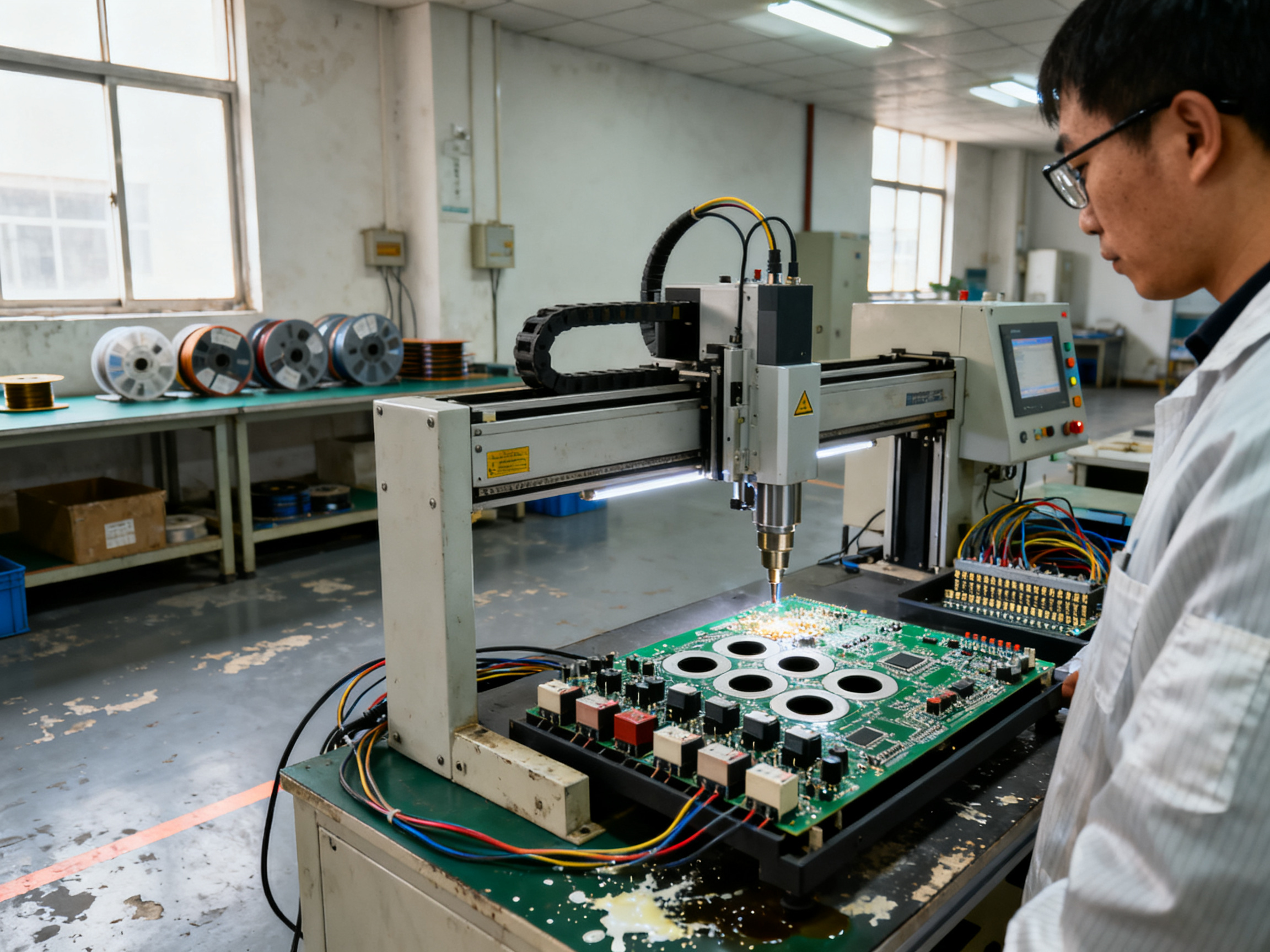
Those exact needs drive where through hole parts still show up: connectors and terminal blocks, relays, transformers, larger power inductors, big power resistors and capacitors, heat sink hardware, and press-fit interconnects in backplanes. Buying guides still describe the normal line sequence as SMT reflow first, then a downstream through hole operation for whatever’s left on the board, whether that means wave, selective, press-fit, or hand soldering (SMT vs through hole assembly guide).
And no, you can’t put a clean percentage on how many mixed boards still contain through hole parts. Public data covers process revenue, not board counts, so treat any headline figure as a vendor estimate rather than a measured fact.
Pro Tip: When a connector is mounted through a plated hole and also takes a mechanical screw or clip, treat the joint as a support feature, not just a solder feature. Check fillet shape and barrel coverage before you judge the joint quality.
Next up: the hands-on side of it, from hand soldering a single pin all the way to fully automated systems.
Surface Mount vs Through-Hole Soldering: A Method-by-Method Comparison
Let’s get straight to the point: surface mount and through hole aren’t competing processes so much as they are two answers to two different questions. Surface mount answers “how do I fit 2,000 parts onto a board?” Through hole answers “how do I make sure the connector survives being yanked out by a service tech?”
Surface mount wins on density. You can put parts a fraction of a millimetre apart, and a board that fits in your palm can hold a surprising amount of silicon. Through hole cannot compete on that. What it can do is survive punishment. A soldered pin through a plated hole holds against cable pull, insertion force, vibration, and thermal cycling in a way that a solder fillet on a pad simply cannot.
Then there’s cost. And this is where most comparison charts get sloppy, so here is the honest version.
| Factor | Surface mount (reflow) | Through hole (wave / selective / manual) |
|—|—|—|
| Parts per unit area | Very high, sub-millimetre pitch | Low, holes are 0.8 to 3.2 mm apart |
| Cost per joint at high volume | Low, placement is machine-driven | Low for wave on dense THT boards, high for manual |
| Cost per joint at low volume | High, setup and stencil costs dominate | Manual is cheaper below roughly 50 units |
| Typical defect modes | Tombstoning, bridging, insufficient paste, voiding | Insufficient fill, cold joints, blowholes, bridging, insufficient wetting |
| Repair in the field | Difficult, pad damage is common | Easy, part can be removed and replaced in minutes |
| Heat tolerance of joint | Good, no wave exposure | Good, but board sees full pot temperature |
| Board size limits | Limited by panel size and placement head travel | Limited by wave or nozzle geometry |
| Mechanical strength | Weak, relies on copper pad adhesion | Very strong, load carried by the barrel and the lead |
| Current handling | Needs large pads and copper pours | Large leads and barrels carry current well |
| Heat sink attachment | Awkward, usually a separate mechanical part | Natural, bolts straight to the board |
| Automation fit | Excellent with pick and place | Good with wave or selective, poor with hand |
| Process steps in a mixed line | Reflow | Insert, then wave, selective, or hand solder |
That table tells a story worth sitting with. Surface mount is a placement machine problem. Through hole is a thermal and wetting problem. Different failure modes, different root causes, different inspection criteria.
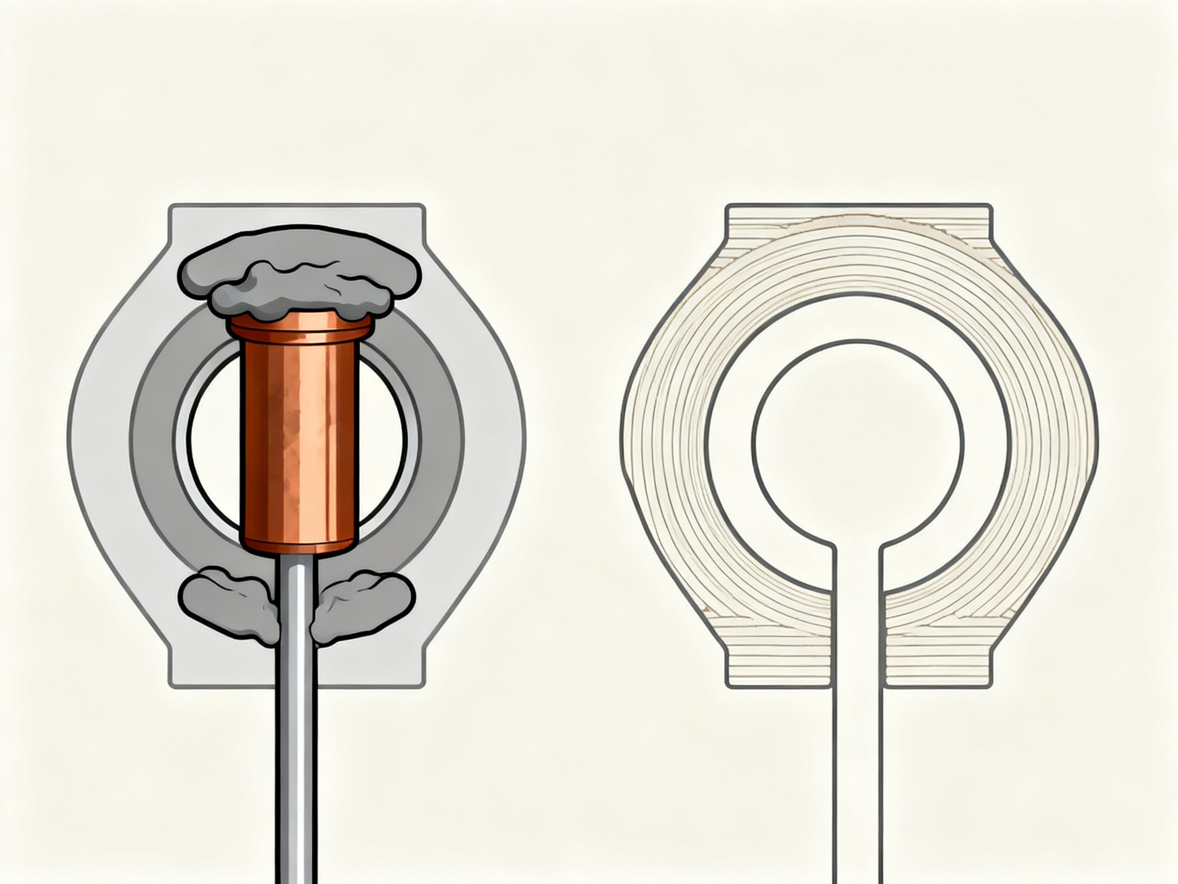
Now, the real comparison in 2026 is not SMT versus THT. It is process integration. Most lines run reflow for the dense side of the board, then take the same board through a downstream through hole operation for the connectors, relays, and power parts that were never placed by the reflow machine. As an EMS process guide from 2026 puts it, reflow is the foundation of SMT, wave soldering is the conventional method for serial THT production, and selective soldering is the method built for mixed SMT and THT boards (how to choose soldering technology in EMS).
So when someone asks which process is better, the useful answer depends on five things.
Volume. Above a few hundred units a month, wave or selective beats hand soldering on cost and consistency. Below that, hand soldering wins because fixtures and programming cost more than the labour you save.
Joint count per board. Two connectors? Hand solder. Forty through hole joints? Selective wave.
Thermal mass. Big transformers and power inductors soak up heat. That raises the preheat requirement and the dwell time, or you trap flux and get blowholes.
Mixed connector density. Dense SMT near through hole holes means full-board wave will bridge or float small parts. Selective gets you out of that.
First pass yield target. This is the number that decides equipment budgets. If your customer demands 99.5 percent first pass yield on mixed boards, hand soldering is not a process, it is a hope.
One caution on data here. You will see figures floating around claiming that surface mount accounts for roughly two thirds of PCB assembly revenue, and forecasts showing mixed-technology lines growing at over 5 percent a year through 2031. Both are real published numbers, but neither tells you what share of boards contain a through hole part. Revenue share is not board share, and a market forecast is not a production record. No defensible industry-wide percentage exists for how many mixed boards carry through hole components today. So treat any precise figure you find as a vendor estimate rather than a measured fact.
Where the through hole content concentrates is clear, though. Connectors, terminal blocks, and relays lead the list, because they take mechanical punishment. Press-fit interconnects dominate backplanes and high-pin-count industrial I/O. Transformers, power inductors, large power resistors, and big capacitors follow, since size, creepage, and current handling favor real leads. Heat sink hardware sits in the same family, more as a mechanical retention item than an electronic one. Industrial, automotive, aerospace, and defense products keep through hole parts for reasons of shock, vibration, and field serviceability that surface mount simply cannot match.
And when you look at defect rates side by side, the spread is wide. Manual soldering sits at the top of the range, driven by operator technique and inconsistent tip temperature. Dip soldering sits lower but carries its own risks, mainly preheating and floatation. Wave soldering sits well below both on dense THT boards. Selective wave soldering posts the lowest defect rate of the four on mixed-technology work, because it applies heat and solder only where they are needed.
That last point is the one that matters most for anyone planning a 2026 line upgrade.
Pro Tip: Judge the two processes on separate scorecards. Score SMT on placement accuracy and paste print quality. Score through hole on barrel wetting, fill percentage, and joint appearance. Mixing the criteria hides real problems in both.
Want the mechanical reasoning behind these numbers? The next section walks through through hole soldering techniques from the soldering iron all the way to fully automated systems, including why hand-soldered joints show up so often in warranty returns on mixed lines.