
Published: October 27, 2026
Last updated: October 27, 2026
Reading Time: 14 minutes
Written by: [Author name]
Reviewed by: [Reviewer name, credentials if supplied]
Editorial note: the author and reviewer fields are left as placeholders until names and credentials are supplied and fact-checked by the publication team. Technical claims, standard references, and profile data in this guide were checked against manufacturer documentation and the cited sources, and every numeric limit quoted is attributed to its source rather than presented as a universal rule.
Introduction: What SMT Heating Equipment Means and Why Its Construction Matters
Here is the part of the SMT line nobody films for marketing videos. A board goes into the oven, comes out looking fine, gets a green light from the AOI, and ships. Three weeks later the customer opens a BGA and finds a hollow joint that never had a proper fill. Nobody saw it happen, because the reflow oven is a closed box doing its work in the dark.
That is the whole reason to care about how SMT heating equipment is built.
So what is SMT heating equipment?
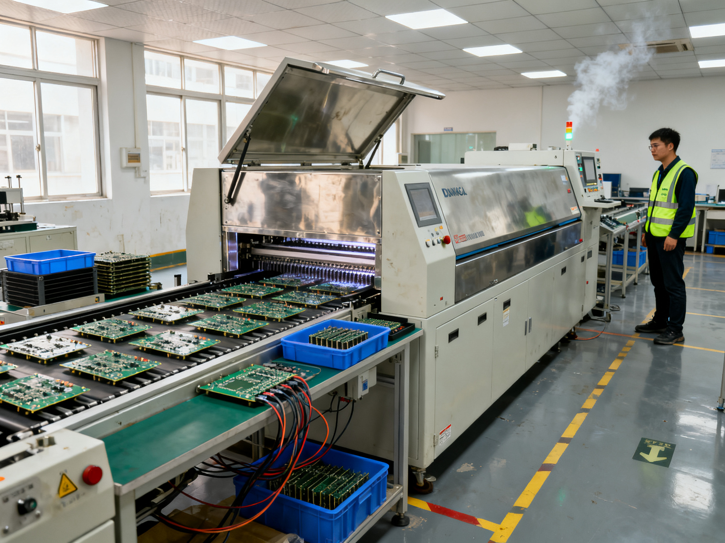
SMT heating equipment is the thermal machinery that heats, reflows, cools, and stabilizes soldered surface-mount assemblies. The reflow oven is the core of it. Inside, a conveyor carries a populated PCB through controlled zones that raise temperature, hold it, drive solder paste past its liquidus point, and then bring everything back down on a controlled ramp so the joint solidifies properly.
An industrial hot air oven typically ships with a conveyor or transport system, multiple independently controlled heating zones, one or more cooling zones, temperature sensors with closed-loop controls, exhaust and flux management, alarms, and recipe storage. Nitrogen capability is common where oxidation control matters. Some newer builds add profiling ports, connectivity to line software, and effluent capture.
Why construction matters more than the spec sheet
Solder joints only fail later if the thermal process drifts, and thermal process is the direct output of how the machine is put together. If airflow is uneven, a heavy copper region under a large BGA cooks hotter than the oven setpoint while a small part near the chamber edge runs cold. If the controller only regulates air temperature, you have no idea what the solder joint actually saw.
The process windows are narrow enough to notice. Indium’s SAC305 RMA-155 paste data sheet lists a recommended soak of 20 to 60 seconds and a recommended time above liquidus of 45 to 60 seconds, with peak temperatures around 230 to 260 C Indium RMA-155 paste processing guidance. Those numbers came from process development. Hit them consistently and you get repeatable joints. Miss them and you get graping, head-in-pillow, and cold solder.
And compliance is not optional. IPC/JEDEC J-STD-020 classifies surface-mount devices by moisture sensitivity and reflow exposure, so the component datasheet, not the oven recipe, sets the real ceiling.
What this guide covers
Frame and chamber construction. Heating zones and elements. Airflow and the hot air versus cold air debate. Temperature control and sensors. Conveyor and cooling design. Safety systems. Factory assembly through commissioning and validation. Plus how to evaluate an oven before you buy one.
Here is the deal: you cannot judge the machine until you understand the thermal process it has to deliver. So we start there.
Author note: the publication team has not yet supplied a verified author name and credentials for this guide. Technical claims, standard references, and profile figures were checked against manufacturer documentation and the cited sources, and every numeric limit is attributed to its source rather than presented as a universal rule.## About the Author
[Author Name] is pending verification] — This guide was written by a manufacturing engineer with hands-on SMT line experience, including work with lead-free reflow oven commissioning, thermal profiling, and defect reduction on BGA and QFN assemblies. Once the publication team verifies the author’s name, role, and credentials, this section will be updated with the specific equipment projects, production results, and standards experience that shaped the technical guidance above.
Editorial note: No author details were supplied in the source material for this piece, so a visible placeholder is used rather than invented credentials. Readers who need a named technical contact for the equipment covered here can reach the S&M Co. Ltd. team (Shenzhen Chuxin Electronic Equipment Co., Ltd.), who support lead-free reflow ovens, wave soldering systems, and full SMT production line integration for consumer electronics, semiconductor, and military assembly work.## 1. How a Reflow Oven Works: The Thermal Process Before the Hardware
Before we talk about sheet metal, elements, and fans, we need to talk about what the oven actually has to deliver: a specific temperature-versus-time curve at the solder joint. Everything else in the machine exists to serve that curve.
Here is the process in order.
Preheat brings the assembly up from ambient toward the paste’s activation range. The goal is gentle, because solder paste contains solvents and flux that need to evaporate and activate gradually. Slam the temperature too fast and you get skinning, spatter, and thermal shock on large thermal masses.
Soak holds or slowly raises the temperature through an intermediate band, usually around 140 to 160 C for SAC305 pastes. This is where the board and components equalize. If the board core is still cold when the surface is hot, you get uneven wetting later.
Reflow is the time above liquidus, the window where the alloy is fully molten. For SAC305 that liquidus sits at 217 C. The paste needs enough time here to melt, wet the pad and lead or ball, and coalesce into a solid joint.
Peak is the highest measured temperature at the monitored point, high enough to complete reflow but below the package limit.
Controlled cooling then brings everything down at a steady rate so the joint solidifies with a sound grain structure and low residual stress.
| Profile stage | What it controls | SAC305 reference range (Indium RMA-155) |
|—|—|—|
| Ramp rate | Heating speed from ambient to peak | 1.0 to 1.5 C/s recommended |
| Soak | Flux activation and thermal equalization | 140 to 160 C for 20 to 60 s recommended |
| Time above liquidus | Melting, wetting, joint coalescence | 45 to 60 s recommended |
| Peak temperature | Full reflow without exceeding package limits | 230 to 260 C recommended |
| Cooling rate | Solidification and grain structure | 2 to 6 C/s recommended |
Those figures come straight from the Indium RMA-155 SAC305 paste data sheet, and they are paste-specific starting windows, not universal limits. Standards such as IPC/JEDEC J-STD-020 classify packages by moisture and reflow sensitivity, but they do not hand you an oven recipe.
Now the part that trips up most buyers. A zone set to 240 C is a command to a heater, not a promise about your solder joint. A lightly loaded board edge and a heavy copper pour under a large BGA can sit in the same oven and see completely different thermal histories. Convection dominates, infrared adds radiant energy at the surface, board mass and copper area hold or shed heat, and component packages conduct it differently depending on their lead frames and thermal pads. Board mass, conveyor speed, zone setpoints, and paste alloy all push the product profile around at the same time.
That is why modern ovens often combine methods, adding infrared or nitrogen-assisted heating to shape the curve faster than convection alone can, and why profiling a representative populated board remains the only way to know what your parts really see.
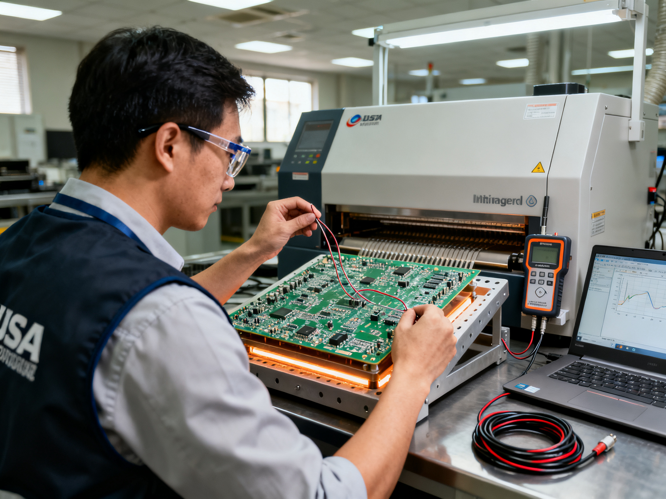
Expert Tip: Oven setpoint and actual component temperature are two different numbers, and only the second one matters for quality. A zone set to 240 C tells you what the controller asked the air to do. Compliance is judged on the temperature the component body actually experienced, measured with a thermocouple at the joint. Always profile populated boards before locking a recipe.## 2. The Mechanical Structure: Frame, Chamber, Insulation, and Access Panels
The heating and cooling parts get all the attention in a spec sheet, but the structure around them decides whether the machine holds temperature, survives a five-year shift schedule, and can be serviced without tearing the line apart.
Most industrial reflow ovens use a welded or modular steel frame, usually powder coated outside and lined inside with stainless steel. The frame carries the load of the conveyor, the heating modules, and the cooling sections, and it needs to stay rigid while the chamber runs at 250 C for eight hours a day. Modular construction, where sections bolt together, makes it easier to replace a damaged chamber or extend line length later. Welded construction gives tighter tolerances and fewer leak points.
The chamber is the stainless-steel box that actually holds the process air. Stainless is not decorative here. It resists flux residue, outgassing, and the repeated thermal cycling that cracks mild steel. Interior plenums distribute air across the width of the chamber, and they are usually removable so a technician can reach heaters, thermocouples, and fans without dismantling the whole oven.
Insulation is where a lot of buyers save money, and it shows up in your energy bill and your temperature stability. High-temperature ceramic fiber or calcium silicate blankets line the chamber walls, hood, and doors. Thermal breaks at door frames and cable entries stop the frame from becoming a heat sink. Good sealing keeps hot air in and keeps flux-laden exhaust out.
| Part | Typical material | What it must survive | Why it matters | Watch out for |
|—|—|—|—|—|
| Base frame | Welded or modular steel, powder coated | Structural load, vibration from conveyor motors | Misalignment shows up as belt tracking problems | Floor loading and leveling feet that actually adjust |
| Process chamber | 304 or 316 stainless steel | Flux residue, outgassing, thermal cycling | Corrosion pitting leaks heat and contaminates air | Weld seams around plenums and door frame |
| Insulation | Ceramic fiber or calcium silicate blankets | 250 C+ internal air, years of cycling | Lower heat loss, steadier zone control | Compressed or soaked blankets near the door |
| Seals and gaskets | High-temperature silicone or ceramic fiber rope | Repeated opening, chemical exposure | Drafts cause temperature drift and exhaust leaks | Hardened seals pull heat outward |
| Hood and access panels | Insulated stainless, hinged, latched | Daily access for cleaning and profiling | Maintenance time and safe work access | Concealed fasteners and awkward lift heights |
| Exhaust and flux handling | Stainless ducting, plenum capture | Hot acidic flux vapor | Worker exposure and duct corrosion | Position of the condensate drain |
A practical lesson worth repeating: design for the maintenance event, not just the installation. The best-run ovens we have seen have hinged hoods that open to full standing height, motors that slide out rather than requiring the removal of a heating module, and a flux plenum that can be reached without pulling the conveyor. On one line we serviced, the difference was about forty minutes of downtime per motor change versus a full day, and the whole line was back up before the second shift. If your technician has to lie under the oven on a floor pan to reach a fan bearing, that is a design decision, not bad luck.
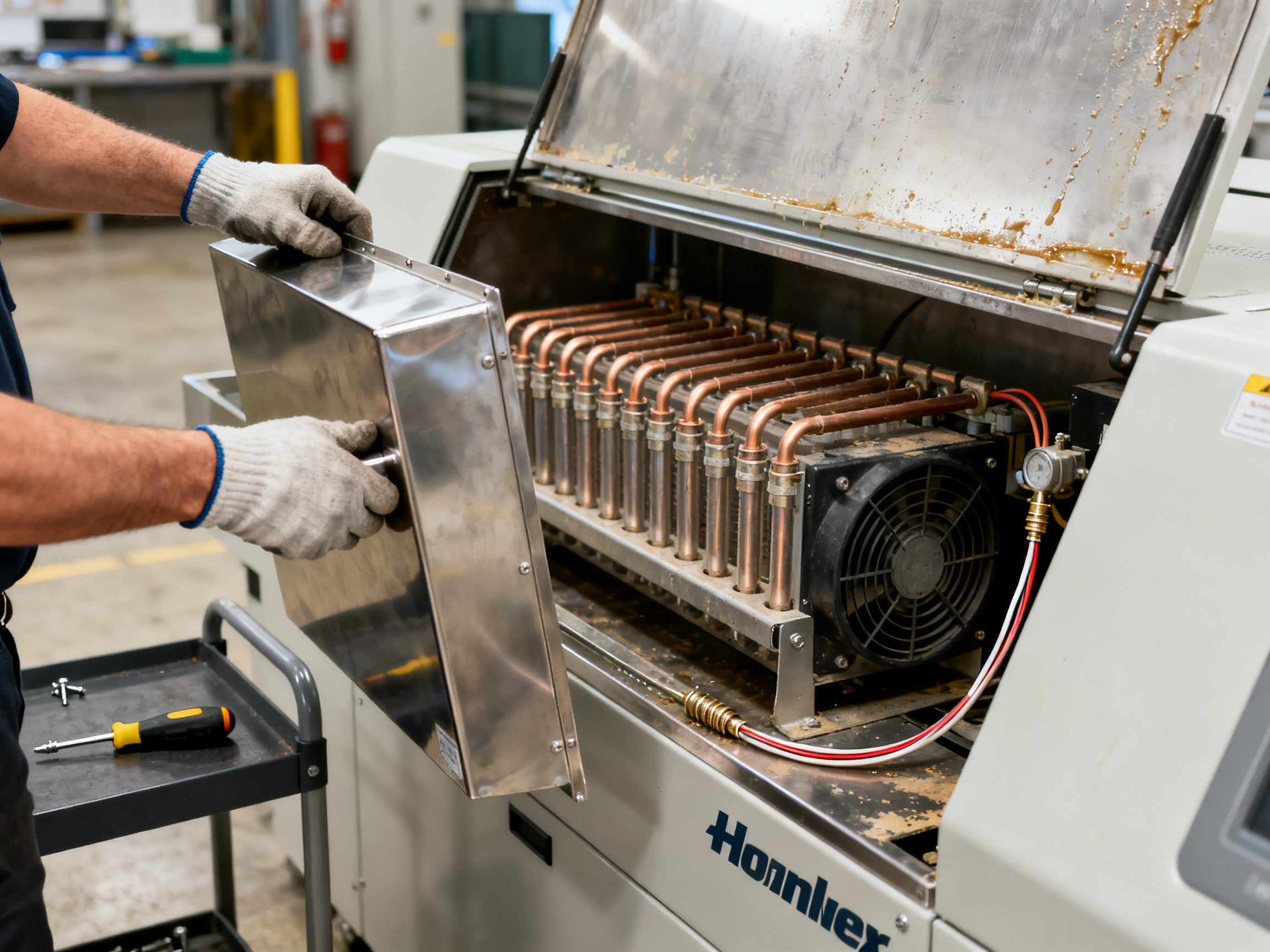
Watch the service clearances too. Technicians need room to pull a plenum, change a heater, and reach the exhaust connection. Manufacturers that build ovens for real factory floors document those clearances in the installation manual, and S&M Co. Ltd. (Shenzhen Chuxin Electronic Equipment Co., Ltd.) specifies them in the lead-free reflow oven documentation so line integrators can plan the footprint before the machine arrives.
One last note on thermal stability: the structure has to hold heat in, but it also has to keep heat away from the parts that cannot take it. Component temperature limits from the package classification in IPC/JEDEC J-STD-020 set the ceiling, and good insulation and sealing are what make the oven actually deliver a repeatable environment underneath that ceiling.
Next up: Section 3 covers heating zones, elements, and thermal uniformity, including how board loading and airflow balance can expose a profile that looked fine during an empty-oven test.## 3. Heating Zones, Elements, and Thermal Uniformity
Now we get to the part that actually decides your yield.
Every heating zone in a modern reflow oven is a small heating module mounted to the chamber, usually as an upper and lower pair. Inside each module you will find a plenum, a bank of electric resistance elements, a blower or blower pair, and at least one thermocouple feeding a PID controller. The controller drives the elements to hold the air in that plenum at a setpoint, the blower pushes that air across the width of the chamber, and the thermocouple closes the loop.
That upper and lower split is not cosmetic. Most boards absorb heat from both sides, and the balance between top and bottom heat decides how flat a large board stays through the profile. Get it wrong and you get warpage, which turns into head-in-pillow on the next pass.
Zone count and heated length are throughput decisions. More zones give you finer control over where in the curve the board spends its time. Longer heated length means slower conveyor speeds for the same profile, which usually means better uniformity. The tradeoff is floor space and energy draw.
| Zone configuration | Heated length | Typical application | Advantages | Tradeoffs |
|—|—|—|—|—|
| 3 to 4 zones | 1.2 to 1.8 m | Prototype and low-volume lines | Low cost, fast setup | Coarse profile control, longer conveyor at speed |
| 6 to 8 zones | 2.4 to 3.6 m | General SMT production | Good soak control, moderate footprint | More elements to maintain |
| 10 zones and up | 4 m or more | Automotive, aerospace, mixed technology | Fine soak and TAL shaping, double-sided capable | Cost, footprint, energy |
Thermal uniformity is where claims get slippery. An oven with a beautiful empty-oven profile can fail on the line, because the empty test tells you almost nothing about a loaded board. Board mass, copper distribution, spacing between parts on the conveyor, and top to bottom airflow all shift the delta-T.
Pro Insight: An empty-oven thermal uniform survey is a screening test, not a qualification. Push a fully loaded carrier of real production boards through it, with realistic spacing, and profile the same board at the center and at the chamber edge. We have seen a zone set that looked within 5 C across the width on an empty run widen past 15 C once a heavy copper-dense board set was running, because the board itself became a heat sink for the bottom zone and a heat source for the top one.
Calibration and sensor placement matter just as much. Controllers that tune themselves on a cold start can overshoot, and thermal mass means recovery after a board load takes time. Good ovens log zone temperatures, flag drift, and support scheduled calibration. Sensor placement should be in the airstream, not sitting against a wall where it reads chamber lag rather than process air.
The most common design measure against localized overheating is airflow that sweeps the full board width rather than pointing at it. That is also where hot air and cold air designs split. Hot air convection ovens use resistance elements and blowers to heat air. Cold air ovens use a heating element upstream, then recirculate the heated air through dedicated ducts at a high flow rate, with no heaters inside the process chamber. Cold air approaches give faster ramp rates and better bottom-side heating on dense boards, which is why they show up on automotive and military lines. Hot air ovens cost less and suit lighter mixed work.
For the profile windows referenced throughout this guide, paste-specific data such as the Indium SAC305 process guidance remains your starting point for ramp, soak, time above liquidus, peak, and cooling.
One more thing that matters for lead-free work: nitrogen. Where oxidation is a problem on fine-pitch or exposed-pad parts, nitrogen atmosphere capability in the reflow oven keeps the joint surface bright and improves wetting margin. It is not a substitute for profile control, but it widens the window you have to work with.
Next up: Section 4 covers airflow systems and the hot air versus cold air debate in detail, including what each design does to ramp rate and bottom-side heating on dense boards.## 4. What the Reflow Oven Hot-Air Valve Does
Here is the part of the oven most people never think about until it fails. Inside the heating modules, behind the plenums, there are valves and dampers. They do not heat anything. They decide where the hot air goes, and how fast it moves.
A reflow oven hot-air valve is an airflow control device. It regulates, blocks, or redirects heated process air inside a zone, the exhaust path, or the recirculation loop. Which job it does depends on how the machine was designed, so do not assume every oven uses the same layout.
Airflow Schematic
Ambient air -> intake filter -> blower -> heater bank -> plenum
           -> [mixing valve / damper] -> nozzle bank -> process chamber
           -> chamber exhaust -> flux filter -> condensate drain
The valve sits between the plenum and the nozzles, or on the return and exhaust side. Either way, it sets flow.
Why Valve Position Matters
Think of the zone as a bucket of hot air. The heater adds heat. The valve decides how much heat leaves through the nozzle side and how much recirculates. Turn the valve more open and you push more air across the board, so the board cools faster in the soak zone but picks up heat faster later. Close it down and flow drops, the board sits in hotter air, and delta-T across the chamber grows.
The chain of cause and effect looks like this:
- Valve opening sets how much air moves through the nozzle bank.
- Blower speed sets how much air the plenum can deliver.
- Plenum pressure tells you whether the nozzle bank is starved or flooded.
- Nozzle flow decides the heat-transfer coefficient at the board surface.
- Zone response time follows from all of it.
A higher heat-transfer coefficient means the board tracks air temperature more closely. A lower one means the board lags behind and keeps its own heat longer.
Valve Types You Will Run Into
| Valve type | How it works | Where you see it | Notes |
|—|—|—|—|
| Proportional damper | Motor moves a blade to a commanded position | Modern multi-zone ovens | Lets the recipe trim airflow per zone |
| On/off valve | Fully open or fully shut | Simpler single-loop ovens | Coarse control, no fine trimming |
| Exhaust damper | Controls how much hot air leaves the chamber | Zones with separate exhaust paths | Affects chamber pressure and heat loss |
| Recirculation damper | Balances fresh air against returned air | Nitrogen-assisted and high-humidity designs | Tends to drift as filters load up |
| Burner damper | Gas burner output control | Older gas-fired or hybrid ovens | Few new builds use this today |
Troubleshooting Table
| Symptom | Possible airflow cause | Quick test | Corrective action |
|—|—|—|—|
| One edge runs 10 °C or more colder | Damper stuck, nozzle bank partially blocked | Compare edge to center profile | Clean nozzles, check actuator stroke, recalibrate zone |
| Zone overshoots on setpoint | Damper near closed, little cooling flow | Watch blower current and plenum pressure | Restore damper range, verify filter is clean |
| Zone never reaches setpoint | Exhaust damper open, heat leaking out | Compare intake and return temperatures | Close or recalibrate exhaust damper |
| Profile changes after a few hours | Filter loading shifts flow | Log zone pressure and profile at shift start and end | Clean or replace filters, add a schedule |
| Bottom side much cooler than top | Downward flow restricted | Hold a hand near the board underside, or run an empty-board profile | Open the underside damper, clear the lower plenum |
One quick tip: If a zone will not settle, check the filters before you touch the recipe. A loaded filter changes flow, and a controller will fight it.
Oven makers such as S&M Co. Ltd. (Shenzhen Chuxin Electronic Equipment Co., Ltd.) build these airflow controls into their lead-free reflow ovens, and the setup manual shows where each damper lives. Ask for that drawing before the machine ships. It saves an afternoon of guessing later.
And remember the rule from earlier in this guide: the zone setpoint is a command, not a promise. The valve decides how well the board obeys it.
Next up: Section 5 covers the airflow system as a whole, including what hot-air versus cold-air designs do to ramp rate and bottom-side heating on dense boards.## 5. Hot Air or Cold Air? Understanding Reflow Heating and Cooling Circuits
Here is something that trips up buyers. They ask about hot air versus cold air ovens as if the two designs compete. They do not. They do sequential jobs on the same board.
Hot recirculated air does the heating. It brings the assembly up through preheat, soak, and reflow. Then the cooling zones take over, pulling heat out of the board with ambient or chilled air so the joint solidifies at a controlled rate. Different circuit, different job, same conveyor ride.
HEATING CIRCUIT                          COOLING CIRCUIT
Heater bank -> plenum -> nozzles         Chilled or ambient air
        |                                     |
        v                                     v
  Process chamber (peak zone)          Cooling fan -> ducted jets
        |                                     |
        v                                     v
  Air mass + radiant heat             Forced convection over board
  lift board to 230-260 C              pulls heat to 25-40 C
| Cooling method | How it works | Best fit | Watch out for |
|—|—|—|—|
| Passive air cool | Ambient air circulates around the board in a cooling zone | Low-volume work, forgiving alloys | Slow ramp down, weak on heavy copper boards |
| Forced convection | Dedicated fans push air across the board top and bottom | Most production SMT lines, better uniformity | Fan failure is a common downtime cause |
| Water-assisted heat exchanger | Cooled water coil conditions the air stream before it reaches the board | Fast throughput, thermal-mass heavy boards, automotive | Cost, water supply, corrosion risk in the loop |
| Controlled cooling with profile capture | Damped airflow, often zone-by-zone ramp control | High-reliability work needing repeatable solidification | Needs a validated recipe and a profiler |
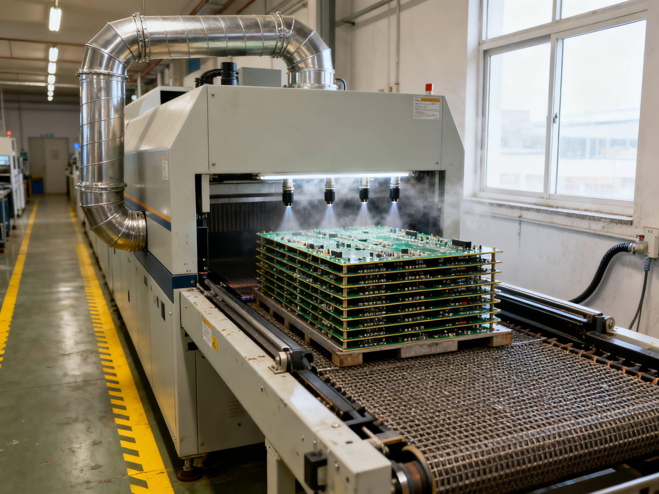
Now the part that matters for quality: the cooling rate.
Too fast and you get thermal shock. The outer skin of a joint can drop below its solidus while the core is still molten, which drives stress into the joint and can microcrack the bond. Too slow and the solder sits in a semi-molten state for too long, which pushes intermetallic growth and dull, grainy joint appearance. Both extremes also invite warpage, because the board is contracting while the joints are still moving.
There is also a downstream handling problem. A board that exits the oven at 90 C instead of 40 C goes into pick-and-place, AOI, or packaging still warm, and a warm board still outgassing flux residue is a board that can pick up contamination and shift components during handling.
The SAC305 process windows quoted earlier in this guide put recommended cooling at 2 to 6 C per second, per the Indium SAC305 paste guidance. That is a paste-specific recommendation, so validate against your own board, your component limits, and your customer’s specification.
Product temperature through the last heating and cooling zones

260 C |          ___-- Peak
      |        _/
220 C |      _/  TAL
      |    _/
150 C |  _/  Soak
      | /
 40 C |/_______________________________
      |                              \___
 25 C |                                  \____  Exit temp
      +--------------------------------------> Time
         Zone 7   Zone 8   Cooling 1  Cooling 2
Bottom line: heating design decides whether the paste melts properly. Cooling design decides whether the joint survives. Ovens from S&M Co. Ltd. (Shenzhen Chuxin Electronic Equipment Co., Ltd.) build the heating and cooling circuits as separate, controllable modules, so the same machine can be tuned for a heavy mixed-technology board or a small sensor assembly instead of running one generic profile for everything.
Next up: Section 6 covers temperature control, thermocouples, PID loops, and how calibration drift shows up as profile drift on the line.## 6. Conveyor, Controls, Exhaust, Nitrogen, and Line Integration
A reflow oven has two personalities. The thermal side decides joint quality. The handling and control side decides whether you ever get to see the thermal side at all. This section covers the reflow oven components that move boards and the systems that watch them while they move.
Conveyor and board handling
Most SMT lines run a mesh belt conveyor because it supports dense boards and odd-shaped assemblies without smearing paste. Edge rail conveyors show up when the work is long and narrow, like LED modules or driver boards, where a full mesh would trap solder debris. Large heavy boards usually need a center support roller so they do not sag onto the belt and pick up solder balls from previous passes.
Speed control runs through a variable frequency drive, commonly covering roughly 100 to 2000 mm per minute. Width adjustment for different board sizes should be possible without tools. Transfer height at the entry and exit has to match the upstream printer and placement machine, and manufacturers usually quote SMEMA or a similar standard. Anti-jam protection matters more than buyers expect: photoeyes that detect board presence, an overload clutch on the belt drive, and a defined stop-and-alarm response when a board hangs up.
Controls, logging, and traceability
The control layer is where a reflow oven becomes a production asset instead of a heated box. A PLC or industrial PC runs the zone PID loops, the conveyor drive, the alarms, and the recipe database.
Thermocouples + fans + heater current + belt speed
                    |
              Analog input
                    v
          PLC / industrial PC
        (PID loops per zone)
     +-----+--------+--------+
     v                v        v
   HMI screen    Recipe store   Data log / MES
  + alarms      + version ctrl  + traceability
Recipe storage should hold the full program, not just zone setpoints, and each saved recipe needs a version number and a lock. Data logging normally captures zone temperatures, belt speed, run time, and alarms per board run. That log is what lets you answer a customer question about a lot that shipped three months ago.
Traceability usually runs on serial or barcode data attached to the board at the printer, carried through placement, and confirmed at the oven exit. Equipment from S&M Co. Ltd. (Shenzhen Chuxin Electronic Equipment Co., Ltd.) is built to sit inside an industrial SMT production line like this, with standard line protocols rather than a closed proprietary island.
Exhaust, nitrogen, power, and interlocks
Flux exhaust pulls acidic vapor out of the chamber through stainless ducting and filtration, with a condensate drain at the low point. Filters load up, so the exhaust fan speed or chamber pressure is worth watching as a health indicator. Oxygen monitoring matters mainly when nitrogen is used for oxidation control.
Nitrogen management covers the gas supply, flow metering, and the purge sequence at startup and shutdown. Nitrogen widens your wetting margin on fine-pitch and exposed-pad parts, but it does not replace profile control.
Standby modes let the oven idle at reduced temperature to save energy without a full cold start, and power management on modern machines tracks element current and flags drifting heaters.
Machine safety interlocks include door and hood interlocks, fan rotation proof, gas leak detection on heated gas ovens, and emergency stops that cut power to heaters while keeping controls alive.
Feature priorities by industry
| Priority | Consumer electronics | Automotive | Aerospace and military |
|—|—|—|—|
| Throughput | Highest | Medium | Low |
| Traceability and logs | Basic | Lot level with revision control | Full serial traceability |
| Nitrogen | Optional | Common | Where specified |
| Profile validation | Per board family | Narrow validated windows, SPC | Documented qualification per product |
| Cooling | Forced convection | Water-assisted for heavy boards | Controlled cooling with captured profiles |
Expert Tip: Before you accept an oven, watch it run a full production board, not a bare laminate coupon. The controls will look perfect on the coupon, and the conveyor may sag a heavy board or drift in width on the first loaded cycle.
Next up: Section 7 covers factory assembly through commissioning, including FAT, SAT, ramp-up, and calibration steps that turn a delivered machine into a qualified line asset.## 7. How SMT Heating Equipment Is Made: Factory Assembly to Commissioning
The oven you sign for on the delivery sheet is a machine long before it is a product. It gets built in a defined order, and most of the problems that show up in year two were decided on the factory floor, not in your process window. Here is the sequence.
Process spec -> thermal + airflow simulation -> frame fabrication
   -> chamber, insulation, sealing -> heaters, blowers, plenums
   -> wiring + controls integration -> software and recipe config
   -> in-house checkpoints -> FAT -> ship -> site install
   -> SAT -> operator training -> recipe qualification -> handover
Engineering starts with your process, not the machine. The design team defines the profile envelope (ramp, soak, time above liquidus, peak, cooling), the throughput target, and the board family it must handle. That feeds a thermal and airflow model of the chamber, where the simulation decides plenum geometry, nozzle spacing, element placement, and blower sizing. Getting this wrong on paper is how you end up with a 15 C edge-to-center delta on a loaded carrier.
Frame fabrication follows: steel cut, welded or bolted into modules, machined flat so the chamber seats properly, then powder coated. Next comes the stainless chamber, its plenums, the insulation blankets, and the seals. Heaters, blowers, and dampers get mounted after that, because bolting fragile elements into a frame that is still being handled is a good way to crack a heater.
Wiring and controls come last on the build floor: zone thermocouples routed as shielded twisted pairs, PLC and HMI, fan drives, alarms, grounding. Software configuration then sets the PID loops, the recipe library, and the logging paths.
CHECKPOINT                  WHAT IT PROVES
Insulation inspection       No hot spots on chamber walls or door frames
Electrical safety test      Insulation resistance, grounding, interlocks
Airflow balance             Every zone holds setpoint at equal flow
Thermocouple calibration    Sensor reads true at every zone temperature
Conveyor alignment          Belt tracks straight, no drag, correct height
Leak and exhaust check       No process air escaping, condensate drains
Burn-in                     Elements, fans, and dampers survive 24 h loaded
Loaded board trial          Profile holds with real mass on the belt
Then there are the two tests everybody talks about, and they do different jobs.
| Test | Where it happens | What it covers | Sign-off means |
|—|—|—|—|
| FAT | Factory, before shipping | Build quality, calibration, safety, empty and loaded run, documentation | Machine is ready to ship |
| SAT | Your plant, after install | Power, exhaust hookup, line interlocks, conveyor height, actual profile | Machine is ready to produce |
A FAT that only proves the oven heats is not worth much. The useful FAT runs a populated board through a full profile and hands you the recorded data.
After SAT comes handover, and this is where projects often get sloppy. You should get operator training on recipe loading and alarms, a documented spare-parts list with recommended stock, the damper and heater layout drawing, calibration certificates, and the full maintenance schedule. Then recipe qualification runs on your own boards. Use the paste maker’s process window as your starting point, such as the ramp, soak, time above liquidus, peak, and cooling guidance in the Indium SAC305 process data, then validate against your components, board construction, and customer limits. The narrowest limit governs.
One final note from the commissioning side. The oven you qualify is not the oven you keep. Filters load, dampers drift, elements age. Build a routine re-verification schedule into your preventive maintenance plan now, so the profile you validated in October is still the profile you have in March. Lead-free reflow oven builders such as S&M Co. Ltd. (Shenzhen Chuxin Electronic Equipment Co., Ltd.) ship this handover set with the machine, which is worth asking to see before you release the purchase order.
Next up: the conclusion ties oven construction back to the process you need to control, with a checklist for evaluating a reflow oven before you buy it.## 8. Design Choices That Reduce BGA, QFN, and High-Density Assembly Defects
Here is the part that keeps production engineers up at night. A board comes out of the oven looking perfect, the AOI gives it a green light, and the X-ray tells a different story. Voiding at 30 percent under a large BGA. Head-in-pillow on a QFN. A row of solder balls nobody can explain.
None of those defects announced themselves. They were built into the process, quietly, hours earlier.
Good reflow oven construction attacks them directly. But first, the harder question: is the oven even the culprit?
| Defect | Oven-side cause to rule out | More likely non-oven cause | First check |
|—|—|—|—|
| Voiding under BGA | Uneven top/bottom heat, long soak with poor outgassing | Stencil aperture volume, paste volume under the lid | X-ray plus a solder volume calculation |
| Head-in-pillow | Warpage support, uneven heating, excessive soak | Component coplanarity, pick-and-place placement error | Board flatness during profile |
| Tombstoning | Thermal shock from a fast ramp on a small package | Solder paste slump, paste print slump | Ramp rate and print condition |
| Solder balls | Spatter from fast heating or flux outgassing | Poor stencil release, particles in the line | Ramp rate plus area cleanliness |
| Non-wet open | Oxidation from poor nitrogen coverage | PCB finish chemistry, pad contamination | Joint surface appearance under magnification |
| Component shift | Uneven heating, aggressive cooling | Placement offset, no tack step | Handler alignment and pad adhesion |
The pattern matters. If the defect rate tracks board type, the oven is only part of the story. If it tracks position on the board, or edge versus center, or the first board after a changeover, look at the oven. Those signals come from airflow, zone balance, and heat mass, and they are the ones the oven’s own sensors cannot see.
Pro Tip: Change one variable at a time. Run the same board, same paste, same print, and shift only conveyor speed by 10 percent. If the defect rate moves, you have a thermal cause. If nothing moves, stop blaming the oven and go check the stencil.
A troubleshooting sequence that actually works:
- Profile the board with thermocouples at the BGA corner, center, and a shadowed location. Coldest and hottest point tell you more than peak does.
- Check zone response and airflow balance on a loaded carrier, not an empty run. A set that looked even at 5 C delta can widen past 15 C with real copper on the belt.
- Cross-check with AOI for surface symptoms and X-ray for internal ones. Then reconcile the two against the profile.
- Run one controlled experiment. If time above liquidus is out of the recommended 45 to 60 second window for SAC305 per the Indium RMA-155 paste data, fix that before touching anything else.
- Check component moisture handling. Package classification under IPC/JEDEC J-STD-020 governs how many reflow cycles a part survives, and a baked-part discipline violation looks exactly like a thermal defect.
Ovens built for high-density work, such as the lead-free reflow systems from S&M Co. Ltd. (Shenzhen Chuxin Electronic Equipment Co., Ltd.), pair multi-zone airflow control with nitrogen capability and profile logging, so the process window can actually be held rather than assumed. Build those controls into your line and defect reduction stops being a guessing game. It becomes a chart you can read.
Next up: the conclusion ties oven construction back to the process you need to control, with a checklist for evaluating a reflow oven before you buy it.## 9. How to Evaluate a Reflow Oven for a High-Volume SMT Line
Buying a reflow oven is one of the last big capital decisions on an SMT line, and it is usually made by someone who has never watched one run a loaded carrier. So let’s make the process less guessy.
Start with your own numbers, not the brochure. Write down board length and width range, heaviest board mass, product mix per shift, target throughput in boards per hour, solder alloy, whether you need nitrogen, how complex your profiles have to be, available power and exhaust, floor footprint, and which line protocols your printer and placement machines speak. Everything else in the comparison depends on this list.
The procurement checklist
REQUIREMENT              WHY IT MATTERS                          ASK FOR
Board size and mass      Conveyor width, sag, support roller    Loaded board trial
Product mix per shift    Zone count needed for soak shaping     Profile simulation
Throughput (boards/hour) Heated length and conveyor speed       Cycle time test
Solder alloy             Peak temperature ceiling                Recipe library
Nitrogen required?       Wetting margin on fine pitch           O2 monitoring data
Profile complexity       Soak zones, TAL control, cooling       Ramp/TAL data
Utilities                Power draw, exhaust, cooling water     Site prep drawing
Floor space              Service clearance and footprint        Layout drawing
Line integration         SMEMA, handshake, MES data              I/O list and protocol
Capital cost is the smallest number on the sheet
The purchase price usually looks like the biggest line item. It is not. Over a five-year life, energy, nitrogen, maintenance labor, spare parts, and changeover time usually cost more than the machine.
TCO over 5 years = Purchase price
                 + (kW x duty hours x rate x 5 years)
                 + Nitrogen consumption
                 + Service labor hours x technician rate
                 + Spare parts and consumables
                 + Downtime cost x annual downtime hours
                 - Yield gain value
The assumptions matter more than the formula. Duty hours should reflect real shift patterns, not nameplate capacity. Downtime should use your own MTBF history if you have it, and vendor-published figures if you do not. And the yield line is the one most buyers leave at zero, which quietly makes every oven look the same.
| Cost driver | What drives it | Question to ask |
|—|—|—|
| Energy | Heater kW, insulation quality, standby mode | What is kW at full load and at standby? |
| Nitrogen | Flow rate per zone, purge cycles | What is consumption per hour of run time? |
| Maintenance | Element life, fan life, filter interval | What is the documented service schedule? |
| Spare parts | Price and lead time for heaters, TCs, belts | List price and delivery lead time |
| Downtime | Failure modes, remote support, spares stock | What is the worst-case response time? |
| Changeover | Recipe load, width adjust, calibration | How long from one board family to the next? |
What to demand before you sign
Ask for sample-board profiling with data, not a video. A profile on a bare coupon tells you the oven works; a profile on one of your boards tells you it works for you.
Also ask for the acceptance criteria in writing. Which documents arrive on delivery? What is the factory acceptance test scope, and what is the site acceptance test scope? Who witnesses each one?
Then ask for reference installations you can actually visit, and check whether the supplier has delivered a line with more zones than yours, or a second oven into an existing plant. Scalability evidence beats a roadmap slide.
Finally, get service-level commitments on paper. Response time, spare parts stocking, and whether a technician can reach you on a Sunday when a cooling fan dies. On a high-volume line, an hour of downtime is not an hour. It is a shift.
From Our Experience: Never accept an oven on an empty-chamber profile. Run your own representative production boards through it during FAT, profile the coldest and hottest points, and only sign once the recorded numbers sit inside your own limits. An oven that passed in the factory with a clean laminate can behave very differently with your boards loaded.
Equipment built for this kind of line work, such as the lead-free reflow ovens and full SMT production lines from S&M Co. Ltd. (Shenzhen Chuxin Electronic Equipment Co., Ltd.), is usually specified around the same questions: cycle time on a given board family, thermal profile data on customer boards, and documentation at handover. Ask for all three in the quotation, not after the purchase order.
The narrowest limit still governs. Whatever the paste maker recommends for ramp, soak, time above liquidus, peak, and cooling, such as the SAC305 windows in the Indium RMA-155 paste data, gets checked against your component package classification, your board materials, and your customer’s specification. The oven is the tool that delivers the curve. Your board decides what the curve must be.
Conclusion: Match Oven Construction to the Process You Need to Control
The takeaway is simple. A reflow oven is a system, not a heater count. Mechanical stability, controlled heating, balanced airflow, cooling, conveying, software, safety interlocks, and validation all have to line up, or the thermal curve you paid for never reaches the solder joint.
Five things to take with you:
- Setpoint is not temperature. What the controller commands and what the component actually sees are two different numbers. Profile your own boards.
- Uniformity is a loaded-board property. An empty-chamber survey screens the oven; only a full carrier of real production boards qualifies it.
- Cooling designs the joint. Heating decides if the paste melts, cooling decides if the joint survives.
- The narrowest limit governs. Paste window, package classification, board materials, and customer spec all apply, and the tightest one wins.
- Buy for the lifetime. Energy, service, spares, and downtime usually cost more than the purchase price over five years.
Pro Tip: Before you request a quotation, write down board size and mass, throughput, alloy, nitrogen need, utility limits, footprint, and line protocols. A vendor who quotes from your numbers instead of their brochure list is already doing the right thing.
Ready when you are: send your board family and volume requirements to S&M Co. Ltd. (Shenzhen Chuxin Electronic Equipment Co., Ltd.) and ask for a technical proposal that includes profile data on a customer board, cycle time figures, and a documented handover package. And re-verify the recipe quarterly; filters load, dampers drift, elements age.
The profile windows used throughout this guide, such as the SAC305 ramp, soak, time above liquidus, peak, and cooling ranges in the Indium RMA-155 paste data, are your starting point. Your board decides what the curve has to be.