
Published: 02 November 2026
Last Updated: 02 November 2026
Reading Time: 17 minutes
This guide is based on a roughly 4,150-word technical reference covering SMT production line layout, equipment selection, PCB loading and unloading, and defect reduction for BGA, QFN, and high-density assemblies. No reviewer credit is listed, since no named reviewer with documented credentials has been supplied for this article.Boards are getting denser. Components are getting smaller. And the solder has to work without lead.
That is the pressure most factories feel right now, and it is why picking an SMT machine on spec sheet alone can sink a project. An SMT machine is one station in a connected system. What actually determines your output is how the line flows, how material moves between stations, and how the process is balanced end to end.
Here is the flow in its simplest form:
Loader → Printer → SPI → Mounter → Mounter → Reflow Oven → AOI → Unloader
Eight stations, and every transfer between them is a place where boards can wait, jam, or arrive out of sequence. That is what this guide breaks down.
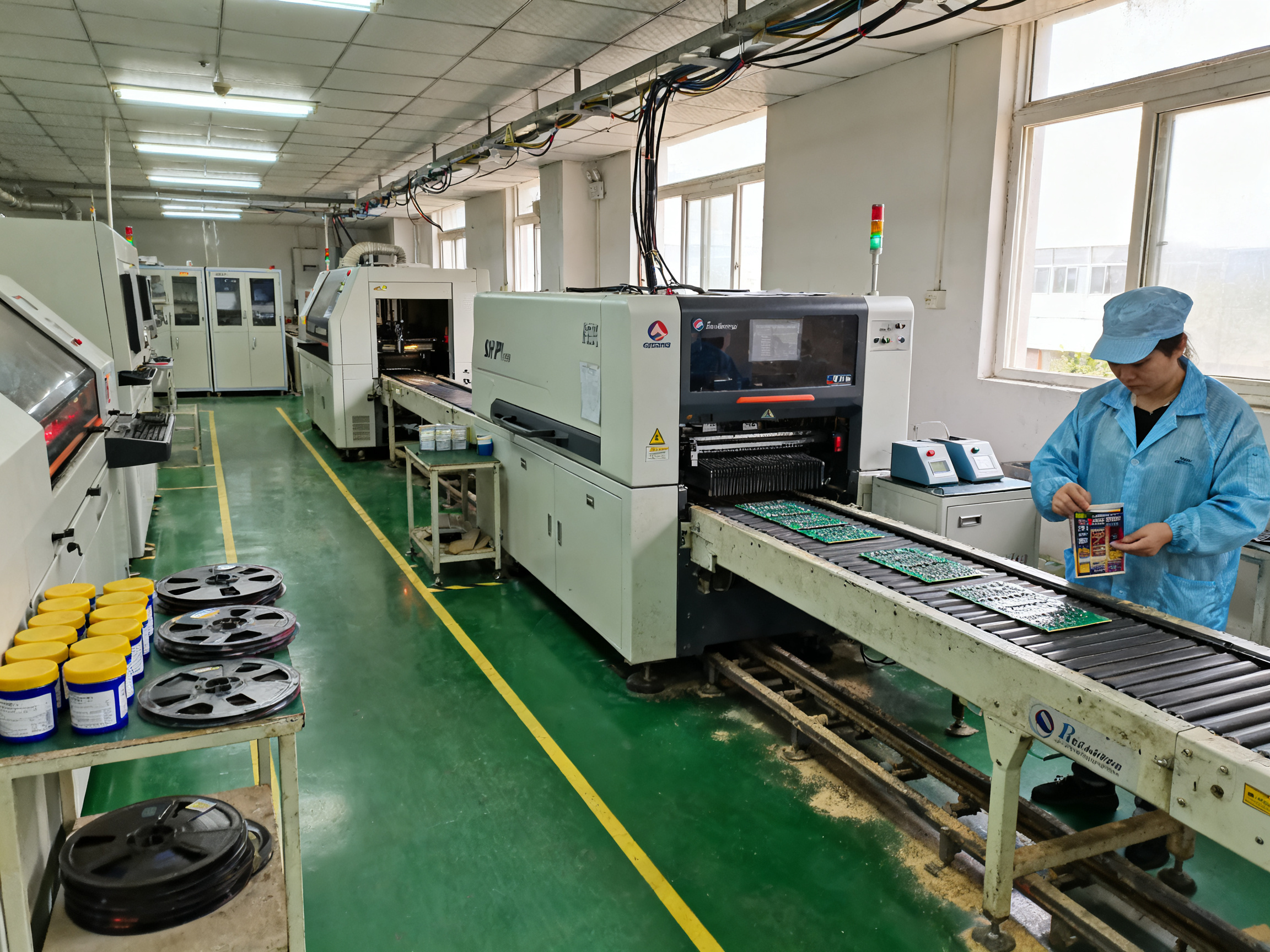
What this guide covers
- Layout: how to plan an SMT production line layout so product moves in one direction without piles of buffers
- Equipment: the core SMT production line equipment list, machine by machine, including what a small SMT production line actually needs
- Transfer: PCB loading and unloading, buffering, and how machines hand boards to each other
- Quality: reducing defects on BGA, QFN, and high-density assemblies
- Buying: what to check before you purchase, and how to match the line to your growth plan
First, understand the process
Equipment selection starts with the process, not the price list. If you know what is on your boards, you can pick machines that can handle them.
Two questions to answer first:
- What does SMT mean in production? Surface mount technology means components sit directly on the board surface and are soldered in a single reflow pass. That is different from through-hole, where pins go through drilled holes.
- What standards apply? IPC J-STD-001J governs the soldering process itself, and it is meant to be used alongside IPC-A-610 for finished-assembly acceptability. Neither one, on its own, tells you how many boards to inspect or which reflow profile to run.
Get those two answers straight, and the rest of the guide gets a lot easier.
Next: how to plan the layout properly.### About the Author
This article was prepared by the S&M Co. Ltd. (Shenzhen Chuxin Electronic Equipment Co., Ltd.) editorial team, with technical input from its SMT equipment engineering group, which supports lead-free reflow ovens, wave soldering machines, and complete SMT production lines for consumer electronics, semiconductor, and military assembly work.
Editorial note: No named author with verifiable credentials was supplied for this guide at the time of publication, so we have left the reviewer and author fields open rather than attach unverified titles to the article. Before this piece goes live, the publication team should replace this box with the line planner or process engineer’s name, role, certifications, and years of hands-on SMT line experience, then link to a full author profile if one exists.
Want to talk through your line setup, from printer placement through reflow and AOI? S&M Co. Ltd. builds equipment and full SMT production line setups for factories that need lead-free manufacturing with tighter defect control. Talk with our team about your product mix, volume, and inspection requirements.## 1. What Is an SMT Production Line and How Does SMT Work?
So here is the question every line planner asks first: what is SMT production line, really? Strip away the vendor brochures and you get something simple. An SMT production line is a connected set of machines that takes bare printed circuit boards and builds electronic assemblies on them, in one direction, without anyone soldering by hand.
Surface mount technology is the core idea. Instead of pushing component pins through holes in the board, the parts sit flat on pads on the board surface and are held in place by solder paste until a reflow oven melts everything into a solid joint. That is what is smt in manufacturing, in about thirty seconds.
Now, the SMT production line meaning that most people actually want is shorter than the textbook version. It is a flow of work where each station hands the board to the next. And each SMT machine in that flow has one job, done well.
The process, station by station
Here is how SMT works in practice, in the order a board sees it:
Loader → Solder Paste Printer → SPI → Mounter → Mounter → Reflow Oven → AOI → Unloader
Board loading. A loader takes bare PCBs from a magazine or tray and places them onto a conveyor or direct-transfer shuttle at a controlled pitch. From here on, the board is on a carrier or travels directly from machine to machine.
Solder paste printing. A stencil sits under the printer head. A squeegee pushes solder paste across the stencil, and apertures cut into the stencil deposit a controlled amount of paste onto each pad. No paste means no joint, so this station sets the ceiling on quality for everything downstream.
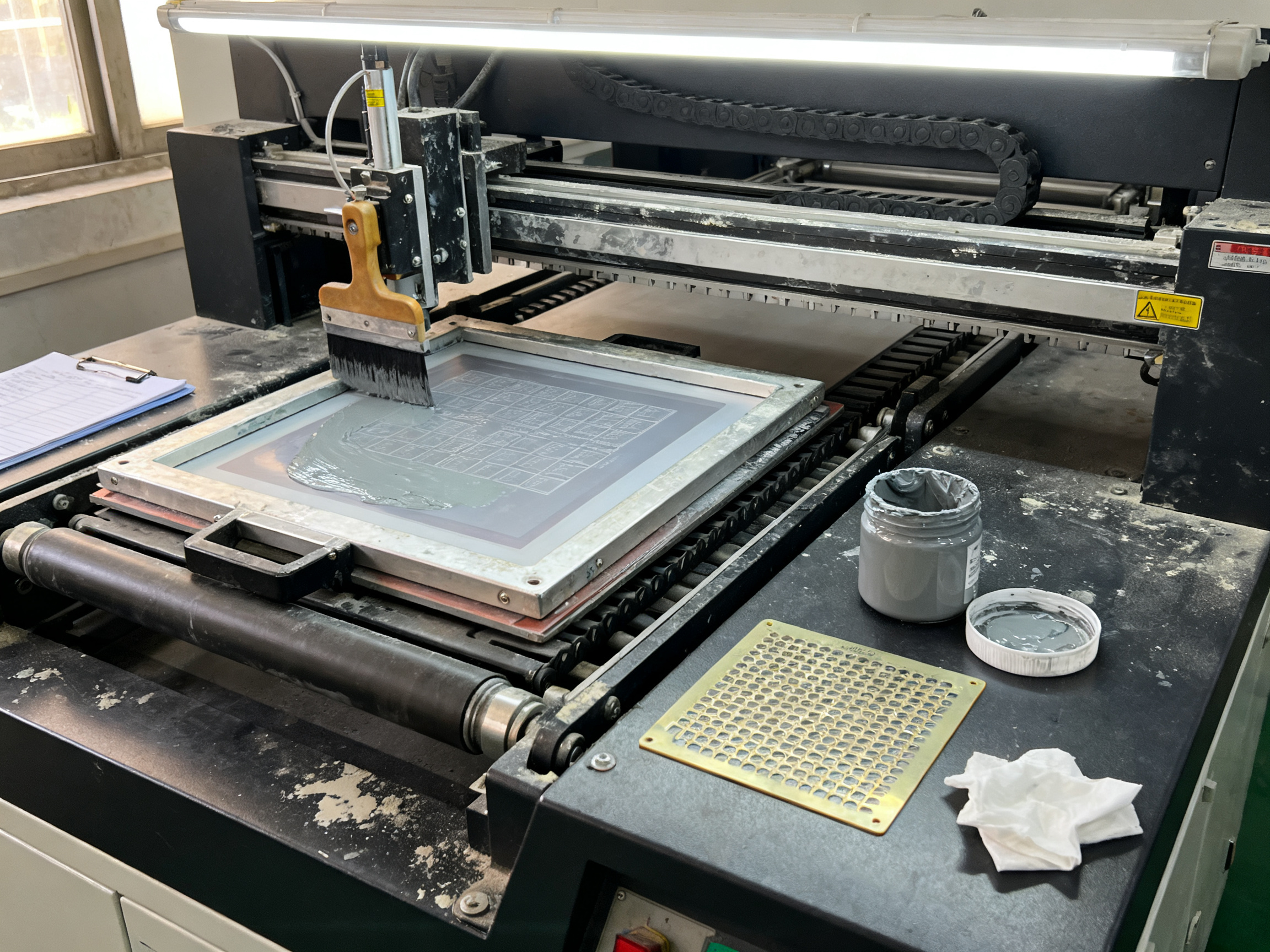
SPI, solder paste inspection. A 3D camera checks the deposited paste right after printing, before any component is placed. It catches too little paste, too much paste, shifted paste, and paste sitting on the wrong pad. Fixing a defect here takes seconds. Fixing the same defect after reflow takes a rework loop, or worse, a scrap.
Component placement. The mounter (pick and place machine) picks components from feeders and places them onto the pasted pads. Small parts land on paste-printed pads, and larger parts are picked from tape and reel or trays and set onto the board with enough paste to form a reliable joint. Most lines run two mounters in sequence, split by component family, so the fine-pitch machine is not slowing down while a bulky connector waits.
Reflow soldering. The board moves through a reflow oven on a conveyor or pallet. The oven follows a controlled thermal profile: ramp, soak, and peak, so the solder alloy melts, wets the component terminals and the pad, and forms a metallurgical joint. After 2026 lead-free rules, most factories run SAC305 or SAC305 plus additions, which melts around 217 to 220°C and demands a tighter profile than the old leaded processes.
Post-reflow inspection (AOI). An automated optical inspector looks at the finished assembly and checks for defects you cannot see any other way: missing components, tombstoning, insufficient solder, solder bridges, skew, and opens. For hidden joints under BGA, QFN, and LGA packages, AOI sees very little, so X-ray inspection takes over.
Unloading. The unloader takes finished boards off the line, usually into a tray or a stacker, and sends them to the next process: testing, coating, or packing.
SMT versus through-hole
This matters more than most buyers expect, because it changes the whole machine list.
| Factor | SMT assembly line | Through-hole assembly |
|—|—|—|
| Component mounting | Directly on the board surface | Pins through drilled holes |
| Board area needed | Less space per part | More space per part |
| Component density | High, supports fine pitch and area arrays | Low, larger part spacing |
| Mechanical strength | Weaker, needs careful handling | Stronger joints |
| Typical process | Print, place, reflow | Insert, wave or selective solder |
| Best fit | Smartphones, semis, automotive ECU, military boards | Connectors, big capacitors, transformers, legacy boards |
| Inspection method | AOI plus X-ray for hidden joints | Visual and dimensional checks |
| Labor profile | Automated, high setup accuracy | More manual insertion work |
The neat part is that most real factories are not pure one or the other. They are mixed.
When you need both technologies
Three hybrid approaches are common in 2026 production:
Wave soldering. The board is loaded face down onto the bottom of a wave of molten solder, usually in a carrier pallet. It works well when a board has many through-hole joints and a relatively open underside. It struggles with shadowing, bridging, and skips, and it can cook parts that were already placed.
Selective soldering. A nozzle or multi-head system solders only the specific joints that need it, usually a handful of through-hole parts on an otherwise dense SMT board. This is the usual answer when a full wave would be unsafe. It needs nozzle clearance planning, its own profiling, and flux and cleaning steps before conformal coating.
Pin-in-paste. Pins are inserted into plated holes that already hold paste, then reflowed in the same pass as the SMT components. It removes a whole solder step, but only works when the aperture design, hole fill volume, and pin geometry all line up.
The general rule: SMT placement and reflow come first. Through-hole soldering comes after. Doing it the other way around risks knocking freshly placed components loose.
One more thing worth saying plainly. IPC J-STD-001J sets how the soldering process is controlled, and IPC-A-610 sets whether the finished assembly is acceptable. Neither standard tells you how many boards to inspect, how fast to run the line, or which reflow profile to use. Those decisions come from your product class, your customer spec, and your actual process data. Treat any vendor who quotes a single fixed profile as selling something you will have to qualify yourself.
Next up: how to plan the SMT production line layout so boards actually move through these stations without piling up.
3. The Equipment: What an SMT Line Actually Needs
Once the layout is decided, choose equipment by its function in the process rather than by the largest specification on the datasheet. A practical SMT production line normally includes the following systems:
- Loader and unloader. These automate board handling and help keep cycle time consistent. For low-volume or mixed production, manual loading may be more economical, provided operators can work safely and repeatably.
- Stencil printer. The printer deposits solder paste accurately and consistently. Pay attention to stencil size, paste inspection features, cleaning cycles, and support for the board formats you actually run.
- SPI. Solder paste inspection catches insufficient, excessive, or misaligned paste before the board reaches the mounter. This is especially important for fine-pitch components and high-reliability assemblies.
- Component mounter. Placement speed matters, but feeder capacity, component range, software, and changeover time usually determine real output more than headline placement speed.
- Reflow oven. Select an oven for the board size, thermal profile, available power, and required process control. Nitrogen systems can help with certain fine-pitch or sensitive applications, but they add cost and maintenance requirements.
- AOI. Automated optical inspection checks component presence, position, polarity, and solder appearance after reflow. It does not replace process control, so establish clear defect-escalation procedures.
- Conveyors and buffering. Use the conveyor system to maintain controlled spacing and provide the buffer capacity needed to isolate brief upstream or downstream stoppages.
- Traceability and data systems. At minimum, record the board revision, paste stencil, feeder setup, placement program, reflow profile, inspection results, and operator actions for each production lot.
Match the line to the product
A small SMT line can be highly productive when it is dedicated to one board family. A flexible line becomes more useful when several products share compatible feeders, package sizes, and process requirements. Before buying equipment, list the components and board variants that the line must support, then separate the truly common platform from the exceptions.
It is often cheaper to standardize the core process than to buy a machine for every possible job. Keep the printer, oven, inspection method, and conveyor interface consistent where possible. Put specialist equipment in a separate cell or use a manual process for low-frequency work instead of forcing every requirement into the main line.
Compare machines using total effective capacity
Compare SMT line machines with a simple formula:
Effective output = nominal capacity × availability × yield × utilization
For example, a machine rated at 100 placements per minute may achieve only 70 effective placements per minute after accounting for setup, feeder changes, verification, stops, and defects. Compare machines using the same board and the same operating assumptions. A slower machine with faster changeover and better feeder support can be the better choice for a mixed-product line.
Run a trial build before making a final purchase. Measure paste deposition, placement accuracy, reflow profile stability, inspection coverage, and the time required to change to the next product. The trial will reveal whether the machine matches the layout and the process—not merely whether it meets its published specification.
Expert Tip: Keep a documented golden board and a process-control plan for every active product. A repeatable setup reduces dependence on individual operators and makes it easier to identify whether a future problem comes from the equipment, the material, or the procedure.
The next decision: capacity and automation
The right level of automation is the least complex one that meets your delivery and quality requirements. A manual loader, a semiautomatic inspection station, and a well-designed conveyor may outperform an expensive automated line when volume is low and product mix is high. As volume grows, automate handling and material replenishment first, because those activities often consume the most operator time and create the most bottlenecks.
Finally, design the line so that it can be maintained without dismantling the entire process. Leave access for feeder changes, stencil cleaning, oven maintenance, and board retrieval, and provide clear paths for operators and service technicians. Good equipment in a poor layout still produces poor output; good layout with unsuitable equipment will simply fail sooner.
In the next section, we will examine the small SMT production line in more detail, including how to determine which machines are essential and where a minimal, cost-effective configuration makes sense.## 3. SMT Production Line Equipment: Machine-by-Machine Guide
Buying an SMT machine by the biggest number on the brochure is the most common mistake I see. Placement speed gets all the attention, but it is rarely the constraint that decides your output. Feeder capacity, changeover time, and how a machine behaves when the board is not a perfect rectangle tend to matter more.
Here is the station-by-station view, in line order, with what each machine actually does and the failure it is there to prevent.
| Machine | Purpose and line position | Key specs to check | Quality risk it controls | Question to ask before buying |
|—|—|—|—|—|
| Loader | Feeds bare PCBs from magazine or tray at controlled pitch, first station | Board size range, pitch accuracy, sensor type, tray or magazine support | Skewed insertion, board damage, wrong revision loaded | Does it read a barcode and lock out a mismatched board revision? |
| Conveyor / transfer system | Carries boards between every station | Board width, side-transfer or direct transfer, buffer capacity, edge clearance | Board collision, edge marking, transport damage | How much buffer sits at each machine, and can one station stop without starving the rest? |
| Stencil printer | Deposits solder paste through a stencil onto pads | Stencil size, squeegee type, paste pressure and speed control, cleaning cycle, 2D/3D alignment | Missing paste, too much paste, misaligned print | How many board variants can it print without a manual stencil change, and does it log deposit data per board? |
| SPI | Inspects wet paste before placement | Scan speed, resolution, defect library, inline vs offline mode | Insufficient, excessive, or shifted paste | Can it feed rejects back in, and does it auto-adjust the printer or just alarm? |
| Pick and place mounter | Places components from feeders onto pasted pads | Placement accuracy, feeder capacity and types, component range, software, changeover time, board size | Missing or skewed parts, tombstoning, wrong polarity | How long is a changeover from one product to the next, and how many feeders does that need? |
| Reflow oven | Melts paste and forms the metallurgical joint | Zone count, heating and cooling capacity, uniformity, profile control, board and pallet loading | Insufficient solder, bridges, head-in-pillow, thermal damage | Does the oven log and store a profile per board type, and can it verify uniformity across the work zone? |
| AOI | Inspects the finished assembly optically | Resolution, coverage, false-call rate, defect library, reject handling | Missing parts, polarity, insufficient solder, bridging | What is the measured false-call rate on your actual boards, not a demo board? |
| Unloader | Removes finished boards to tray or stacker | Tray handling, board separation, signal hand-off to test | Mixed revisions in a tray, handling damage | Can it label and route by board type automatically? |
| Traceability system | Connects every station to a lot record | Data capture scope, MES or data collection interface | Untraceable rework, wrong profile on a mixed lot | Can it pull the exact paste, program, profile, and inspection history for one board in one click? |
That last row is where a lot of factories fall short. Standards set the floor for the soldering process and for finished-assembly acceptability, but they do not define your inspection percentages or your process windows. The IPC J-STD-001J contents outline makes that separation clear, and building your own traceability layer around it is what turns compliance into control.
The machines that are optional, and the ones you will end up buying anyway
Board cleaners, depanelizers, conformal coating stations, and X-ray inspection are not part of the core flow. They sit before, after, or beside the line. You will probably still want them.
- Board cleaner. Solderability and paste printing both suffer from contamination, and IPC J-STD-002 and J-STD-003 cover solderability testing. If your boards come from an outside fab, cleaning is cheap insurance.
- Vacuum handling. Fragile parts such as large BGAs and bottom-terminated QFNs need controlled handling to survive transfer.
- Reject conveyor. Failing boards need somewhere to go, otherwise operators stack them on a bench and the traceability story falls apart.
- Depanelizer. V-score or routing breaks boards apart after reflow, and it belongs near the unloader.
- X-ray inspection. AOI cannot see under a BGA or LGA package, so hidden joints need X-ray. Note that IPC-A-610 does not itself set X-ray acceptance criteria, so you define those from your design rules.
- Wave and selective soldering. These extend the line for mixed-technology work, and selective soldering is usually the right choice when only a few through-hole joints remain on a dense board.
Matching specs to your product and volume
Now connect the numbers to reality. A high-speed mounter does you no good if its feeder set cannot hold your component mix, and a reflow oven with plenty of zones still fails if the board is too wide for the conveyor or the ramp is too aggressive for a heavy panel. High-density boards with 01005 passives narrow the process window so much that placement accuracy, paste volume control, and inspection resolution all have to move up together.
Pro Insight: Quoted placement speed is a laboratory number with one board type, one feeder set, and no interruptions. Real throughput drops after feeder changes, program verification, nozzle checks, inspection stops, and material replenishment. When we compare machines for a customer, we quote placements per hour across the actual product mix, because that is the number the customer pays for.
Expert Tip: Before finalizing any placement or reflow purchase, write down your top three throughput killers from the last quarter. Placement speed will not fix a feeder shortage or an unstable paste viscosity problem, so buy against the bottleneck you actually have.
One last practical point. Design the line so it can be serviced without dismantling the process. Leave access for feeder changes, stencil cleaning, oven maintenance, and board retrieval, and keep clear paths for operators and service technicians. Good equipment in a poor layout still produces poor output, and good layout with unsuitable equipment will fail sooner.## 4. PCB Loading, Transfer, Buffering, and Unloading
Every defect that shows up later and gets blamed on the mounter usually started at the loader. Boards enter the line already at an angle, sit crooked in a carrier, or arrive at the printer with a damaged edge. By the time you see the symptom, the cause is three stations back.
So let’s start at the front door.
Loading: where boards enter the line
Most factories run one of three loading approaches:
- Magazine loader. Boards arrive in a stack of magazine frames and are pushed onto the conveyor or shuttle one at a time. It handles heavy board sizes well and keeps the operator’s hands away from the process. Watch the stack size limit, because tall magazines can shake and cause insertion errors.
- Bare board loader. Boards come in trays, cassettes, or single-piece handling. This is the common choice for small batches and mixed products, where a magazine loader would spend more time being refilled than running.
- Vacuum handling. Fragile or bottom-terminated parts need controlled support, and vacuum or soft-grip handling reduces edge marking on coated or polished boards.
Whatever you use, the loader should read a barcode, confirm the board revision, and refuse to run a mismatched part. Board revision mixups are silent and expensive, and a barcode check at the door is the cheapest insurance in the whole line.
Transfer and buffering: the handshake between machines
This is the part most layouts get wrong. A conveyor is not a pipe. It is a set of boards in motion, each one a separate object that can skew, jam, or arrive out of sequence.
┌────────┐   up/down signals   ┌──────────┐   stop gate   ┌─────────┐
│ LOADER │ ───────────────────▶ │ PRINTER  │ ───────────▶ │  SPI    │
│        │ ◀─────────────────── │          │ ◀─────────── │         │
└────────┘   downstream ready   └──────────┘   board ready └─────────┘
     │                                    │                      │
     │  buffer (2-3 boards)                │                      │
     ▼                                    ▼                      ▼
┌────────┐                          ┌──────────┐           ┌─────────┐
│ MOUNTER│                          │  OVEN    │ ────────▶ │   AOI   │
└────────┘                          └──────────┘  reject   └─────────┘
                                                                  │
                                                        reject ▼
                                                          ┌─────────┐
                                                          │ REJECT  │
                                                          └─────────┘
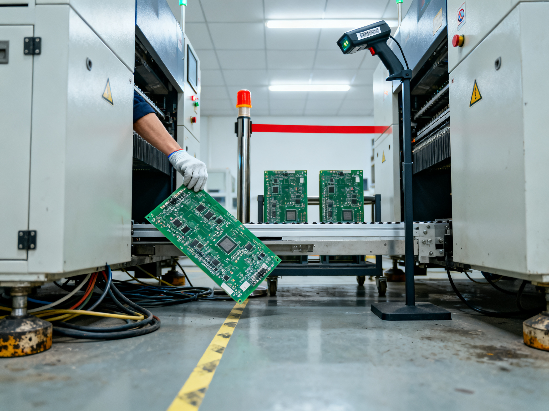
Here is how the handshake works. Each machine has an upstream and downstream signal. The upstream machine asks if it can release a board; the downstream machine answers only when it is clear to receive. If the printer stops for a stencil check, the signal stops with it, and boards queue in the buffer instead of jamming against the printer.
SMEMA-compatible handshaking is the usual language for these signals. It matters because mixed-vendor lines only interlock cleanly when both ends agree on the protocol. If you are combining an SMT line machine from one supplier with a conveyor from another, confirm the handshake specification before the equipment ships, not after it is installed.
Buffers are what make that possible. A buffer is a short queue of boards between two stations. Its job is to absorb a brief stoppage upstream without starving the downstream machine. The rule of thumb: buffer capacity should cover your longest expected stoppage at the upstream station, plus one board for spacing. Two to three boards per station is common. Buffers also slow the line slightly, so they are not free, but a starved oven or an idle AOI costs more.
Stop gates and reject gates are the physical control points. A stop gate holds a board in place at a station until the operator clears a defect. A reject gate diverts a bad board out of the main flow. If you have no reject path, failing boards end up on a workbench, and your traceability story falls apart.
Board compatibility checklist
Before you commit to a loader and conveyor setup, check these against your worst-case board, not your average board:
| Check | What to confirm | Why it matters |
|—|—|—|
| Board size and thickness | Minimum and maximum supported dimensions, including panelized sizes | Undersized support causes warpage during reflow |
| Board weight | Maximum single-board weight, especially on a pallet conveyor | Heavy panels slip or rock in transfer |
| Warpage limit | Accepted board flatness and supported area | Warped boards jam at guide rails and print unevenly |
| Edge clearance | Minimum gap between board edge and conveyor guide | Tight gaps cause edge marking and board lockup |
| Panel support | Whether rails, carriers, or a supporting bed are needed | Unsupported panels deflect and misregister |
| Conveyor width adjustment | Range of adjustment for different board widths | Fixed-width lines limit future product mix |
| Transfer height and direction | Standard working height and left-to-right or right-to-left flow | Mismatched heights force manual re-handling |
| Handshake protocol | SMEMA or equivalent upstream and downstream signals | Without it, stations cannot interlock safely |
When things jam, start here
| Symptom | Likely cause | Where to look first |
|—|—|—|
| Board skewed on entry | Loader alignment off, magazine loaded crooked, guide rail pressure | Loader registration marks and entry guide rails |
| Board stops short of the station | Transfer height mismatch or sensor position off | Transfer height setting, sensor position |
| Board will not release to next machine | Downstream signal not received, dirty sensor, buffer full | Downstream ready signal and sensor cleanliness |
| Stops at one machine only | That machine is the true bottleneck, not the transfer | Machine cycle data, feeder and nozzle performance |
| Magazine error or miscount | Sensors dirty, wrong frame type, magazine not seated | Magazine sensors and frame type setting |
| Boards arrive out of sequence | Barcode check disabled or reject path not configured | Barcode reader and reject routing |
| Frequent sensor faults | Dust, paste overspray, vibration | Clean sensors, check conveyor vibration mounts |
From the floor: The fastest way to find a board-handling problem is to watch one board travel the whole line with the operator. Do not stand at the machine that alarmed. Stand upstream and watch where the board actually hesitates. The alarm tells you where the line stopped; the board tells you why it was late.
One more practical note. Keep a short spare magazine, a set of guide rails, and one spare board of each active size near the line. When a jam happens at 2am on a Saturday, the fix is rarely a machine part. It is usually a rail, a sensor wipe, or the wrong magazine frame.
If your current transfer setup is the bottleneck, talk with our team at S&M Co. Ltd. about full SMT production line setups with buffering, reject handling, and traceability built in from the start.
5. Small SMT Production Line vs. High-Volume Line Setup
Not every factory needs the same line. A prototyping shop running one board and a plant shipping 40,000 units a week are solving different problems, even though both mount components.
The mistake is picking a machine list based on the machine list of a bigger factory. Sometimes the small SMT production line finishes the job faster and cheaper, and sometimes it becomes the ceiling you have to tear down in a year. Here is how to tell which one you are buying.
Three configurations, side by side
| | Prototype / small SMT production line | Flexible mid-volume line | High-volume line |
|—|—|—|—|
| Best for | NPI, prototypes, low volume, high mix | 50 to 5,000 boards a day, mixed product | 5,000+ boards a day, stable product family |
| Loading | Manual or semi-automatic tray loading | Magazine loader with barcode verification | Fully automated magazine or tray loader |
| Printer | Manual or semi-automatic stencil printer | Automatic printer with 2D/3D alignment and cleaning cycle | Automatic printer with closed-loop SPI feedback |
| SPI | Offline or inline basic 3D scan | Inline 3D SPI with defect library and reject routing | Inline 3D SPI with printer auto-adjustment |
| Mounter | Single fine-pitch mounter, manual programming | One or two mounters, feeder-driven, offline programming | Two or three high-speed mounters, software-driven programs |
| Reflow | Small convection oven, 4 to 6 zones | Multi-zone oven with profile logging | Multi-zone or infrared/convection hybrid with nitrogen option |
| AOI | Manual microscope or offline AOI | Inline AOI with defect library | Inline AOI plus X-ray for hidden joints |
| Unloading | Manual take-off to tray | Automatic unloader to tray or stacker | Automatic unloader with sorting and label routing |
| Staffing | 1 to 2 operators | 2 to 4 operators | Separate material, machine, and quality roles |
| Floor space | About 6 m by 4 m | About 12 m by 6 m | 20 m or more, plus aisles and maintenance access |
| Changeover | Manual, often hours | Program-driven, 30 to 60 minutes | Nested feeders, changeover under 30 minutes |
| Traceability | Paper traveler or basic log | Barcode plus centralized data capture | MES-connected, full lot history per board |
Two things jump out of that table. First, the manual end of the spectrum is not a toy. For NPI and rework, manual loading and manual paste printing give the operator the ability to see and touch every board, and changeover takes minutes rather than an hour.
Second, notice that traceability does not scale down. Even on a two-person line, recording the board revision, stencil, placement program, and reflow profile per lot costs almost nothing and saves arguments later.
Plan capacity with a spreadsheet, not a brochure
Here is a simple model you can actually edit. Start with the theoretical rate, then work down through the factors you can measure.
Effective boards per hour = (theoretical boards per hour) × OEE × yield
Where OEE already includes availability, performance, and quality losses. Add changeover time on top:
Effective boards per hour
  = (theoretical boards per hour) × OEE × yield
  − (changeovers per hour × minutes per changeover ÷ 60)
Worked example. Say the printer and mounter combination can theoretically place 900 boards per hour on your board family. Measured OEE across a real month comes to 62%. First pass yield is 96%. That gives 536 boards per hour before changeovers. Run two changeovers per hour at 40 minutes each, and you lose 1.33 hours. Over an 8-hour shift you get roughly 3,350 good boards instead of the 4,200 the brochure implied.
Now run the same numbers against a slower mounter with faster changeover, say 500 theoretical boards per hour but 15-minute changeovers. OEE might be 75%, yield 98%. Two changeovers per hour costs only 30 minutes. That line comes out ahead for a mixed product schedule. Same product every day? The fast line wins by a mile.
Which is why the honest answer to “small SMT production line or full automatic” depends on your product mix, not your production target.
Expert Tip: Run the capacity model twice before you sign anything. Once with the product mix you have today, and once with the product mix you expect in 18 months. If the modular line still clears your forecast with 20% headroom, modular expansion is almost always the cheaper path, because you avoid paying for capacity you cannot yet use.
When modular expansion beats buying maximum capacity
Modular wins when your product mix is still moving. New designs, new package types, new customers. A modular line lets you add a second mounter, a second SPI, or an inline AOI where the data says the constraint is, instead of guessing at purchase time.
Modular loses when you know the product is stable, the volume is high, and every minute of transfer downtime costs real money. Then buying the higher-throughput configuration up front pays for itself in lost-time savings.
One last thing. Modular expansion is not free. Every added station adds a handshake, a buffer, and a place to jam. Buy the modules, but buy the buffering with them.
Expert Tip: Treat the changeover time as a spec you will test, not a spec you will believe. Ask each vendor for the measured minutes from last product to next on your actual board family, and check whether that number assumes a warm machine and pre-staged feeders.
If you are weighing a mid-volume configuration against a full automatic line, talk with the S&M Co. Ltd. team about scaling an SMT line setup in stages, with the oven, printer, and inspection method held consistent so each added module drops straight into the flow.
Standards still matter at this stage, of course. IPC J-STD-001J with IPC-A-610 covers soldering process control and finished-assembly acceptability, but neither one tells you how many boards to inspect or how fast your line should run.## 6. Integrating Machines, Software, Traceability, and Existing Factory Systems
Here is the thing nobody tells you about buying an SMT production line: the machines are maybe 60% of the work. The other 40% is getting them to talk to each other, to your MES, to your barcode system, and to the data you will be asked for eight months later when a customer asks why board 4412 had a cold joint.
If you have never wired a line into factory systems before, the phrase “line integration” sounds heavier than it is. Here is what actually happens on the shop floor.
What the line-control software actually does
Every SMT line machine runs its own control software. The printer holds paste and stencil recipes. The mounter holds placement programs and feeder verification data. The oven holds thermal profiles. The SPI and AOI hold inspection results. On its own, each of these systems is an island.
Line-control software is the layer that ties them together, and it does a specific set of jobs:
- Recipe management. One product revision maps to a printer recipe, a placement program, a reflow profile, and an inspection setup. Load a board revision and the correct combination travels with it.
- Board tracking. A board is identified at load, and that identity follows it through every station until unload. This is the backbone of lot traceability.
- Feeder verification. The mounter confirms the right feeder sits in the right slot with the right part before the run starts, which removes a whole category of wrong-part errors.
- Alarm and downtime management. Stops get coded and counted so you can see where the minutes actually go.
- Inspection data. SPI and AOI results attach to the board record, not to a separate quality report that nobody reconciles.
- Production reporting. Output counts, cycle times, first-pass yield, and defect paretos come out of the same system rather than three spreadsheets.
Pro Insight: The value of line software is not the dashboard. It is that when a defect shows up at final test, you can pull the paste volume, the placement data, the profile, and the inspection images for that specific board in seconds. If your system cannot do that, you are running a factory, not a controlled process.
How the data actually moves
Most modern SMT lines use the IPC-CFX standard for machine-to-machine communication. CFX defines how equipment exchanges data and instructions over a network, using messages such as CFXP (process data, like a profile or inspection result) and CFXM (materials, like component and paste data). It also supports hermetic, SECS/GEM style communication used in semiconductor environments.
┌──────────────────────────────────────────────────────────────┐
│                    FACTORY LEVEL                              │
│                                                              │
│   ┌────────┐      ┌─────────┐      ┌──────────┐             │
│   │  ERP   │◀────▶│   MES   │◀────▶│ Barcode  │             │
│   └────────┘      └────┬────┘      └──────────┘             │
│                         │                                    │
│              ┌──────────┴───────────┐                        │
│              │   Line-Control SW    │                        │
│              │  recipes, tracking,  │                        │
│              │  alarms, reporting   │                        │
│              └────┬────┬────┬────┬──┘                        │
└───────────────────┼────┼────┼────┼───────────────────────────┘
                    │    │    │    │  (IPC-CFX / SECS-GEM)
        ┌───────────┘    │    │    └────────────┐
   ┌────▼────┐   ┌───────▼──┐ ┌▼───────┐ ┌──────▼─────┐
   │ Printer │   │  SPI     │ │Mounter │ │ Oven / AOI │
   └─────────┘   └──────────┘ └────────┘ └────────────┘
The same diagram in reverse is how legacy equipment joins in. Older machines that predate CFX usually expose something simpler, and here is the honest reality in most factories in 2026:
| Interface | What it is | Typical use | What you get |
|—|—|—|—|
| IPC-CFX | Open standard for connected SMT equipment | New machines from most major vendors | Recipe push, process data pull, board tracking, alarms |
| SECS/GEM | Semiconductor-style equipment communication | Lines serving semiconductor or high-reliability customers | Fuller factory control, tighter host-to-equipment sessions |
| TraysXML | Tray and material handling convention | Loader and unloader exchange | Board orientation and slot mapping between stations |
| Vendor API or middleware | Supplier-specific interface | Older machines, or features CFX does not cover | Custom data pull, usually needs a translator layer |
| Dry contact and IO | Simple electrical signals | Mixed or legacy lines | Up and down signals, stop gates, basic handshake only |
| Barcode and MES | Enterprise layer | Every factory, at some level | Work orders, material issues, finished-goods booking |
Note that dry contact signals and SMEMA-style handshaking from the previous section are the floor, not the ceiling. They make the line run. They do not give you traceability.
Integrating with MES, ERP, and material management
An MES sits above the line and answers questions the line cannot: which work order, which material lot, which operator, which shift, what is the schedule. The ERP handles business transactions, and material management handles reels, paste, stencils, and moisture-sensitive components.
The integration, in plain terms:
- MES sends the work order. Board revision, quantity, route, and required inspection level.
- Material management confirms what is issued. Component lot numbers and paste lot numbers get attached to the board record.
- The line runs and reports back. Board IDs, process data, inspection results, and defect codes.
- Inspection results flow to quality. Rejects get routed, and lot-level data supports escape-rate reporting.
- Finished goods return to ERP. Good board quantity, scrap, and rework quantities.
The part people underestimate is material lot traceability. If a joint fails and you know the paste lot but not the component lot, you still cannot bound the problem. So make sure the line records both, and make sure the feeder verification data survives a feeder change mid-run.
Also watch the ESD and handling side of this. An ESD-compliant line needs a documented program, including grounded personnel and workstations, flooring and footwear controls, protected storage and transport, periodic verification of wrist straps, footwear, surfaces, ionizers, and grounding, and defined handling limits for unpackaged ESD-sensitive devices. A good line-control system can log those checks. Whether yours does depends on the software and the vendor.
A staged approach that actually works
Do not try to connect everything in one weekend. This six-step sequence has survived contact with real factory floors.
Step 1: Audit the interfaces. List every machine, its make, model year, software version, and which protocols it supports. Get the CFX conformance or capability list from the vendor, not just the brochure.
Step 2: Map the data fields. Decide which fields matter to you: board ID, revision, paste lot, stencil ID, placement program, profile name, SPI result, AOI result, defect code, operator. Then check whether each machine can actually supply them.
Step 3: Test the handshakes. Verify board tracking survives a full pass, including a stop, a reject, and a board removed and reinserted. If the ID breaks at the oven, your traceability breaks there too.
Step 4: Validate recipes. Run one board through with each station’s recipe loaded from the host, then confirm what the line reports back matches what the machine actually did. This is where wrong-profile bugs hide.
Step 5: Run pilot lots. Do not go live on the first production order. Run 3 to 5 lots, then compare line-reported yield against your manual count.
Step 6: Document the fallback. Write down, in one page, what happens when the network drops or the host goes down. The line must keep running. Manual paperwork, a defined hold procedure, and a re-entry step for data collected offline are not optional.
Commissioning checklist for line integration
Print this and work down it:
| # | Check | Pass condition |
|—|—|—|
| 1 | Board ID read at load | Every board receives a unique, traceable ID |
| 2 | Revision verification | Mismatched revision blocks the run or flags the board |
| 3 | Recipe pull | Correct printer, placement, profile, and inspection setup load automatically |
| 4 | Feeder verification | Wrong feeder in wrong slot halts the run |
| 5 | Board tracking through pass | ID follows the board through SPI, mounter, oven, AOI, and unload |
| 6 | Profile record | Oven stores and returns the profile actually used for each board |
| 7 | Inspection data link | SPI and AOI results attach to the board record |
| 8 | Material lot capture | Paste and component lots bind to the board record |
| 9 | Alarm and downtime capture | Stops are coded, timed, and attributable to a station |
| 10 | MES round trip | Work order in, results and good quantity out |
| 11 | Offline fallback | Line runs through a host or network outage with a defined procedure |
| 12 | Operator permissions | Setup changes and recipe edits are role-controlled and logged |
If you want a starting point for the hardware side of this, talk with the S&M Co. Ltd. team about SMT production line setups with line-control software, recipe management, and traceability structured from the start rather than added later.
Standards still matter here. IPC J-STD-001J with IPC-A-610 covers soldering process control and finished-assembly acceptability, but neither one defines your inspection percentages, your data fields, or your integration protocol. Those you decide.
7. Reducing SMT Defects in BGA, QFN, and High-Density Assemblies
Here is the hard truth about defects on dense boards: by the time you see them at final test, the root cause is three stations back and two shifts ago. Chasing defects with more end-of-line inspection just means you catch them later and rework them slower. The fix is to move the control loop upstream.
Start with the defect matrix. Most high-density failures fall into a handful of repeatable patterns, and each one points at a specific station.
| Symptom | Likely cause | Best detection point | Corrective action |
|—|—|—|—|
| Insufficient solder on BGA balls | Paste volume too low, aperture worn, stencil misaligned | SPI before placement | Clean stencil, adjust deposit, upgrade aperture design |
| Bridging between fine-pitch pads | Paste spread, low-viscosity paste, board not level | SPI, then AOI | Adjust squeegee speed, control paste temperature, use finer aperture or step stencil |
| Tombstoning on 0201/0402 passives | Placement pressure or offset, unstable paste, high board temperature | AOI | Retune feeder and placement force, control paste viscosity |
| Voiding under a QFN thermal pad | Excessive paste, poor venting, insufficient peak dwell | X-ray | Use stepped or window-pane aperture, lower deposit volume, extend soak |
| Head-in-pillow on large BGA | Weak component solderability, long soak, thermal mismatch | X-ray | Improve paste wetting, check component bake and moisture control |
| Open or non-wet joint | Insufficient heat, poor profile, contaminated pads | X-ray plus profile logs | Re-qualify the reflow profile, improve board cleanliness |
| Skewed or missing component | Feeder error, nozzle wear, placement offset | AOI | Feeder verification, nozzle replacement, placement calibration |
| Solder splash or balling | Paste slump, air voids in jar, vigorous reflow | AOI and line-side checks | Vacuum degas paste, adjust paste thickness, control reflow ramp |
Notice how the right-hand column is mostly process control, not inspection. SPI catches a bad print before a component lands on it. X-ray catches hidden voids before a board ships. But the corrective action lives in the printer recipe, the stencil, the profile, and the feeder setup.
Now, the piece that pulls it all together: a qualified profile is never a fixed number from an oven controller. It depends on your alloy, flux chemistry, board finish, copper distribution, panelization, and component body temperature limits, and it has to be measured on representative assemblies. IPC spells out the process requirements and the finished-assembly acceptability rules, and it also states plainly that IPC-A-610 does not set criteria for X-ray or cross-section evaluation, so those thresholds are yours to define from your own design rules and process data. The IPC J-STD-001J contents outline is worth reading once so you know what the standard does and does not cover for your product class.
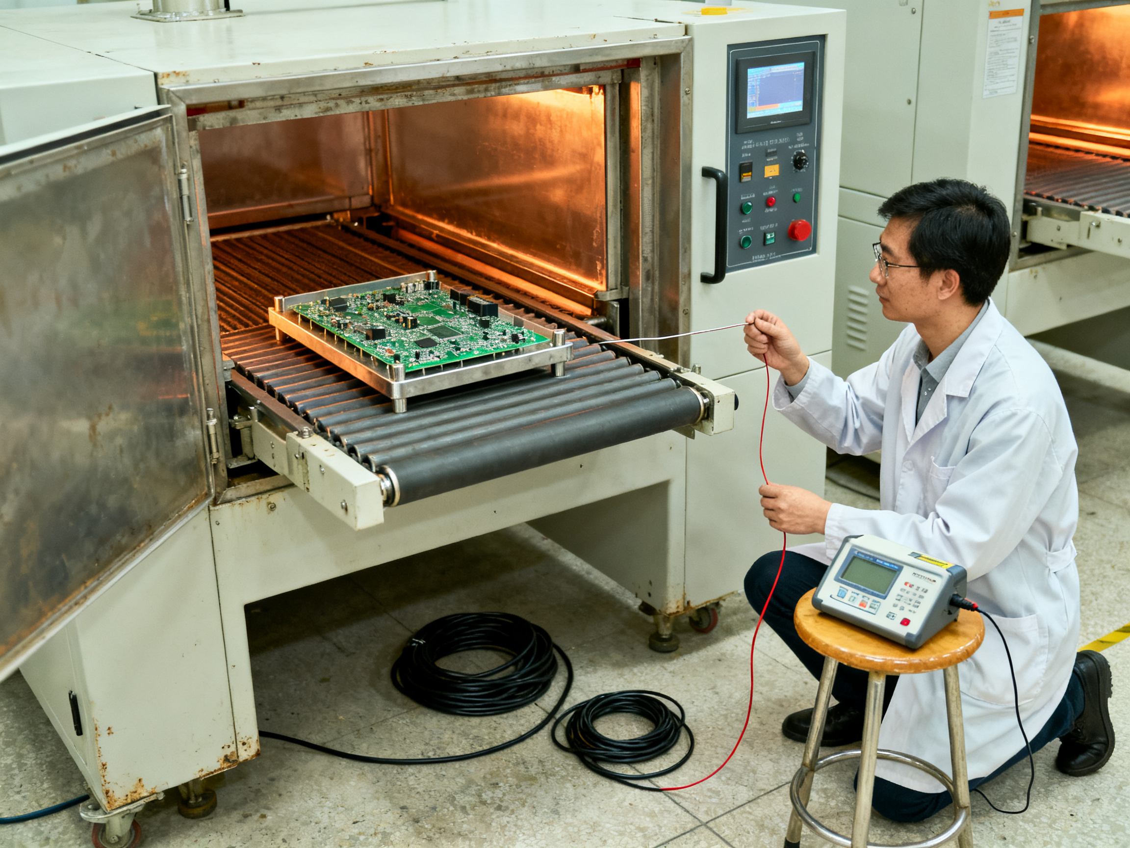
From Our Experience: On one high-density BGA board, first-pass yield sat at 91% with voiding under the thermal pad as the top defect. X-ray confirmed the pattern, and the cause was not the oven. The QFN-style aperture was depositing full volume with no vent path. Switching to a step stencil with a reduced inner deposit, plus a longer soak in the profile, dropped voids from 18% of inspected joints to under 3% and lifted first-pass yield above 98%. The line never sped up. The defect simply stopped happening.
The takeaway is bigger than that one board. Treat SPI, AOI, X-ray, thermal profiling, preventive maintenance, and statistical process control as one system, not a list of separate quality checks. SPC on paste volume, placement offset, and reflow peak temperature over the run tells you when a process is drifting long before AOI starts flagging boards. And when defects do appear, run root cause analysis properly: pull the board record, look at the paste, placement, profile, and inspection history for that specific board, fix the upstream station, then confirm the fix with SPC data over the following lots.
Nothing replaces a controlled process. End-of-line inspection is a safety net, not a plan.
If voiding and hidden-joint defects are eating your yield on BGA and QFN work, talk with the S&M Co. Ltd. team about lead-free reflow ovens with profile logging, inspection integration, and SMT line setups built around closed-loop process control.## 8. How to Choose the Best SMT Production Line Equipment and Setup
Everyone wants the best SMT production line equipment. The tricky part is that “best” depends on what your factory actually makes, so the search usually ends with a comparison sheet instead of a decision.
Start with a requirements checklist, not a price list:
- Board and component range. Smallest and largest board sizes, panelized dimensions, thinnest and thickest boards, and the smallest package you place.
- Product mix. Number of variants per week and how much they change.
- Target throughput. Boards per shift, and peak volume you need to absorb.
- Accuracy and yield. Placement accuracy for your finest pitch, and first-pass yield targets.
- Utilities. Available power, compressed air, nitrogen, floor loading, and exhaust.
- Standards. IPC J-STD-001J with IPC-A-610 for soldering process control and finished-assembly acceptability.
- Software, service, spares, and training. Plus room to expand later.
A weighted vendor scorecard
| Criterion | Weight | What to score |
|—|—|—|
| Fit to your product mix and board range | 25% | Can it run your actual boards, not the demo board? |
| Real throughput and changeover | 20% | Measured cycles per hour on your boards |
| Process control and data capture | 15% | Profile logging, SPI/AOI data, recipe management |
| Service response and spares | 15% | Local technicians, part lead times, training quality |
| Total cost of ownership over 5 years | 15% | Consumables, maintenance, software, staffing |
| Scalability and footprint | 10% | Room to add stations without rebuilding |
Pre-purchase checklist
- [ ] Run a trial build on your own boards
- [ ] Time the changeover from one product to the next
- [ ] Run thermal profiling on a representative assembly
- [ ] Complete factory acceptance testing before shipping
- [ ] Check service response times and spare parts stock
- [ ] Call two or three named references in your industry
The real trap is buying on headline placement speed or lowest purchase price. A cheap mounter that starves for feeders costs more per good board than a steadier one. When you compare the best SMT production line setup options, judge them on good boards shipped per hour after changeovers, downtime, and scrap, because that is the number that shows up in your cost sheet.
Ready to see how a full SMT line setup comes together from printer to unloader? Talk with the S&M Co. Ltd. team about lead-free reflow ovens, inspection integration, and complete SMT production lines for consumer electronics, semiconductor, and military work.## Conclusion: Match the SMT Line to the Product, Process, and Growth Plan
The best SMT production line is not the one with the fastest mounter. It is a balanced system, and every station from loader to unloader has to support the others. Layout, board handling, process capability, inspection, software integration, and service all count. Miss one of them and the line runs at the speed of its weakest link, which is usually the printer or the changeover, not the placement machine.
Before you sign anything, work through this list:
- Document your board sizes, component range, product mix, and volume forecast
- Map the proposed layout, including buffer capacity and reject paths
- Model capacity with OEE, yield, and measured changeover time
- Run trial builds on your own boards, not a demo board
- Validate quality with real thermal profiles plus SPI, AOI, and X-ray checks
- Plan commissioning, training, and spare parts before day one
This recommendation follows from the evidence in this guide, but your own product data should always have the final say.
If you want a second set of eyes on a layout, or a sample board run through a trial build, talk with the S&M Co. Ltd. team about complete SMT production lines for consumer electronics, semiconductor, and military assembly work.