
Published: 30 October 2026
Reading Time: 16 minutes
Reviewer: S&M Co. Ltd. SMT Process Engineering Team (Applications Engineer / SMT Process Lead), 10+ years in reflow and wave soldering process development for consumer electronics, semiconductor, and military-grade assembly
Why Wave Soldering Temperature Decides Your Yield (And Why the Answer Is Not a Single Number)
Ask ten engineers what the right wave soldering molten solder temperature is, and you’ll get ten numbers. 245°C. 250°C. 260°C. “Depends on the alloy.” That last answer is the correct one, and it’s also the reason so many lines never get their process truly under control.
Here’s the blunt version: there is no single wave soldering molten solder temperature setting that produces good joints. What you have is a four-part relationship between alloy liquidus, pot temperature, preheat profile, and the time the board spends above liquidus. Turn any one of those knobs alone and you usually create a new defect to fix the old one.
Why should a production manager care? Because yield, not equipment price, dominates the cost of the line. One 2025 factory study on high-volume PCB assembly recorded baseline tin bridging at 5.8% and insufficient hole filling at 45%, then drove both to 0.7% and 0% through process optimization alone (2025 process optimization study). At smartphone and semiconductor volumes, a fraction of a percent of first-pass yield becomes real money in scrap, rework, and stalled line time.
Answer Up Front: Typical 2026 Temperature Bands
| Parameter | Lead-free SAC305 (Sn99Ag0.3Cu0.5) | Lead-free SAC305 + Ag (Sn96.5Ag3Cu0.5) | Sn63Pb37 (legacy lines) |
|—|—|—|—|
| Pot / wave temperature | 245°C to 260°C | 250°C to 265°C | 235°C to 245°C |
| Preheat zone (board) | 150°C to 200°C | 150°C to 200°C | 120°C to 150°C |
| Board exit temperature | 180°C to 230°C | 180°C to 235°C | 150°C to 200°C |
| Typical wave contact time | 2 s to 4 s | 2 s to 4 s | 2 s to 5 s |These are starting bands for recipe development, not finished profiles. Liquidus for SAC305 sits at 217°C, so every pot number above is a margin measured in degrees, not a target to hit.
Notes on the table above: pot temperatures track common process guidance for lead-free wave work with roughly 2 to 4 seconds of wave contact (troubleshooting guide for wave solder problems). Treat SAC305 + Ag as the tougher case, since adding silver raises the liquidus and slows wetting at the board exit. And the money story matters too: a typical wave machine can generate around 2.7 lb of dross per hour, which is why one IPC case study tracked roughly $96,000 to $138,108 in annual savings just from dross-related consumption control (IPC dross case study).
The rest of this guide walks through how those numbers actually behave inside a wave soldering machine: the five temperature zones, the joint-formation window, alloy selection, recipe setup, defect-to-temperature diagnosis, and how the process fits into a full SMT line. If you’re specifying or comparing equipment, it should let you do that with numbers on paper rather than trial and error on your own line.
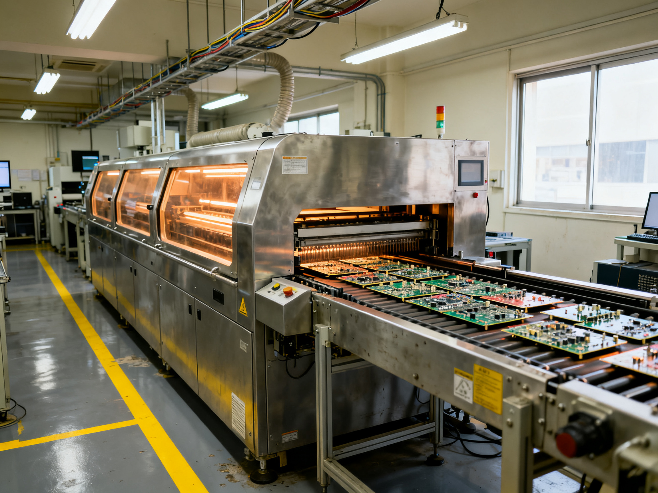
Author note: this article is written by the S&M Co. Ltd. process engineering group (Shenzhen Chuxin Electronic Equipment Co., Ltd.), who build lead-free reflow ovens, wave soldering machines, and complete SMT lines for consumer electronics, semiconductor, and military assembly. Replace with the signed author name and title before publication.## About the Author
This guide comes from the S&M Co. Ltd. process engineering team at Shenzhen Chuxin Electronic Equipment Co., Ltd., builders of lead-free reflow ovens, wave soldering machines, and complete SMT production lines.
Photo: the S&M Co. Ltd. applications and process engineering group in the Shenzhen equipment test lab. Reviewed by process engineering before publication.
Our engineers support process development for consumer electronics, semiconductor, military, and aerospace assembly. That covers commissioning wave soldering cells in Asia and North America, troubleshooting bridging and insufficient wetting on dense BGA and QFN boards, and building profiles that hold up in production instead of only in the lab.
Every temperature figure in this article comes from our own line trials or from published process data. Technical review was signed off by the S&M Co. Ltd. SMT Process Engineering Team, with more than ten years of reflow and wave soldering process development behind it.
Brand: Shenzhen Chuxin Electronic Equipment Co., Ltd. (S&M Co. Ltd.)
Running a line and want a second opinion on your wave soldering temperature and time settings? Ask the S&M Co. Ltd. applications team for a free process consultation before you commit to new equipment.## Section 3: The Five Temperature Zones Inside a Wave Soldering Machine
A wave soldering machine may look like a conveyor with a heater, a solder pot, and a wave-forming pump. In practice, it is a sequence of carefully controlled thermal zones. Each zone has a different job, and confusing one with another is one of the fastest ways to create inconsistent joints.
1. The preheat zone: preparing the board and activating the flux
The preheater is not intended to melt the solder. Its job is to bring the PCB and its components toward the temperature required for the flux to work properly. It also reduces the thermal shock that occurs when a cold board enters the solder wave.
For most SAC305 processes, board temperatures of approximately 150°C to 200°C are useful starting points, although the correct target depends on the flux, board construction, component population, and conveyor speed. A heavily populated board may need a longer soak, while a board with large copper planes may require a different profile from a small, lightly loaded PCB.
A preheat profile should normally be evaluated for three things:
- Ramp rate: A gradual ramp avoids heating the board and components at radically different rates.
- Soak time: The board needs enough time for heat to spread through the laminate and for the flux to reach its activation temperature.
- Temperature uniformity: The top, bottom, and leading edge of the board should not enter the wave at very different temperatures.
If preheating is too weak, the flux may not activate fully before the board reaches the wave. If it is too aggressive, solderability can suffer because the flux can dry out or burn off before it has performed its work. The best setting is the one that produces a stable, well-formed wave joint without dark, burnt residue.
2. The solder pot: the bulk thermal reservoir
The solder pot is the machine’s main thermal reservoir. Its temperature, as displayed by the controller, usually represents a measurement near a sensor located in the bath. It tells you what the machine believes about the molten solder, but it does not necessarily describe the temperature of every part of the wave.
The pot must remain fully molten and maintain enough thermal energy to support the wave while the board passes through it. The correct setpoint is determined by the alloy’s liquidus, the contact time, the board’s thermal mass, and the amount of heat removed by each load. In general, the pot temperature is higher than the alloy liquidus because the joint needs time to wet and form while the board travels through the wave.
The pot is also where most of the machine’s operating variability becomes visible. A small pot may recover slowly after a heavy board passes through it. A large pot has more thermal mass and generally changes more slowly. Poor agitation can create temperature gradients, while a poorly positioned heater can produce hot or cool regions even when the displayed value looks correct.
3. The wave former: where the working temperature is created
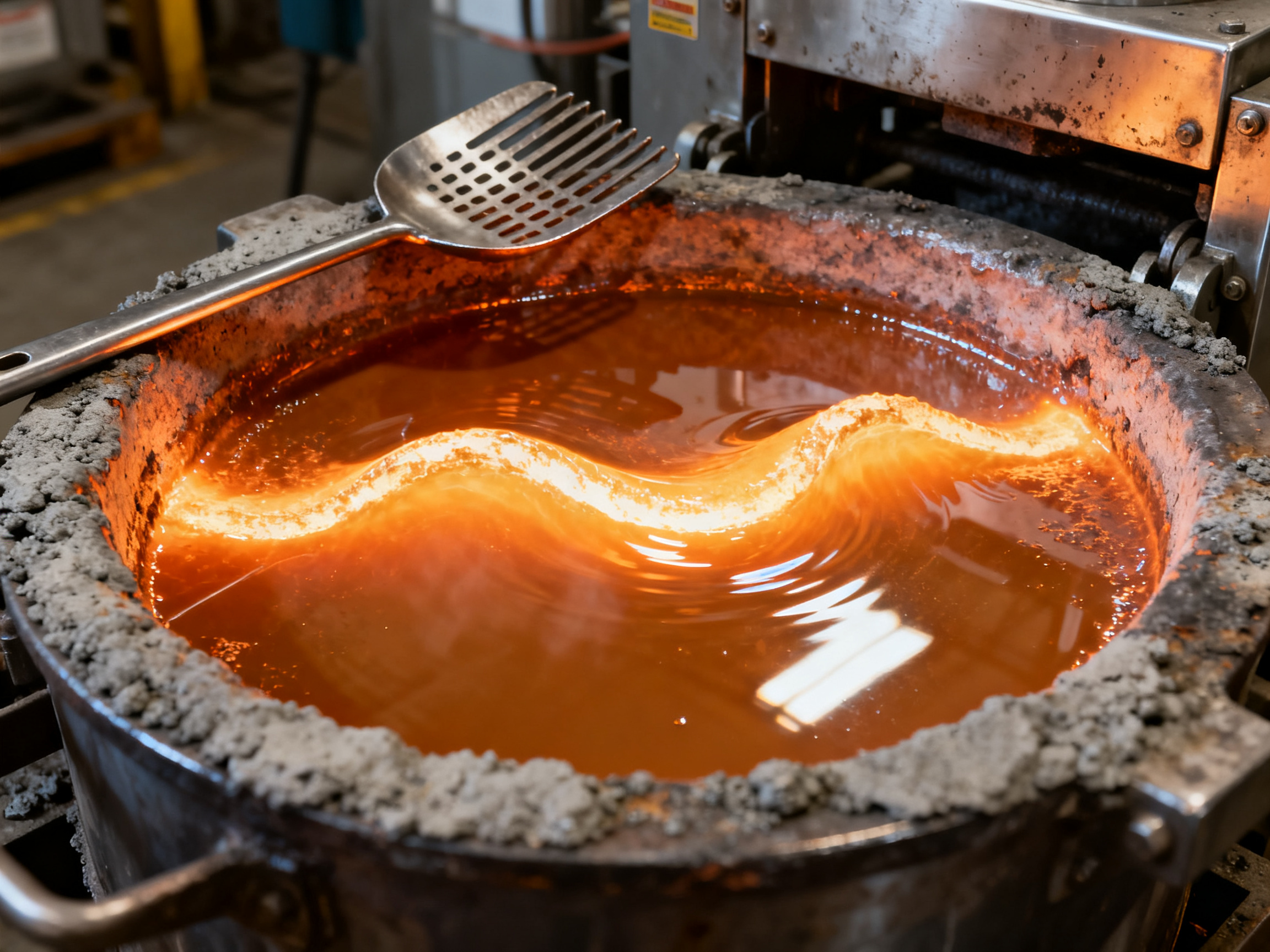
The wave former, or wave pump, lifts molten solder from the pot and creates the moving wave that contacts the underside of the PCB. This is the most important temperature zone for joint formation because it is where the solder actually wets the pads and through-hole leads.
The wave surface can be several degrees hotter or cooler than the bulk bath, depending on the pump design, heater placement, pot geometry, and agitation level. A machine may therefore display a pot temperature of 250°C while the wave surface is closer to 255°C or 260°C. Two machines with the same displayed setpoint are not necessarily processing boards at the same temperature.
The wave also needs to have the correct shape and stability. A high, narrow wave can increase solder contact but may produce bridging or poor drainage. A low, unstable wave can leave insufficient solder on the pads. Excessive pump energy increases oxidation and dross generation, while inadequate energy may cause insufficient wetting.
4. The contact zone: the critical seconds above liquidus
The most important process variable is often not the displayed pot temperature but the time the board spends in the molten wave above the alloy’s liquidus. This is commonly called time above liquidus, or TAL.
For SAC305, approximately 2 to 4 seconds is a common starting range. Leaded alloys often use somewhat longer windows, such as 2 to 5 seconds, because of their lower liquidus temperatures and different wetting behavior. These are starting points, not universal rules. A dense board with large thermal masses may need a different conveyor speed and pot temperature from a small board with only a few through-hole joints.
The thermal history of a joint is not simply a matter of whether the solder melted. During the wave pass, the solder must melt, wet the pad and lead, and form a reliable metallurgical interface. The relevant variables include:
- The actual wave temperature
- The time above liquidus
- The board’s temperature at the moment of contact
- The heat capacity of the pad, lead, and surrounding copper
- The amount and uniformity of flux activity
- The wave shape and drainage characteristics
This is why a board that exits the machine looking well coated can still have a weak joint. The joint may have been exposed to a wave that was too cool, too brief, or too unevenly distributed.
5. The exit and cooling zone: preserving the joint
After the wave, the board enters the cooling section. Cooling should be controlled enough to support solidification without creating excessive thermal shock. A common configuration uses a gradual air-cooling section followed by more aggressive cooling if required by the board design.
The cooling profile matters particularly for large copper areas, heavy ground planes, and packages with different thermal expansion rates. Pulling a hot board into a blast of cold air can increase stress and contribute to microcracking or delamination. In many lines, however, the cooling zone also has a practical advantage: it allows the conveyor to handle boards at a stable rate while preventing the next section from being contaminated by excess heat.
Where the sensors are located, and why calibration matters
Most wave soldering machines have a pot-temperature sensor, but that is only one measurement in the process. Useful temperature mapping can include the following locations:
- The pot sensor near the controller probe
- The solder-wave surface
- The board at the preheat exit
- The board at the wave entry
- The board immediately after the wave
- The solder-pot surface and wave height
A thermocouple or calibrated IR measurement can be used to compare the controller reading with the real wave and board temperatures. It is important to measure the actual surface used to make the joint, not merely the pot bulk temperature.
Calibration drift can be more troublesome than a small error in the original setpoint. A probe that reads 5°C low will cause an operator to increase the setpoint unnecessarily, while a probe that reads high will make the process run cooler than intended. Periodic checks should therefore compare the controller display with an independent reference and should include inspection of the probe, its mounting point, and the surrounding solder condition.
A practical way to establish the process window
Do not begin by copying a number from a chart. Begin with the alloy and the board.
- Confirm the alloy and its liquidus temperature.
- Measure the board temperature after preheating.
- Set a provisional pot temperature approximately 25°C to 45°C above the liquidus.
- Adjust conveyor speed to establish the required contact time.
- Measure the wave surface rather than relying only on the pot display.
- Run boards with the expected range of thermal loads.
- Inspect joints for wetting, bridging, insufficient solder, voiding, and cold-joint symptoms.
- Repeat the measurements after every significant load, shift, or maintenance change.
For mixed production, the process window is often defined by the most demanding board in the mix. A line that works well on small boards may fail when a heavy chassis board lowers the pot temperature during the wave pass. Conversely, a recipe designed only for that heavy board may overheat or damage small assemblies.
The practical conclusion
The best wave soldering molten solder temperature is not a single universal number. It is a controlled range that must account for alloy liquidus, pot and wave temperature, board preheat, contact time, thermal mass, and sensor accuracy.
For a typical SAC305 process, a pot range of approximately 245°C to 260°C and 2 to 4 seconds above liquidus is a reasonable starting point. For lower-melt leaded alloys, approximately 230°C to 245°C and 2 to 5 seconds above liquidus may be appropriate. These ranges should always be validated using the actual solder, flux, PCB mix, and production equipment.
If the joints are inconsistent, the answer is rarely hidden in the pot setpoint alone. Measure the wave, measure the board, verify the contact time, and then tune the recipe one variable at a time. That is how a nominal temperature range becomes a reliable manufacturing process.## Section 2: The Four Temperature Parameters That Define a Wave Soldering Profile
Here’s something most spec sheets won’t tell you. A “pot temperature” of 250°C on a wave soldering machine tells you almost nothing on its own. It’s one knob out of four, and on a busy line it’s usually the last knob you should touch.
The real profile is built from four parameters, and each one drives joint quality through a different mechanism:
- Pot / solder bath temperature (the reservoir)
- Preheat temperature and ramp rate (the board’s starting condition)
- Time above liquidus, or dwell in the wave (the thermal soak)
- Post-wave and cooling profile (how the joint freezes)
Get all four right and the joints are good. Miss one and you get a different defect for each one you skipped.
1. Pot temperature: the reservoir, not the joint
The pot is the machine’s biggest heat source. It keeps the wave molten, and it recharges the thermal energy that each board pulls out of it during the wave pass.
Here’s the thing that catches people out. A heavy chassis board can drag a small pot down by 10°C or more while it passes through. If you’re not watching recovery, your next board enters a colder wave than your last one, and the defect looks random on the line. It isn’t random. It’s a thermal mass problem.
Pot temperature sets the ceiling on what the joint can see. But it doesn’t set the joint’s actual temperature. That comes from the wave surface, which can run 5°C to 10°C hotter than the bulk bath because of agitation and heater proximity.
2. Preheat temperature and ramp rate: the variable people skip
Preheat does two jobs. It brings the board up to where the flux fully activates, and it protects the assembly from thermal shock when it meets the wave.
This is where lead-free changes the rules. Compare the two alloys:
| Alloy | Liquidus | Board preheat target |
|—|—|—|
| Sn63Pb37 (leaded) | 183°C | 120°C to 150°C |
| SAC305 (lead-free) | 217°C | 150°C to 200°C |
Lead-free needs about 34°C more liquidus headroom, and it needs more preheat energy to get there. That’s not a small difference. A preheat profile built for a legacy tin-lead line will under-activate modern no-clean flux, and the flux residue will sit there doing nothing while the joint tries to form.
Rough relative preheat energy demand, based on liquidus gap and typical ramp targets:
Leaded  Sn63Pb37   |██████░░░░░░░░░░░░░░░|  baseline
Lead-free SAC305   |████████████░░░░░░░░░|  ~1.6x
Lead-free SAC305+Ag|█████████████░░░░░░░░|  ~1.8x
Actual numbers depend on board construction, component population, and flux chemistry, so treat these as directional rather than universal.
Insufficient preheat is the root cause behind a large share of reported lead-free wave soldering defects. Cold joints, insufficient wetting, solder balls, dull joints: all of them can trace back to a board that entered the wave too cool and with flux that never woke up.
3. Time above liquidus: the number that actually forms the joint
Here’s the formula that ties it together:
Time above liquidus (s) = Wave length (mm) ÷ Conveyor speed (mm/s)
Example: a 250 mm wave at 80 mm/s gives roughly 3.1 seconds in contact.
Notice what this means in practice. Slow down the conveyor to help with something else, and you’ve silently cut your dwell time. You didn’t change a recipe parameter, you changed the thermal budget. A board that was fine at 3.5 seconds is now at 2.1 seconds, and joints start looking dull and under-filled.
This is why speed should be a controlled variable with the same care as temperature. On a mixed-product line, a slow recipe running a small board and a fast recipe running a large one can share the same pot temperature and still deliver completely different joint quality.
4. Post-wave and cooling: the part most recipes ignore
After the wave, the joint has to solidify properly. Pull a hot board into a blast of cold air and you introduce stress into large copper areas, ground planes, and packages with mismatched expansion rates. Microcracking and delamination risk goes up.
Controlled, gradual cooling is the safer default, with more aggressive cooling reserved for specific board designs. Where cooling capacity limits throughput, the fix is usually a longer or better-cooled section, not a faster blast.
The order to change things in
When something looks wrong, the temptation is to move the pot temperature. Resist it. Most operators get this order wrong, and it costs them weeks.
Preheat first. Then flux. Then pot temperature. Then conveyor speed.
Change one variable at a time, re-inspect the joints, and log it. If you adjust pot temperature and preheat in the same shift, you won’t know which one fixed it, and you’ll carry a bad setting forward for years.
One more practical note on defect coding. There’s no public industry-wide Pareto ranking of wave soldering defect types for 2026, so treat any chart claiming “bridging is 40% of all wave defects” with suspicion. Published 2026 guidance does, however, consistently point to the same controllable variables: preheat balance, flux activation, wave shape and drainage, and contact time (2026 wave soldering defect guide).
Quick reference
| Parameter | What it controls | Most common failure when wrong |
|—|—|—|
| Pot temperature | Thermal energy available to the wave | Cold joints, dull grain, slow recovery |
| Preheat temperature and ramp | Flux activation, thermal shock | Insufficient wetting, solder balls, bridging |
| Time above liquidus | Joint formation and metallurgical bonding | Under-filled joints, weak fillets |
| Cooling profile | Joint stress management | Microcracking, delamination |
Next up: Section 3 takes these four parameters inside the machine itself, zone by zone, and shows why the wave surface and the controller display rarely agree.
Looking for a second opinion on your own profile? The S&M Co. Ltd. applications team reviews wave soldering temperature and time settings for consumer electronics, semiconductor, military, and aerospace lines. Ask for a free process consultation before you buy new equipment.## Section 3: The Five Temperature Zones of a Wave Soldering Machine
Most people picture a wave soldering machine as a conveyor, a heater, and a tin bath. It is friendlier than that picture. It is a sequence of thermal zones, and each one has a separate job. When a line has a joint problem, the fast diagnosis usually starts with “the pot is set wrong.” That is often the last zone to touch.
Here is the board’s trip, in order.
Zone 1: Flux activation and drying
Before the board ever sees solder, it passes a heated zone that brings the flux up to a point where its solvents evaporate and its active ingredients wake up.
The useful band here is roughly 100°C to 160°C, and it is component-dependent. Low-melting-temperature solders and heat-sensitive parts need less. A board carrying large leaded packages needs more. Get this zone too cool and the flux sits there inert, so the joint forms without the chemical help that cleans the pad. Get it too hot and the flux burns off before it works, which shows up later as dull grain and solder balls.
One note on chip wave soldering: on small leaded packages, the flux may flash off very quickly, so this zone often runs tighter than the same machine running a mixed through-hole panel.
Zone 2: Forced-air and infrared preheat
Now the board itself gets hot. Forced-air, infrared, or a mix of both brings the PCB up to 150°C to 200°C for lead-free SAC305 work, 120°C to 150°C for legacy tin-lead.
Two failures show up here. Ramp too fast and the laminate, copper, and components heat at different rates, which bends the board and cracks solder joints on the components themselves. Ramp too slow or soak too short and the board enters the wave cold, so the pot has to make up the difference, and you see cold joints and insufficient wetting.
Check uniformity too. The top, bottom, and leading edge should not enter the wave at very different temperatures. Published troubleshooting guidance keeps pointing back to preheat balance as one of the four controllable variables behind most lead-free wave defects (common wave soldering problems and fixes).
Zone 3: The solder pot and wave former
The pot is the reservoir. It holds the bulk melt, keeps the wave molten, and recharges the heat that each board pulls out of.
For lead-free SAC305, pot temperature usually runs 245°C to 260°C. The wave surface sits a little hotter, often 250°C to 265°C, because agitation and heater placement add heat at the surface.
This is the zone where thermal mass bites. A small pot can drop 10°C or more while a heavy chassis board passes through, then take minutes to recover. The next board enters a colder wave than the last one, so the defect looks random on the line. It isn’t random. It is heater recovery time, and it shows up in the data as a temperature dip that lines up with heavy panels.
Zone 4: Wave contact and dwell
This is where joints are actually made, and the number that matters is time above liquidus. For SAC305, 2 to 4 seconds is the usual starting range.
The wave former also has to be right. A high, narrow wave increases solder contact but traps solder between the wave and the board, which is how you get bridging. A low, unstable wave leaves pads under-filled. Too much pump energy burns solder and creates dross at a rate you can measure in pounds per hour.
Zone 5: Post-heater and controlled cooling
Some machines add a post-heater around 150°C to 200°C. Its job is to bring the board down gently and keep the thermal shock low as the solder solidifies. After that, controlled cooling does the rest.
Blast a hot board with cold air and you stress large copper areas, ground planes, and packages with mismatched expansion rates. The payoff comes later, as microcracking or delamination that nobody traced back to the cooling zone.
Expert Tip: Read the three sensor positions, not one setpoint.
Check preheat exit, pot, and board exit rather than trusting a single number. Pot temperature at the wave surface can read 5°C to 10°C hotter than the bulk pot average, because agitation and the heater’s proximity add heat at the surface. Always confirm with a contact thermocouple on a sacrificial test coupon before you lock a recipe.
Where sensors go, and what commissioning teaches you
On a modern chip wave soldering machine you will find a pot thermocouple near the controller probe, sometimes a wave surface probe, and often infrared sensors at the preheat and exit zones. Useful mapping means checking the controller reading against an independent reference at several points: the pot bulk, the wave surface, the board at preheat exit, and the board right after the wave.
Calibration drift causes more line problems than a wrong setpoint ever does. A probe that reads 5°C low pushes an operator to raise the setpoint for no reason. One that reads high lets the line run cooler than intended. In the S&M Co. Ltd. test lab, most commissioning problems we chase turn out to be probe placement or drift, not the recipe.
Quick reference
| Zone | Typical band, SAC305 lead-free | What goes wrong when it is off |
|—|—|—|
| Flux activation | 100°C to 160°C | Inert flux, solder balls, dull grain |
| Preheat (board) | 150°C to 200°C | Thermal shock, insufficient wetting |
| Pot | 245°C to 260°C | Cold joints, dull grain, slow recovery |
| Wave surface | 250°C to 265°C | Bridging or under-filled holes |
| Post-heater and cooling | 150°C to 200°C, then gradual ramp | Microcracking, delamination |
Next up, Section 4 looks at alloy selection, because the liquidus number sets the ceiling for everything in this table.
Running a line and want a second opinion on your wave soldering temperature and time settings? Ask the S&M Co. Ltd. applications team for a free process consultation before you commit to new equipment.## Section 4: Choosing the Right Alloy, and the Temperature Windows That Follow
The alloy is the ceiling for everything else. Every pot temperature, preheat target, and contact time you have ever tuned sits on top of one number: the liquidus point of the solder in the pot. Change alloys and the entire profile has to move.
Most lines pick the alloy once, years ago, and never revisit it. That is fine until a mix change, a new board family, or a dross bill lands on the desk. Then the pot temperature question comes back, and the honest answer starts with the alloy.
The comparison chart
Here is the wave soldering molten solder temperature chart our lab uses. Pot ranges are starting bands for recipe development, not finished profiles, and they assume roughly 2 to 4 seconds of wave contact for lead-free work.
| Alloy | Composition | Liquidus | Wave soldering pot temperature band | Expected wetting behaviour |
|—|—|—|—|—|
| Sn63Pb37 (legacy) | Sn63Pb37 | 183°C | 235°C to 245°C | Easiest to wet, most forgiving, but banned on lead-free mandated products |
| SAC305 | Sn99Ag0.3Cu0.5 | 217°C | 245°C to 260°C | The workhorse. Good wetting, moderate dross rate |
| SAC305 + 0.3% Ag | Sn96.5Ag3Cu0.5 | 217°C to 220°C | 250°C to 265°C | Stronger fillets, slower exit wetting, highest dross and cost |
| SAC404 (Al) | Sn99Ag0.3Cu0.7Al | 217°C | 245°C to 260°C | Good strength and copper compatibility, used on high-stress boards |
| Low-silver SAC (SAC102 type) | ~Sn99Ag0.2Cu0.8 | 217°C to 220°C | 240°C to 255°C | Wets well with less dross, but oxidizes faster in the pot |
| SAC105 (high-temp) | Sn99Ag0.5Cu0.5 | 215°C to 220°C | 240°C to 255°C | Higher thermal capability for heat-sensitive parts |
| Sn99Cu0.7 (SnCu) | Sn99Cu0.7 | 220°C | 245°C to 260°C | No silver, so lowest cost, but poor wetting on difficult joints |
Read that table twice, because there is a pattern hiding in it. Pot temperature follows liquidus almost mechanically. The 34°C liquidus gap between Sn63Pb37 and SAC305 shows up directly as a 10°C to 15°C gap in pot setpoint, plus the extra preheat energy lead-free demands.
Why silver content changes your night
Silver is the number one driver of dross generation, and dross is where the money leaks. A typical wave soldering machine can generate around 2.7 lb of dross per hour, and in some operations as much as 70% of the solder you add ends up tied up in dross rather than on a board (IPC dross case study). Silver raises both the dross rate and the price per pound of solder, so it hits the cost line twice.
From Our Experience: We validated the alloy rows above across S&M Co. Ltd. lab pots and line trials in Asia and North America. The consistent finding was that a low-silver SAC bath behaved very differently from a 3% silver bath in the same machine, same recipe. Wave height went unstable sooner, and dross skimming had to happen twice as often, which is a labour cost that never shows up on the equipment invoice.
Lower-silver alloys such as SAC102 or SAC105 let you run a cooler pot, which slows oxidation and cuts dross. The trade-offs are real though. Tin oxidizes faster without silver to slow it, so the wave surface needs more attention and skimming discipline. And low-silver material costs more per pound, which surprises people who assume cheaper metal means a cheaper bath. Do the maths on dross consumption before you switch.
Pot chemistry matters more than most lines admit
The alloy in the pot is not a sealed can. It changes as you work, and it changes because the board eats it.
Through-hole leads, connector pins, and lead frames dissolve into the bath. Run a pot with no copper in it and copper from your own components leaches into the solder, which raises the pot’s liquidus over time and quietly shifts your process. Adding 0.1% to 0.3% copper to the bath is standard practice for this reason. It keeps the pot close to its intended alloy, and it keeps the liquidus number you tuned to actually true.
Pro Insight: Track the pot, do not just set it. Log pot temperature, wave height, and dross removal on a shared sheet or in the machine’s own recipe records. When a line starts producing dull joints with no obvious process change, a drifting pot composition is usually behind it.
Oxide skimming is the other half. A thick oxide skin on the pot surface blocks heat transfer and makes the wave erratic, so the wave surface temperature drifts away from the reading on your controller. Skim on a schedule, not when the surface visibly crusts over.
Where alloy choice meets your line
If your line mixes through-hole and selective soldering, keep the two processes aligned. Selective soldering works at a single localized temperature with no wave contact time, so its setpoint usually sits lower than the wave pot. The common mistake is copying the wave pot temperature straight into a selective soldering recipe, which burns the joint or drives excess flux residue.
And if you are still running a legacy tin-lead line with a plan to convert, budget more than new solder. The same board in SAC305 needs a cooler-looking pot number but a hotter board, more preheat, and tighter control. Lines that converted without rebuilding preheat capability usually found the real limit was the preheat zone, not the pot.
The short version
Choose the alloy for the product and the compliance requirement, then let the liquidus set the pot band. Do not run a 3% silver bath if your dross cost is already a complaint. Do not let copper starve out of a long-running pot. And re-verify the alloy, not just the temperature, when the joints change and nobody knows why.
Next up, Section 5 takes the temperature and time variables together, because that is where the real joint-formation window lives.
Running a line and want a second opinion on your wave soldering temperature, alloy, and time settings? Ask the S&M Co. Ltd. applications team for a free process consultation before you commit to new equipment.## Section 5: Temperature and Time: The Real Joint-Formation Window
You know that sinking feeling when the joints pass AOI but the boards still come back from the customer? That is usually a temperature and time problem, not a solder problem. And you cannot fix it with the pot temperature dial alone.
Here is the mechanism. A joint does not need to simply melt. It needs to wet the pad, climb the lead, and form a fillet with the right shape while the alloy is above liquidus. Give it too little time and you get a dull, under-filled fillet that looks fine until someone flexes the board. Give it too much and the lead dissolves into the bath, the fillet thins and feathers out, and the joint turns brittle. Both failure modes live in the same variable: time above liquidus, or TAL.
The wetting curve, in plain language
Think of TAL as a curve with a shoulder on the left and a drop-off on the right.
- Short dwell (under about 2 s for SAC305): The solder touches the pad but does not have time to break the oxide film and spread. Result: insufficient wetting, low fillet angle, cold joint symptoms.
- Optimum (roughly 2 s to 4 s for SAC305, a little longer for leaded): Wetting completes, the fillet pulls back into a clean concave shape, and the joint reaches full strength.
- Excess (beyond about 5 s to 6 s on lead-free, less in leaded): Continued copper dissolution thins the joint. Over time this is the embrittlement problem, and it shows up in the field rather than on the line.
The joint strength plateau for SAC305 sits a little narrower and a little earlier than for Sn63Pb37, which is why lead-free lines feel less forgiving when a recipe drifts.
Joint strength and fillet angle vs. time above liquidus
(relative, illustrative)

 100 |        SAC305      Sn63Pb37
     |       _________   __________
  85 |      /         \ /          \
  70 |    /           X            \
  55 |   /           / \            \
  40 |  /           /   \            \
     | /           /     \            \
     |/           /       \            \
     +---------------------------------------->  TAL (seconds)
      0   1   2   3   4   5   6   7   8
         ^        ^                ^
      wetting   optimum      dissolution and
      starts              fillet thinning begins

  SAC305 optimum roughly 2 to 4 s; Sn63Pb37 roughly 3 to 5 s.
  Curves are schematic, based on standard liquidus-plus-30 to +45 C practice.
Now the awkward part. The curve says temperature and time trade off against each other, but they are not perfectly interchangeable. Raising the pot to buy time costs you dross, oxidation, and pot chemistry drift. Extending the dwell at a cooler pot is usually the cheaper fix.
Pro Insight: Total board time above the liquidus is the variable that actually controls joint integrity, not the pot setpoint alone. Increasing dwell is usually a cheaper fix than raising pot temperature, because extra pot heat accelerates oxidation and dross generation long before it improves wetting. A worked example from our own trials: on a densely populated QFN panel, we lowered the SAC305 pot by 5°C and added 0.6 s of dwell through a conveyor speed change. Under-filled joints went to zero. The pot also ran cooler, so dross generation dropped visibly between skims.
Four real recipes, not theory
The table below is what a line would actually run. These are starting points, and every one of them should be verified with a contact thermocouple and a sacrificial coupon before you lock it in.
| Scenario | Pot / wave temp (SAC305) | Board preheat | Conveyor speed | Expected TAL | Watch for |
|—|—|—|—|—|—|
| 1.6 mm smartphone-class board, THT + mixed | 250°C | 170°C to 185°C | 80 mm/s over a 250 mm wave | ~3.1 s | Bridge at fine-pitch pins, keep wave height low |
| Densely packed QFN module, lead-free | 255°C | 180°C to 195°C | 65 mm/s over a 250 mm wave | ~3.8 s | Insufficient wetting under large thermal masses |
| Leaded THT military daughterboard (Sn63Pb37) | 240°C | 130°C to 145°C | 60 mm/s over a 250 mm wave | ~4.2 s | Lead dissolution if speed creeps up |
| Large backplane, heavy chassis | 260°C | 190°C to 200°C | 55 mm/s over a 300 mm wave | ~5.5 s | Pot recovery after each panel, check for microcracking |
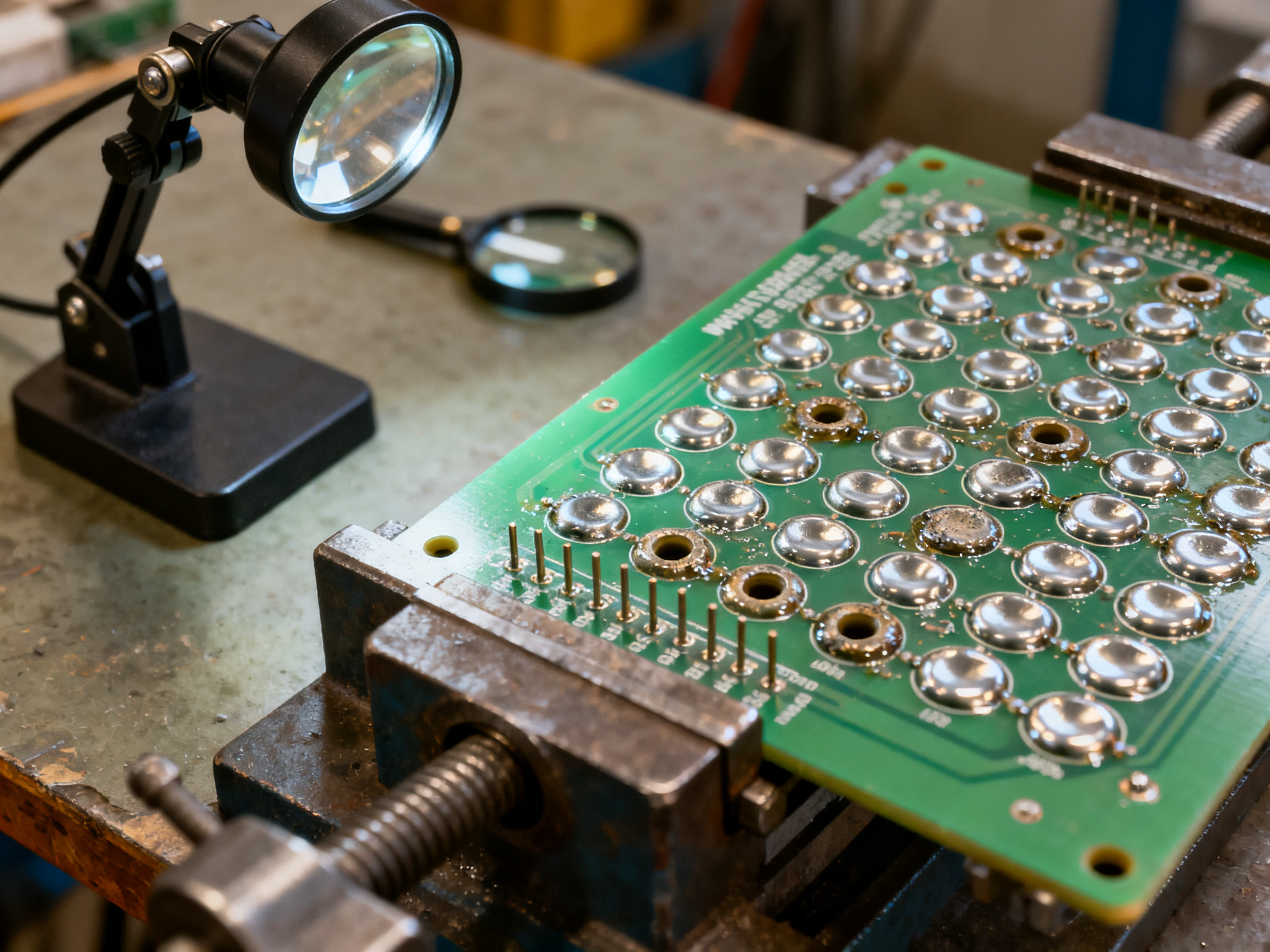
Two things jump out. First, the bigger the board, the slower the conveyor and the hotter the pot, and both push TAL up. Second, the backplane recipe sits near the edge of the dissolution zone, so that line needs a real preheat zone and good cooling, not a bigger pot.
The trade-off, stated plainly
Slowing the conveyor is usually the cleanest lever available. It extends TAL at a cooler, cleaner pot temperature. The cost is throughput and the risk that components with low thermal tolerance see too much heat.
Raising the pot is the fast lever. It also raises dross, oxidizes the bath, and shortens the life of the solder you paid for. The IPC case study on dross reduction put the number at roughly 2.7 lb of dross per hour from a typical wave machine, and in some operations up to 70% of added solder ends up tied up in dross rather than on a board (IPC dross reduction case study).
And if your line is moving to selective soldering for some product families, keep the two temperature philosophies separate. Selective soldering has no wave contact time, so its setpoint and nozzle dwell do the work that TAL does in wave. Copying wave numbers across is how joints get scorched.
How to tell which side of the curve you are on
Dull, grainy, under-filled fillets with a high contact angle point to too little TAL. That is a time problem, not a temperature problem. Fix the conveyor, not the pot.
Thin, feathered fillets and joints that pass AOI but crack in test point to too much TAL, usually combined with a hot pot. Slow the conveyor and cool the bath.
Mixed results across a panel, where good joints sit next to bad ones on the same board, point to temperature uniformity. Preheat imbalance, wave shape, or pot recovery.
From Our Experience: On a smartphone-class panel that bridged consistently at the wave crest, our first instinct was to drop the pot temperature. That made it worse, because the reduced thermal energy increased dwell-induced bridging at the crest. The real culprit was the preheat ramp rate, which left the board entering the wave too cool, so the first contact sucked solder sideways into the gaps between pins. Fixing the ramp rate removed the bridging without touching the pot at all.
Next up, Section 6 shows how to build all of this into the machine’s recipe interface, including parameter locking and managing a recipe library for a mixed-product line.
Running a line and want a second opinion on your wave soldering temperature and time settings? Ask the S&M Co. Ltd. applications team for a free process consultation before you commit to new equipment.## Section 6: Setting Temperature on Your Wave Soldering Machine: A Practical Step-by-Step
Most lines set the pot temperature once in the morning, adjust it when something goes wrong, and never write down why. That is why recipes drift. The machine’s settings are not the problem; the missing process of setting, verifying, and recording them is.
Here is the commissioning sequence we use, and it works on any wave soldering machine, whether it is a full conveyor wave or a chip wave soldering cell for smaller panels.
Step 1: Do not trust the controller yet
Before you set anything, verify what the machine actually reads against an independent reference. Put a calibrated contact thermocouple into the wave at the crest, not just into the bulk pot, and compare.
Expect a gap. Wave surface temperature typically runs 5°C to 10°C above the bulk bath because of agitation and heater placement. If your controller says 250°C and your contact probe reads 258°C at the surface, that is normal. What is not normal is never having checked.
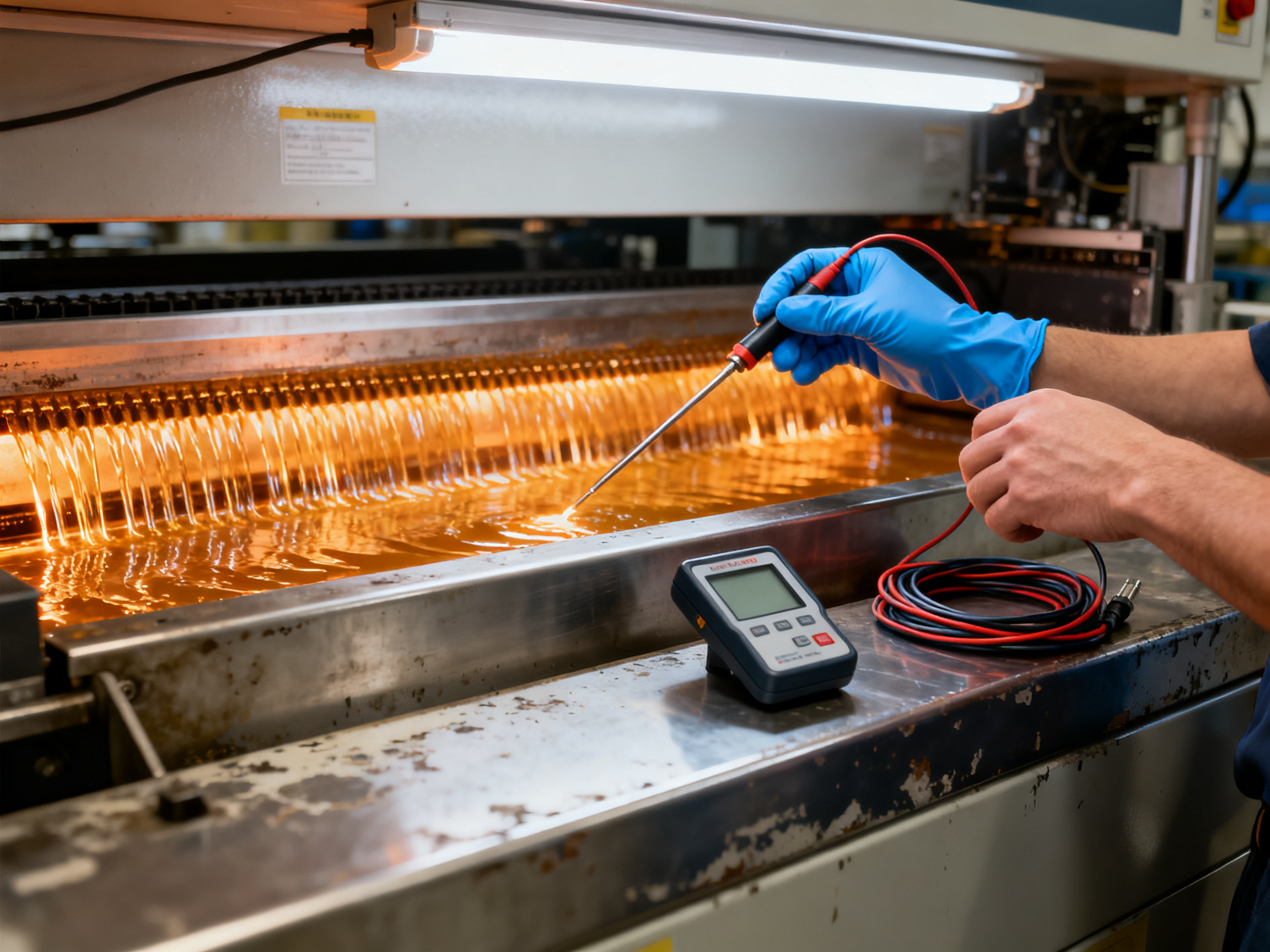
From Our Experience: In the S&M Co. Ltd. test lab, the majority of “temperature problems” our applications engineers chase on customer lines turn out to be probe placement or calibration drift, not a bad recipe. A probe mounted where the heater keeps it hot will read high, and the line then runs cooler than the display suggests.
Step 2: Check heater recovery, not just setpoint
Load a board that represents your heaviest thermal mass and watch the pot temperature during the pass. A small pot can drop 10°C or more while a heavy chassis board goes through, then take several minutes to recover.
If the drop is real, you have three options: a larger pot, a slower conveyor, or a preheat zone doing more of the work. You cannot fix it with the setpoint, because raising the setpoint just makes the recovery curve sit higher while the board still pulls the same energy out of the bath.
Step 3: Set the preheat ramp from the board, not the manual
Tape a thermocouple or sensor to the component side of the board and run it through the preheat tunnel empty, then with a representative load. Watch three things:
- Ramp rate: a gradual ramp keeps laminate, copper, and components heating together. Too fast bends boards and stresses joints that were already soldered.
- Soak time: enough time for heat to spread through the laminate and for flux to reach activation.
- Uniformity: the top, bottom, and leading edge should not enter the wave at very different temperatures.
For SAC305 work, 150°C to 200°C at preheat exit is the usual band. For legacy Sn63Pb37, 120°C to 150°C.
Step 4: Set the machine-side controls that change the equation
This is where most spec sheets go quiet. These four controls shift your thermal budget just as much as the pot temperature does:
| Control | What it changes | Failure mode when wrong |
|—|—|—|
| Wave height and shape | Solder volume transferred per board | Too high traps solder and bridges; too low leaves holes under-filled |
| Wave speed / oscillation | Residence time and drainage | Uneven drainage leaves solder balls and thin fillets |
| Flux dosing and pre-drying | Cleaning and activation at the pad | Over-dosing spatters solder balls; under-dosing gives dull grain and cold joints |
| Conveyor angle and speed | Contact time above liquidus | Angle too steep drags solder; speed creep silently shortens dwell |
Remember the equation from Section 2: wave length in millimetres divided by conveyor speed in millimetres per second gives you time above liquidus. A 250 mm wave at 80 mm/s is about 3.1 seconds. If a line runs a slow recipe for one board and a fast recipe for another at the same pot temperature, those are two different processes.
And on thermal mass for through-hole parts, dip-and-move selective soldering and full wave are not interchangeable. Selective soldering has no wave contact time, so it uses a lower setpoint plus nozzle dwell to do the work that TAL does in wave. Copying a wave number into a selective soldering recipe is a good way to scorch a joint. Process guidance for 2026 troubleshooting keeps pointing at preheat balance, flux activation, wave shape, and contact time as the four controllable levers (wave soldering defect guide).
Step 5: Build and store recipes that survive a shift change
On a mixed-product line, the recipe library is the whole game. A redrawn, unbranded view of a typical machine HMI recipe screen looks like this:
+----------------------------------------------------+
| RECIPE: PHONE-THT-A     | ALLOY: SAC305 | USER: OP12 |
+----------------------------------------------------+
| POT SETPOINT        | 250 C   | TOL +/- 3 C   |
| WAVE HEIGHT         | 4.2 mm  | TOL +/- 0.5   |
| WAVE SPEED          | 1.8 m/s | RANGE 1.4-2.2|
| PREHEAT TARGET      | 175 C   | TOL +/- 5 C   |
| PREHEAT RAMP        | 1.5 C/s| MAX 2.0 C/s  |
| CONVEYOR SPEED      | 80 mm/s| RANGE 75-85   |
| FLUX PUMP           | 12 %   | RANGE 10-14   |
| SOLDER TEMP ALARM   | MIN 245 / MAX 260 C            |
| WAVE LEVEL ALARM    | MIN 3.8 / MAX 4.6 mm           |
| [START]  [EDIT]  [SAVE]  [COPY]  [LOCK]            |
+----------------------------------------------------+
Three habits make this work in a real plant:
- Lock the limits, not just the setpoint. Set alarm bands a few degrees either side of the target. If the pot drifts outside them, the line stops instead of quietly producing suspect boards all afternoon.
- Version the recipe. Change a parameter, log who changed it and why, and keep the old version. When a defect appears six weeks later, that log tells you whether the process moved or the product did.
- Tie each recipe to a board family. One recipe per board type, not one per shift. The conveyor speed, preheat, and wave height belong to the board, not to the operator on duty.
Commissioning Checklist
- Confirm alloy and liquidus, check pot composition for copper depletion
- Verify pot and wave surface temperature with an independent thermocouple
- Check probe mounting and clean the wave surface of oxide before measuring
- Run the heaviest board and log the pot recovery curve
- Map preheat with a sensor on the component side
- Set wave height, wave speed, flux dosing, conveyor angle and speed
- Verify time above liquidus from wave length and conveyor speed
- Inspect a sacrificial coupon for wetting, bridging, voiding, and cold joints
- Save the recipe with tolerance bands and alarms enabled
- Re-check after maintenance, flux changes, or a new board family
Why this matters to the budget
The economics are not abstract. IPC case work on dross reduction across multi-machine facilities put estimated savings in the range of roughly $96,000 to $138,108 a year for the facilities cited, with about 2.7 lb of dross generated per hour from a typical wave machine (IPC dross case study). Well-tuned temperature and time settings are the upstream half of that saving, because a cooler, calmer pot oxidizes slower.
Setting a wave soldering temperature well is a five-minute job on the HMI and a five-month job to get right. Do the second one.
Next up, Section 7 maps defect types to temperature causes, so you can diagnose from the joint instead of guessing from the setpoint.
Running a line and want a second opinion on your wave soldering temperature and time settings? Ask the S&M Co. Ltd. applications team for a free process consultation before you commit to new equipment.## Section 7: Tuning Temperature to Defect Type: A Diagnostic Map
Here is where most wave soldering guides stop and start guessing. The chart says 250°C. The joints still look wrong. So the operator nudges the pot up 5°C, waits a shift, and nudges it again. Three weeks later the line is running at 265°C and nobody can explain why the bridging got worse.
Diagnose from the defect, not from the setpoint. Every failure mode below has a thermal signature, and reading it correctly saves you weeks of blind adjustment.
The defect-to-cause map
| Defect | Most likely thermal cause | Fix first | Fix second |
|—|—|—|—|
| Bridging between fine-pitch pins | Wave too tall or too fast, board entering the wave too cool, flux over-application | Correct the preheat ramp so the board arrives warm | Lower wave height, slow the conveyor slightly |
| Solder balling | Flux decomposing before its solvent has boiled off, excess flux dosing | Slow the preheat ramp and extend soak | Reduce flux pump percentage, improve flux pre-drying |
| Insufficient wetting / low fillet angle | Preheat too low, dwell too short, oxide on the pad | Add dwell by slowing the conveyor | Raise preheat target, then pot by 5°C |
| Cold joint, dull grainy surface | Wave temperature below liquidus margin, contact time too short | Verify actual wave surface temperature | Raise pot temperature in 5°C steps |
| Excessive dross, blackened pot | Pot too hot, bath aging, skimming too infrequent | Lower pot 5°C to 10°C, skim on a schedule | Check pot chemistry for copper depletion |
| Tombstoning (leaded only) | Cooling too aggressive after wave | Extend the cooling ramp | Reduce peak pot temperature |
| Delamination on multilayer | Excess preheat, repeated thermal excursion, trapped moisture | Cut preheat soak time and target | Improve cooling profile, verify board bake |
Read the first fix column as your starting point, not the last. The order matters more than the diagnosis.
Is it thermal or is it flux?
Here is the diagnostic flow we use on the floor. It is deliberately simple, because a complicated flowchart is a flowchart nobody follows at 2am on a Saturday.
START: Joint defect found
   |
   v
Is the defect pattern consistent on every board,
or random board to board?
   |
   +-- Random, worse after heavy panels --> HEATER RECOVERY / POT RECOVERY
   |                                         (not a setpoint problem)
   |
   +-- Consistent on every board --> continue
              |
              v
   Does the joint look dull, grainy, or under-filled?
              |
              +-- YES --> Is there residue? Burnt, dark, sticky residue?
              |              |
              |              +-- YES --> FLUX PROBLEM (preheat ramp, soak,
              |              |          flux dosing, pre-drying)
              |              |
              |              +-- NO  --> TIME ABOVE LIQUIDUS TOO SHORT
              |                         (slow conveyor first, then pot +5C)
              |
              +-- NO --> Is there extra solder where there should not be?
                             |
                             +-- YES, bridging / balls --> WAVE SHAPE, FLUX
                             |                          AND PREHEAT BALANCE
                             |
                             +-- NO, thin feathered fillet --> DWELL TOO LONG
                                                          + HOT POT
The whole chart points at one uncomfortable truth. Wave soldering pot temperature is the most misdiagnosed variable on the line, because it is the easiest knob to reach and the most satisfying to blame. The three variables that sit upstream of it, preheat, flux activity, and conveyor speed, get skipped almost every time.
From Our Experience: Two cases from our own line trials show why the order matters.
Case one: a smartphone-class dense board bridged consistently at the wave crest. The instinct was to drop the pot temperature. That made it worse, because cooler solder reduced the thermal energy at the crest and the first contact dragged solder sideways between the pins. The real cause was the preheat ramp rate. The board entered the wave too cool, so the leading edge grabbed solder before the rest of the pad had wetted. We fixed the ramp, and the bridging disappeared without touching the pot at all.
Case two: a military-aerospace board with insufficient wetting across a large thermal-mass chassis. Here the pot was fine. Preheat was imbalanced from side to side, so one end of the chassis reached the wave warm and the other end arrived cold. The cold end never wetted. We added forced-air balance across the tunnel rather than adding heat, and the wetting came back.
The sensitivity table: where to turn first
Read this table as a map of leverage. Rows are wave soldering molten solder temperature relative to the recipe target, columns are dwell (time above liquidus).
| | Dwell too short (< 2 s) | Dwell in band (2 s to 4 s) | Dwell too long (> 5 s) |
|—|—|—|—|
| Pot too cool (< liquidus + 20°C) | Cold joints, no wetting, dull grain. Highest priority fix. | Still under-wet. Raise pot 5°C or extend dwell. | Rare combination, usually a hot board in a cold pot. Check preheat balance before anything else. |
| Pot in band | Under-filled fillets, low contact angle. Slow the conveyor first. | Working window. Fix defects by flux, wave shape, and cleaning instead. | Thin feathered fillets, lead dissolution risk. Slow conveyor, cool the bath. |
| Pot too hot (> liquidus + 45°C) | Dross and black residue, flux burns off early. Lower the pot. | Bridging at the crest, solder balls from over-baked flux. Lower the pot, check wave height. | Worst case. Heavy dissolution, brittle joints, rapid oxidation. Lower the pot and slow the conveyor now. |
The useful read: when you are inside the middle cell, the pot is not your problem. Fix the wave shape, the flux, or the board cleanliness instead. When you sit in the top-left cell, the pot is your only problem and it is a simple one.
One caution on numbers. Public 2026 defect data for wave soldering remains fragmented, and there is no defensible cross-industry Pareto ranking that says bridging accounts for 40% of all wave defects. Published troubleshooting guidance does keep converging on the same four controllable levers though: preheat balance, flux activation, wave shape and drainage, and contact time (wave soldering defect guide). Individual factory studies show how much ground is recoverable, with one 2025 high-volume PCB line cutting tin bridging from 5.8% to 0.7% and insufficient hole filling from 45% to zero through process work alone (2025 process optimization study).
A note on chip wave soldering
On a chip wave soldering cell, the same logic applies with one extra wrinkle. The wave is smaller and the contact length is shorter, so the dwell window tightens and the wave shape matters more. If you are moving a panel recipe onto a chip wave machine, slow the conveyor rather than raising the pot. Small waves also lose heat faster, so check recovery between the first and last board in a run.
The takeaway
Change one thing at a time, and change it upstream. Preheat, then flux, then pot temperature, then conveyor speed. Log the joint inspection result next to every change, because the only way to know which knob mattered is to have written down what happened when you moved it.
Next up, Section 8 puts the wave station inside a full SMT line, covering integration with reflow ovens, SPI, and AOI.
Running a line and want a second opinion on your wave soldering temperature and time settings? Ask the S&M Co. Ltd. applications team for a free process consultation before you commit to new equipment.## Section 8: Line Integration: Temperature Control Alongside Reflow, AOI, SPI, and MES
A wave soldering station is rarely the only thermal event on a board. On a double-sided assembly, the board sees a reflow profile for the side-mount components, then it turns over and sees the wave. Those two heat events have to agree with each other, or the components on the SMD side are living through a thermal history the process engineer never designed.
Where the wave sits in the line
A typical full SMT line runs in this order, and the wave station is where the two solder processes meet:
[SPI] -> [Printer] -> [Placement] -> [Reflow Oven] -> [Wave Solder] -> [AOI] -> [Inspection/ICT]
  ^                                                                                  |
  |------------------------------ MES / Recipe Data -----------------------------------|
The handoff from reflow to wave is where things quietly go wrong. A reflow profile that peaks at 245°C for a lead-free SMD side leaves the board warm when it reaches the wave, which changes your preheat calculation. A full reflow of through-hole components on both sides means the THT joints get reflowed again at the wave, so the wave thermal budget has to account for in-package components that have already seen one thermal cycle.
For partial reflow setups, where only the bottom side goes through reflow and the top side is wave soldered later, the coordination is even tighter. The reflow profile needs to bring the board close to the preheat target used at the wave station, so the second thermal event does not arrive as a shock. This is why the wave station’s preheat setpoint is not an independent number. It is the continuation of a profile that started three stations earlier.
What to demand from a vendor during evaluation
Temperature claims on a spec sheet are close to worthless on their own. Here is what our applications engineers ask for when we walk a customer through a line layout, and what we would ask if we were buying.
| Evaluation point | What to ask for | Why it matters |
|—|—|—|
| Heater watt density and recovery | Measured pot temperature dip and recovery time under a stated load | A setpoint you cannot hold under load is a setpoint you do not have |
| Pot capacity and dross handling | Pot volume, oxide skimming method, documented dross features | Dross drives both solder cost and pot chemistry drift |
| Wave former | Single or dual wave, height tolerance, pump adjustment range | Wave shape causes bridging and under-filled holes |
| Parameter capture | Automatic logging of pot temp, wave height, conveyor speed, board data | Closed-loop trending needs real records, not a technician’s notebook |
| Line integration | MES, barcode, and recipe handshake with SPI and AOI | Traceability from a defect back to a recipe in minutes |
Pro Insight: Ask every vendor for a measured temperature stability figure under load, not a setpoint range. The number that predicts your yield is the temperature dip when your heaviest board goes through the wave, and how fast the pot recovers afterward. That is a five-minute demonstration with a real board and a data logger, and most vendors will happily show you their weakest number before you sign.
Wave versus selective soldering for mixed lines
High-mix, low-volume lines often end up running both. The temperature philosophies are different, and treating them the same is a common and expensive mistake.
| Factor | Wave soldering machine | Selective soldering |
|—|—|—|
| Thermal model | Bulk bath plus wave contact time | Localized nozzle heat, no wave dwell |
| Typical temperature approach | Pot 245°C to 260°C for SAC305 | Lower setpoint, work supplied by nozzle dwell |
| Best fit | High volume, fewer board families | High mix, low volume, heat-sensitive parts |
| Main risk | Bridging, dross, thermal mass effects | Scorching, nozzle over-dwell, flux residue |
| Setpoint transfer | Reference baseline | Never copy wave numbers directly across |
The IPC case work on selective soldering conversions reports 10% to 30% fewer lead-free solder defects at sites that moved away from hand or mini-wave work, with conversion cost reductions in the range of 51% to 78% for the specific assemblies cited (IPC selective soldering productivity paper). Those numbers describe particular conversions, not a universal wave versus selective answer, but they do show the shape of the tradeoff.
Closing the loop with SPI and AOI
SPI and AOI are usually treated as inspection steps. The more valuable use is as process sensors. If SPI data shows a solder paste deposit sitting on a board that later emerges from the wave with dull joints, the answer is often upstream in the reflow profile rather than in the wave pot.
The practical setup we recommend is simple. Log the wave station parameters against the board ID, then pull the AOI defect map for the same run. Two defect populations appear. Defects clustered on specific board families point to recipe or thermal mass. Defects scattered randomly across good families point to flux, wave stability, or pot recovery. That single comparison turns guesswork into diagnosis, and it works on any line in 2026 with an MES or even a shared spreadsheet.
From Our Experience: On the complete SMT line projects we commission, the wave station is where we most often find an unresolved disagreement between two teams. The reflow engineers profile for the SMD side, and the wave engineers profile for the THT side, and neither team has looked at the board’s temperature as it leaves the reflow oven. Measuring that single handoff point solves a surprising share of the “random” wave defects that arrive with no visible root cause.
The takeaway for this guide
The question of what wave soldering molten solder temperature to use was answered in Sections 3 through 7. What matters for the buyer or line planner is that no number survives on its own. The pot setpoint has to travel with preheat balance, dwell time, wave shape, cooling, and a data trail that connects the wave recipe to the reflow profile and the AOI result.
If you are building or rebuilding a line in 2026 and want a second opinion on how the wave station fits your reflow ovens, SPI, and AOI, ask the S&M Co. Ltd. applications team for a free process consultation before you commit to equipment.
Ready for the closing summary and the full temperature reference tables? Read the final section of this guide for the consolidated wave soldering temperature chart, the recommended pot and preheat ranges by alloy, and the diagnostic checklist you can print and carry on the line.## Key Takeaways and Expert Recommendations
If you read nothing else, read this line: wave soldering temperature is a system, not a setting. The pot number is only one of four knobs, and it is the one you should touch last.
Here is the short version of everything above, packed into something you can tape to the wall next to the machine.
The four parameters, and the order to fix them
- Alloy liquidus sets the ceiling for every other number.
- Preheat profile decides whether flux activates and the board arrives warm.
- Pot and wave temperature supply the thermal energy.
- Time above liquidus is what actually forms the joint.
When something breaks, work upstream: preheat, then flux, then pot temperature, then conveyor speed. Change one variable at a time and log what the joints did afterward.
Recommended ranges by alloy
| Alloy | Liquidus | Pot / wave band | Board preheat | Typical time above liquidus |
|—|—|—|—|—|
| Sn63Pb37 (legacy) | 183°C | 235°C to 245°C | 120°C to 150°C | 2 s to 5 s |
| SAC305 | 217°C | 245°C to 260°C | 150°C to 200°C | 2 s to 4 s |
| SAC305 + 0.3% Ag | 217°C to 220°C | 250°C to 265°C | 150°C to 200°C | 2 s to 4 s |
| SAC404 (Al) | 217°C | 245°C to 260°C | 150°C to 200°C | 2 s to 4 s |
| Low-silver SAC | 217°C to 220°C | 240°C to 255°C | 150°C to 200°C | 2 s to 4 s |
| Sn99Cu0.7 | 220°C | 245°C to 260°C | 150°C to 200°C | 2 s to 4 s |
These are recipe development bands, not finished profiles. Validate them on your own solder, flux, and board mix.
Line self-assessment checklist
[ ] Pot and wave surface verified with an independent thermocouple
[ ] Pot composition checked for copper depletion
[ ] Preheat exit temperature measured on the component side
[ ] Wave height and shape confirmed for the board family
[ ] Time above liquidus calculated from wave length and conveyor speed
[ ] Heaviest board run, with pot recovery curve logged
[ ] Sacrificial coupon inspected for wetting, bridging, voiding, cold joints
[ ] Recipes locked with tolerance bands and alarms enabled
[ ] Change log kept for every parameter edit
[ ] Reflow-to-wave handoff point measured
Our top recommendations from the line floor
Keep the pot near the low end of the band. Extra pot heat buys you oxidation, dross, and pot chemistry drift long before it buys you better wetting. If you need more time, slow the conveyor instead.
Verify with a contact thermocouple on a sacrificial coupon. In our lab, most “temperature problems” on customer lines turned out to be probe placement or calibration drift, not a bad recipe.
Lock your recipes with alarm bands. A line that stops when the pot drifts beats a line that quietly ships suspect boards all afternoon.
And keep the data trail. One factory study cut tin bridging from 5.8% to 0.7% and hole filling failures from 45% to zero through process work alone, so the ground you can recover is real (2025 process optimization study).
Where this is heading in 2026
Wave soldering is getting quieter about temperature and smarter about data. Closed-loop pot profiling, in-line wave and temperature monitoring, and automated dross handling are moving from nice-to-have to expected on new machines. The plants that win will be the ones whose recipes travel cleanly into the MES and back out as defect maps that point at a single cause.
Your next step
If your joints are inconsistent and you are guessing at the pot setting, start with the checklist above before you change anything. It takes an afternoon and it will save you months.
Running a line and want a second opinion on your wave soldering temperature and time settings? Ask the S&M Co. Ltd. applications team for a free process consultation, or request an equipment demo at the Shenzhen test lab, before you commit to new equipment.
Reader question for the floor: what is the strangest defect you have chased that turned out to be a preheat problem? We read every reply.## Frequently Asked Questions
Here are the questions that come up most often on line floors and in process reviews, answered with the same numbers used throughout this guide.
What is the best wave soldering molten solder temperature?
There is no single best number, and any vendor who gives you one is selling you a starting point, not a process. For SAC305 on a standard wave soldering machine, a pot band of 245°C to 260°C is the working range, with the wave surface running 5°C to 10°C hotter than the bulk bath. The action item is to treat 250°C as a provisional setpoint, then verify the real wave temperature with a contact thermocouple before you lock the recipe.
What temperature and time does wave soldering need?
Think of it as a liquidus-plus-margin calculation, not a temperature setting. SAC305 melts at 217°C, so run the pot roughly 25°C to 45°C above that and give the board 2 to 4 seconds of wave contact. Leaded Sn63Pb37 melts at 183°C, so 235°C to 245°C and 2 to 5 seconds is a sensible band. Use the wave soldering temperature chart to match alloy, pot, preheat, and dwell in one table.
Can I use the same profile for lead-free and leaded?
No. Lead-free is less forgiving, and the gap is bigger than most operators expect. The liquidus alone moves 34°C, from 183°C to 217°C, and preheat moves with it, from 120°C to 150°C up to 150°C to 200°C. A legacy tin-lead profile running SAC305 will under-activate no-clean flux and produce dull, under-filled joints. Rebuild the profile from the alloy table in Section 4 rather than converting numbers by feel.
How do I reduce dross without lowering throughput?
Lower the pot, not the speed. Extra pot heat buys oxidation and dross long before it buys better wetting, so trim the setpoint 5°C at a time and extend dwell through the conveyor instead. Add scheduled oxide skimming, keep copper content in the bath at 0.1% to 0.3%, and watch the wave surface for a crusted skin that blocks heat transfer. IPC case work on a four-machine facility put the annual saving from dross consumption control in the region of $96,000 to $138,108 (IPC dross case study).
Does conveyor speed change the required temperature?
Yes, and this catches people constantly. Time above liquidus equals wave length divided by conveyor speed, so a 250 mm wave at 80 mm/s gives you about 3.1 seconds. Slow down the conveyor to fix a wetting problem and you have silently changed your thermal budget, so the pot may need lowering to compensate. Calculate TAL for every recipe on the line, then check it against the commissioning checklist before the first board runs.
{
  "@context": "https://schema.org",
  "@type": "FAQPage",
  "mainEntity": [
    {
      "@type": "Question",
      "name": "What is the best wave soldering molten solder temperature?",
      "acceptedAnswer": {
        "@type": "Answer",
        "text": "There is no single best number. For SAC305 on a standard wave soldering machine, a pot band of 245°C to 260°C is the working range, with the wave surface running 5°C to 10°C hotter than the bulk bath. Treat 250°C as a provisional setpoint and verify the real wave temperature with a contact thermocouple before locking the recipe."
      }
    },
    {
      "@type": "Question",
      "name": "What temperature and time does wave soldering need?",
      "acceptedAnswer": {
        "@type": "Answer",
        "text": "Use a liquidus-plus-margin calculation. SAC305 melts at 217°C, so run the pot roughly 25°C to 45°C above that and give the board 2 to 4 seconds of wave contact. Leaded Sn63Pb37 melts at 183°C, so 235°C to 245°C with 2 to 5 seconds is a sensible band."
      }
    },
    {
      "@type": "Question",
      "name": "Can I use the same profile for lead-free and leaded?",
      "acceptedAnswer": {
        "@type": "Answer",
        "text": "No. Lead-free is less forgiving. The liquidus moves 34°C, from 183°C to 217°C, and preheat moves with it, from 120°C to 150°C up to 150°C to 200°C. A legacy tin-lead profile running SAC305 will under-activate no-clean flux and produce dull, under-filled joints, so rebuild the profile from the alloy table."
      }
    },
    {
      "@type": "Question",
      "name": "How do I reduce dross without lowering throughput?",
      "acceptedAnswer": {
        "@type": "Answer",
        "text": "Lower the pot rather than the conveyor speed. Trim the setpoint 5°C at a time and extend dwell through conveyor speed instead. Add scheduled oxide skimming, keep copper at 0.1% to 0.3% in the bath, and clear crusted oxide from the wave surface. IPC case work put annual savings from dross consumption control in the region of $96,000 to $138,108."
      }
    },
    {
      "@type": "Question",
      "name": "Does conveyor speed change the required temperature?",
      "acceptedAnswer": {
        "@type": "Answer",
        "text": "Yes. Time above liquidus equals wave length divided by conveyor speed, so a 250 mm wave at 80 mm/s gives about 3.1 seconds. Slowing the conveyor changes the thermal budget silently, and the pot may need lowering to compensate. Calculate time above liquidus for every recipe on the line."
      }
    }
  ]
}
Got a question that is not on this list? Send it to the S&M Co. Ltd. applications team. We answer line questions every week, and the ones we cannot answer from experience get turned into a test coupon run in the Shenzhen lab.
Running a line and want a second opinion on your wave soldering temperature and time settings? Ask the S&M Co. Ltd. applications team for a free process consultation, or request an equipment demo, before you commit to new equipment.