
Published: 3 November 2026; last updated 3 November 2026
Reading Time: 16 minutes
Author: (placeholder pending verification)
Reviewer: (placeholder pending verification)
Editorial note: Author name, biography, credentials, and reviewer details remain placeholders. They will be filled in with verified information before this guide goes live.## What a PCB Loader Actually Does
A PCB loader’s job is narrow and mechanical, and it is worth being precise about it because vague specifications are the root cause of most disappointing installations.
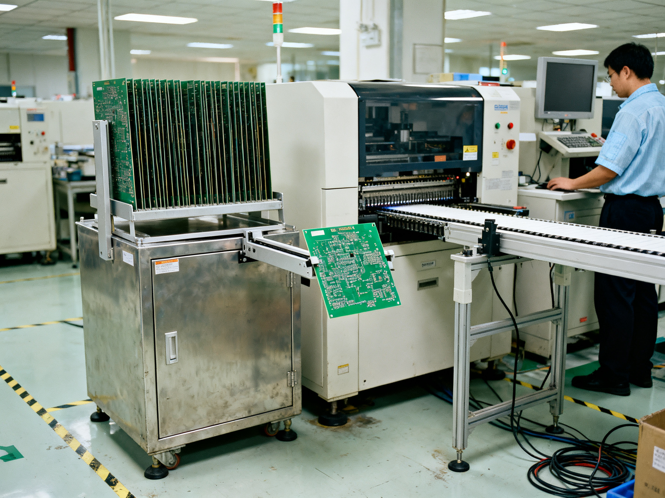
At its core, a magazine loader does four things in sequence:
- Pick — grip a bare PCB from a magazine, tray, or tube without scratching the solder mask, flexing the laminate, or contaminating the contact pads.
- Present — rotate, align, and index the board into the correct orientation and pitch.
- Transfer — place the board onto the conveyor, or hand it off to a downstream buffer, without stopping the conveyor or colliding with fixtures and sensors.
- Signal — confirm placement with sensors or vision so the upstream machine knows a board is present, presentable, and correct.
That last point is the one people skip. A loader is not just a robot arm; it is a source of truth about board presence. If the loader cannot tell the printer or SPI that a board is seated, indexed, and ready, every downstream station starts guessing — and guessing is where cycle time goes to die.
The practical consequence is simple: a well-specified loader is the difference between a line that runs at rated speed and a line that runs at the speed of its least confident operator.
What an SMT Unloader Actually Does
The unloader is the mirror image, with two extra responsibilities that make it the more interesting half of the pair.
It receives finished boards from the exit of the reflow oven or the AOI station and performs:
- Receiving and indexing — picking each board off the conveyor in a controlled, repeatable manner.
- Inspection — optionally verifying placement, solder joint quality, silkscreen presence, or barcode/QR traceability using a light bar, a 2D/3D camera, or an in-line AOI.
- Sorting — routing good boards to a good-board magazine, tray, or pallet, and diverting failures to an NG buffer with a reason code attached.
- Traceability — logging board identity, cycle time, inspection result, and rack position so a recall becomes a lookup instead of a search.
That sorting function is where a modest amount of automation pays for itself fastest. A manual unload station is where good boards get scratched, mixed, and miscounted, and where NG boards quietly make it back into the flow because nobody had time to set them aside properly.
Rule of thumb: if your line still stacks finished panels by hand, you do not have an SMT line — you have a set of very fast machines attached to a manual process.
The Main Types of PCB Loaders
1. Magazine-to-Conveyor Loader (Bare Board Loading)
The classic front-end configuration. The loader pulls bare PCBs from a magazine or ESD-safe tray, aligns them, and places them onto the entry conveyor of the printer or SPI.
Best for: high-mix, high-variety prototyping and small-to-medium batch SMT lines, and any operation where bare boards arrive in racks rather than on pallets.
Typical capacity: 10 to 40 boards per magazine depending on board size and pitch.
Watch for: magazine pitch adjustability. If your boards change thickness or dimension frequently, a fixed-pitch loader becomes an obstacle that operators work around with improvised shims.
2. Conveyor-to-Magazine Unloader
The standard back-end configuration. Boards come off the line, get inspected if inspection is fitted, and are placed into magazines for downstream assembly, testing, or shipment.
Best for: lines running bare-board panels or standard rigid PCBs of mixed sizes.
Watch for: the pick tool. Vacuum cups handle flat, rigid boards well; but fragile, very thin, or very large panels need soft cups, edge gripping, or a dedicated panel gripper.
3. Magazine-to-Magazine Buffer Loader
The loader does not feed the line directly. Instead it transfers boards from an input magazine to an output magazine, creating a decoupled buffer in front of the printer.
Best for: lines with long setup changes, frequent material replenishment, or a downstream process that runs faster than upstream replenishment.
Watch for: buffer size. A buffer of two magazines is not a buffer; it is a delay.
4. SMT Magazine Loader / Post-Placement Loader
This configuration handles boards after pick-and-place but before reflow, transferring them from a magazine or conveyor into the reflow oven conveyor or a side-load conveyor, often in panel form.
Best for: lines with a conveyor gap, a conveyor that is too long for the oven, or a side-load oven whose rails cannot accept the main conveyor.
Watch for: heat and ergonomics. Reflow-adjacent equipment lives in a hot zone; the loader frame, motors, and sensors must be rated for it, and the cabinet electronics need cooling.
5. Conveyor Elevator and FIFO Buffer
Not a pick-and-place loader at all, but routinely listed alongside them because it solves the same problem: keeping the conveyor fed. A FIFO buffer stores boards in a vertical stack and returns them one at a time, or an elevator lifts them between two conveyor heights.
Best for: lines with manual breakaway sections, rework loops, or inspection steps inserted mid-line.
6. Robot or Truss Cell Loader
A six-axis robot or gantry picks boards from trays, tubes, or magazines and loads them into a conveyor, oven, or fixture. Slower than a dedicated loader but far more flexible.
Best for: high-mix low-volume work, mixed board families, and operations where a single cell must handle boards, trays, tubes, and panels.
Watch for: programming effort and cell guarding requirements. Robot cells carry a meaningful safety and validation burden.
7. Tray, Tube, and Panel Loaders
Dedicated machines for specific formats: pick from a JEDEC tray, extract from an antistatic tube, or handle a large panel with a gripper that engages multiple boards at once.
Best for: contract manufacturers with diverse customer packaging, and LED or display panel work.
Watch for: format changeover time. If your business changes board families ten times a week, a machine that takes two hours to retool is a machine that will be retooled once and then ignored.
The Main Types of SMT Unloaders
| Unloader type | Input | Output | Typical use case |
|—|—|—|—|
| Magazine unloader | Conveyor | Magazine | Standard rigid PCB lines |
| Buffer unloader | Conveyor | FIFO stack or magazine | Feeding an assembly or test cell |
| Tray unloader | Conveyor | JEDEC tray | Kitting, depanelisation, programming |
| Tube unloader | Conveyor | Antistatic tube | Small boards and high-mix prototype work |
| Panel unloader | Conveyor | Pallet or stack | Large panels, LED, module assembly |
| Robotic unloader cell | Conveyor | Trays, totes, pallets | Flexible, mixed-format output |
| Inline inspection unloader | Conveyor | Magazine plus NG buffer | Full traceability and sorting |
Note the pattern: the more formats you run, the more you need flexible robotic handling; the narrower your product set, the cheaper a dedicated machine becomes.
Configuration Options That Decide Whether You Like the Machine
Handling and Compatibility
- Conveyor width and board overhang — state the maximum board dimensions, not just the conveyor width. A conveyor of 450 mm can still handle a 500 mm panel if overhang is allowed, but only if the machine was designed for it.
- Board thickness range — thin boards (< 0.8 mm) need different grip and support than standard 1.6 mm laminate.
- Magazine capacity and pitch — specify both, and specify how many magazine positions the machine holds (single magazine, dual magazine, or carousel).
- Component and clearance height — low-profile components, tall connectors, and bottom-terminated parts all change what the pick tool can do.
- Panel support — fragile panels need support rails under the board rather than pickup from one edge.
Sensing and Verification
- Presence sensors on both entry and exit, with PLC logic that refuses to advance on a false signal.
- CCD or 2D vision for index verification and skew correction; 3D vision where component height or warpage matters.
- Light bar plus AOI for solder joint and silkscreen verification before the board is boxed.
- Barcode and QR reading at load, at inspection, and at unload, with the data written to a MES or traceability database.
- NG buffer with reason codes — an NG lane that only holds boards is a bin; an NG lane that records why is a quality system.
Software and Integration
- PLC platform and HMI — ask which one, and ask whether recipes can be created by the operator or require an engineer. On a high-mix line, restricted recipe editing is a hidden tax on every changeover.
- Machine-to-machine communication — SMEMA, SECS/GEM, or a dry-contact handshake at minimum; verified I/O lists matter more than marketing language.
- MES/ERP integration — including how the line reports board counts, cycle times, downtime reasons, and material consumption.
- Remote diagnostics and logging — being able to see why a machine stopped at 02:00 from a phone is worth real money.
- Recipe management and version control — with an audit trail of who changed what.
Mechanical, Electrical, and Compliance
- Machine footprint — including the space needed to open a magazine door, pull a maintenance panel, or load a pallet.
- Weight and floor loading — relevant if the machine sits on a mezzanine or a raised platform.
- Power supply and voltage — plus whether it runs on 220 V, 380 V, or both without a transformer.
- ESD compliance — grounded racks, conductive trays, ionisation where required, and an ESD audit of the whole path, not just the machine.
- Safety guarding — interlocked access, emergency stops reachable from the operator’s normal position, and lockout/tagout provisions.
- CE, UL, or local certification — and whether the supplier provides the technical file.
- Noise level — for operators working eight hours a shift next to the machine.
- Serviceability — availability of spare parts, standard components, and documented self-diagnostics.
Support and Lifecycle
- Warranty — length, coverage, and whether labour is included.
- Spare parts list and lead times — the top ten parts, their price, and expected delivery.
- Installation and commissioning — including on-site training for operators and maintenance staff.
- Mean time to repair — ask for reference sites and actually call them.
- Software support lifetime — how long will the HMI and recipe software be supported?
A Specification Framework for Talking to Suppliers
Do not ask for a price against a part number. Ask for a price against a handling specification. The following is a workable template to send to every supplier so that responses are comparable.
Board handling specification (to be completed by the buyer)

1. Application: [load | unload | buffer]
2. Board type: [rigid | flex | rigid-flex | panel]
3. Board length x width x thickness (min/max): ____
4. Component height range: ____
5. Bottom clearance / tooling clearance: ____
6. Board formats: [magazine | JEDEC tray | tube | pallet | panel fixture]
7. Magazine type, capacity, pitch: ____
8. Conveyor width / pitch / height: ____
9. Required board presentation pitch: ____
10. Target boards per hour (net takt): ____
11. Boards per cycle (single vs multi-board handling): ____
12. Required inspection: [none | barcode | light bar | 2D AOI | 3D]
13. NG handling: [buffer quantity, reason code requirement]
14. Traceability requirement and data destination: ____
15. Operator interface and recipe control: ____
16. Line integration signals required: ____
17. Installation footprint (L x W x H) available: ____
18. Power supply available: ____
19. Ambient conditions / reflow-adjacent heat: ____
20. Certification required: ____
21. Target delivery date: ____
22. Budget range: ____
Then score responses against the same criteria. A cheap machine that cannot hold board skew within the printer’s tolerance is not a cheap machine.
Sizing Throughput: Do the Arithmetic Before You Buy
Most undersized machines are undersized because nobody did the takt math. It takes ten minutes.
- Establish target net takt. If the line must place 45,000 components per hour and your average board has 400 components, the board rate is about 112 boards per hour, or roughly 32 seconds per board. That is your takt time.
- Add changeover and starvation allowances. A realistic factor of 1.2 to 1.5 covers material replenishment, no-loads, jams, and inspection stops. Plan for the worse number.
- Check each station independently. The loader and unloader must each sustain the net takt in their own cycle, including grip, transfer, placement, and confirmation. A loader with a 20-second cycle cannot support a 15-second takt, no matter how fast the placement head is.
- Include buffer time. At least 15 to 30 minutes of buffer at the points where material replenishment happens. Otherwise every magazine change stops the line.
- Verify upstream and downstream capacity. A brilliant unloader feeding a manual assembly station is still a bottleneck at the far end.
Worked example: a line with a 20-second target takt requires the loader to complete a full pick-and-place cycle in under 20 seconds with margin, and the magazine must hold enough boards to cover a full replenishment interval. A 25-board magazine at 30 seconds per board is roughly 12 minutes of run time — which means replenishing three times an hour. That is three interruptions an hour, and it is why magazine capacity deserves more attention than it usually gets.
Common Failure Modes in PCB Handling
The Magazine Is Always Empty
If operators are refilling magazines more than a few times an hour, the machine is undersized, the magazine is too small, or the replenishment procedure is too slow. Fix the buffer first; the loading machine second; the operator third.
Boards Are Scratched or Flexed
Usually a pick-tool or support problem. Soft cups for coated or matte finishes, support rails for large panels, and vacuum level adjustment for thin laminates. Add a rule: no board is ever lifted from a single unsupported edge.
Skew and Index Errors
The loader indexes, but the conveyor does not. Check for conveyor wear, pneumatic pressure drift, and a worn gripper. Index verification with vision turns a silent defect into a visible one.
NG Boards Escape to the Good Magazine
This is a quality escape, not a handling issue. Root causes are unreliable sensing, missing reason codes, or a manual override with no audit trail. Require the NG interlock to be tested as part of acceptance.
Cycle Time Creeps Over Time
Grease, dust, and cable wear. Put preventive maintenance on a schedule with defined tasks — vacuum cup replacement intervals, sensor cleaning, conveyor lubrication, and gripper alignment checks — and track actual board counts per hour as a health metric rather than relying on the hour meter.
Integration Is “Done But Not Really”
The machine raises a done signal, but the line keeps running with an empty conveyor. This is a handshake problem. Agree the I/O list, the handshake timing, and the error states before the machine ships, and rehearse the fault cases during factory acceptance testing.
The Safety Guard Is Bypassed
A guard held open with a cable tie is a machine that will eventually injure someone. Specify interlock monitoring, log bypass events, and include it in operator training.
Building the Business Case
The financial argument for PCB handling automation is usually made in three parts.
Direct labour. The task eliminated — feeding bare boards into a printer and unloading finished boards — is physically repetitive, sits in a hot or noisy environment, and in many regions has high turnover. Automation reduces headcount dependence and, more importantly, reduces the risk of a line going down because three people quit in the same month. Model this as risk reduction, not just headcount reduction; it is the argument that usually wins approval.
Yield and rework. Every manual touch is a chance to scratch, contaminate, or misplace a board. In low-volume, high-value work, one escaped defect can exceed the annual savings from the labour line. For high-mix contract manufacturing, the savings are usually in escaped defects and customer chargebacks rather than in board price.
Capacity and expansion. When a customer asks for more volume, a line with automated handling scales by adding a machine. A line with manual handling scales by adding people and space. This changes how you quote future work, and it is the hardest benefit to quantify and the easiest to feel.
A caution on payback math. Compare the incremental cost of handling automation against the incremental cost of not having it: overtime, training churn, scrap, expediting, and customer penalties. Comparing against the full cost of an SMT line makes automation look trivial, which is not a credible argument. Also model the maintenance and spares cost honestly — a machine with no support plan is a liability, not an asset.
A Vendor Evaluation Checklist
Use a scored list and require every bidder to answer in writing.
Machine capability
- [ ] Cycle time at the specified board size and format, demonstrated on your actual boards
- [ ] Board thickness, size, and panel range fully covered
- [ ] Magazine/tray/tube compatibility, including pitch adjustment
- [ ] Multi-board handling where needed
- [ ] Presence, index, and barcoding verification fitted as specified
Quality and traceability
- [ ] NG buffer with reason codes and automatic NG interlock
- [ ] Recipe storage with version control and access rights
- [ ] Cycle-time, yield, and downtime reporting exportable
Integration
- [ ] Documented I/O list and handshake sequence
- [ ] Verified dry-contact or protocol communication to the printer, SPI, placement machine, and AOI
- [ ] MES/ERP connectivity demonstrated in a factory acceptance test
Compliance and safety
- [ ] CE/UL or equivalent certification with technical file
- [ ] Interlocked guarding, emergency stops, and lockout provisions
- [ ] ESD compliance across the full handling path
Service and economics
- [ ] Two-year parts availability commitment
- [ ] Spare parts list with prices and lead times
- [ ] Installation, commissioning, and operator plus maintenance training included
- [ ] On-site response time and remote support capability
- [ ] Reference site in your region that you can visit
Acceptance testing
- [ ] FAT performed with your own boards and your own recipes, at production volume, not three boards
- [ ] Written FAT protocol covering cycle time, index accuracy, sensor behaviour, and fault handling
- [ ] Warranty starts at SAT, not at shipment
Implementation Roadmap
Phase 1 — Baseline (weeks 1 to 2). Measure the current state honestly: actual boards per hour, manual handling time per cycle, magazine refill frequency, scratch and miscount rates, and operator interventions per shift. Without a baseline you cannot prove a benefit later.
Phase 2 — Specification (weeks 2 to 4). Complete the handling specification template, walk two or three reference sites, and score bidders against the checklist. Send your top two suppliers your actual boards.
Phase 3 — Design review (weeks 4 to 7). Review the layout, conveyor heights, material flow, electrical supply, network access, and safety integration with the machine builder present. Freeze the I/O list here.
Phase 4 — Factory acceptance (weeks 8 to 10). Run the machine with your boards, your recipes, and your cycle-time requirement. Test the failure cases, not just the happy path.
Phase 5 — Installation and SAT (weeks 10 to 12). Install, integrate, train operators and maintenance staff, and run at full takt for a full shift before signing off.
Phase 6 — Optimise (ongoing). Track boards per hour, handling-related defects, replenishment interruptions, and mean time to repair monthly. Most machines are delivered at 85 percent of their rated cycle and can be tuned to 95 percent or better once the real process data is in.
Conclusion
PCB handling is unglamorous work with a disproportionate effect on everything else in the line. The printer, the placement machine, and the oven do the visible work; the loader and unloader determine whether that visible work ever happens on schedule.
The principles that hold across every configuration:
- Specify handling, not equipment. Board dimensions, thickness, format, clearance, and presentation pitch come first; the machine is a consequence.
- Verify rather than assume. Presence sensing, index verification, barcoding, and NG interlocks turn silent defects into visible ones.
- Do the takt arithmetic before the purchase order. A loader one cycle slower than the line’s takt is the constraint on your entire production plan.
- Integrate properly, in writing. I/O lists, handshake timing, fault states, and MES data paths agreed before shipment.
- Test with your own boards. Factory acceptance at production volume beats any brochure.
Get those five right, and the loader and unloader stop being a line of islands and start being the reason the line behaves like a single machine.
Disclaimer: specifications and capabilities described are representative of typical equipment configurations. Performance figures depend on board geometry, cycle configuration, and site conditions; confirm all details against supplier documentation and a factory acceptance test before purchase. Author and reviewer details remain placeholders pending verification.
About the Author
The author details below are placeholders and will be replaced with verified information before this guide goes live.
[Author Name] is a [verified role or credential] with experience in [verified SMT, PCB assembly, automation, or electronics-manufacturing specialty]. [He/She/They] brings [verified achievement, project scope, certification, or years of experience relevant to PCB handling] to this guide.
Work on this PCB loader and unloader guide was built around hands-on shop-floor reality: magazine pitch limits, conveyor height mismatches, index error complaints, and the handshake faults that quietly slow a line down. Where figures appear here, they come from published manufacturer specifications for common 2026 equipment, such as typical magazine capacities of up to 50 boards, selectable 10 mm to 40 mm pitches, conveyor heights around 900 mm to 910 mm, and transfer cycles near 6 seconds per PCB (PCB handling machine specification overview). Every performance claim should still be confirmed against your own boards during a factory acceptance test.
A headshot and a link to a complete author profile will be added here once verified assets are available.
Editor’s note: the author name, biography, credentials, and reviewer details remain placeholders. Verified information will be supplied and this section updated before publication.
1. What a PCB Loader and Unloader Do
A PCB loader is the machine at the front of an SMT line that automatically feeds bare or assembled boards from a magazine, rack, tray, or stack into the line at controlled intervals. A PCB unloader is its partner at the end: it receives finished boards coming off the line, then stores, stacks, sorts, or transfers them onward without upsetting the flow of everything in between.
Put simply, a PCB loader and unloader pair defines the boundaries of your production line. One ends the starvation problem at the front, the other ends the pile-up problem at the back.
Process flow: loader to unloader
MAGAZINE / TRAY
      |
      v
[ BOARD DETECTION ]  --> presence sensor confirms a board is present
      |
      v
[ MAGAZINE POSITION ] --> indexer advances one slot, pitch set to board thickness
      |
      v
[ PUSH / PULL TRANSFER ] --> board leaves the magazine onto the conveyor
      |
      v
[ WIDTH + HEIGHT SET ] --> rails and supports set to board size and clearance
      |
      v
[ PLACEMENT ] --> board indexed and seated on the conveyor
      |
      v
[ HANDSHAKE + CONFIRM ] --> upstream machine told the board is ready
      |
      v
   [ PRINTER ] --> [ SPI ] --> [ PICK AND PLACE ] --> [ REFLOW ] --> [ AOI ]
      |
      v
[ RECEIVE + INSPECT ] --> board taken off the line, optionally checked
      |
      v
[ SORT ] --> good board to magazine, failure to NG buffer with a reason code
      |
      v
MAGAZINE / NG BUFFER / TRAY
Loader vs. unloader at a glance
| | PCB loader | PCB unloader |
|—|—|—|
| Input | Bare or assembled PCBs in a magazine, tray, tube, or stack | Finished PCBs arriving on the SMT conveyor |
| Action | Picks, aligns, indexes, and places boards onto the conveyor | Receives, optionally inspects, sorts, and stacks boards into magazines or trays |
| Output | A steady, confirmed stream of boards feeding the printer | Good boards packed and traceable, NG boards isolated and coded |
| Installation position | Front end, before the solder paste printer | Rear end, after the reflow oven or AOI station |
The operating sequence is where most of the real-world pain lives. Detection, magazine positioning, the push or receive motion, width and height control, the handshake signal to the next machine, the alarm states, and the safe recovery sequence all have to work together. Published specifications for 2026 equipment show the cycle times involved: roughly 6 seconds per board transfer, magazine changeover around 30 seconds, conveyor heights near 900 to 910 mm, and magazine pitches selectable in 10, 20, 30, and 40 mm steps (PCB handling machine specification overview).
Expert Tip: Matching transfer timing and handshake behavior matters as much as nominal loader cycle time. A machine that handles a board every 6 seconds but sends a late “ready” signal will still starve your printer. Write the handshake timing, error states, and recovery rules into the purchase spec, not just the cycle time.
A well-specified SMT loader and its matching SMT magazine unloader turn a collection of fast machines into one line that behaves like a single machine. Get the sequencing right at both ends, and the rest of the line stops guessing.## 2. Main Types of PCB Loaders and Unloaders
Most people picture a PCB loader as a machine with a magazine on top and a conveyor underneath. That picture is only one option, and picking the wrong one is how lines end up with a machine that handles one board format badly instead of the right machine that handles everything well.
The real differences between loader and unloader families come down to five things: where the boards come from, how they are gripped, how they are indexed, how much buffer you get, and what happens to a board that fails inspection.
Equipment comparison at a glance
| Equipment type | Board input format | Best use case | Throughput | Floor space | Advantages | Limitations |
|—|—|—|—|—|—|—|
| Magazine loader | Bare PCBs in magazines | Standard rigid PCB lines, high-mix prototyping | ~6 sec per board, 30 sec magazine changeover | Compact, single footprint | Simple, reliable, cheap to support | Fixed board formats, refill stops |
| Multi-magazine loader | 2 to 4 magazines with lift indexing | Continuous high-volume production with fewer operator interruptions | Same cycle, far longer run time between refills | Taller frame | Cuts interruptions to a few per shift | Higher cost, more complex mechanics |
| Bare board / vacuum loader | Stacked or magazine bare boards | Fragile, coated, or very thin laminates | 6 to 12 sec per board | Compact | Gentle handling, adjustable vacuum | Needs surface support rails |
| Destacker / stacker | Pallets, trays, stacks | Panel and large-format work | Slower, gravity-assisted in part | Needs vertical clearance | Handles heavy panels | Board-to-board spacing is fixed |
| Shuttle conveyor | Any board format moved across the line | Work centres off the main conveyor path | Conveyor speed, ~16 m/min typical | Small footprint | Very flexible, cheap | Adds a transfer point that can jam |
| NG buffer / reject unit | Failures diverted from the line | Any line with inspection | Pass-through when empty | Small | Keeps the main line running | Needs a defined rejection strategy |
| Flip unit | Boards turned over for underside inspection | Double-sided assembly, bottom-side printing | Adds 2 to 4 sec per board | Small | Saves a second pass through the line | Adds a handling touch, so defect risk rises |
| Custom handling module | Whatever the process demands | Military, aerospace, high-density work | Built to the cycle | Varies | Fits unusual formats exactly | No off-the-shelf spares, longer lead time |
Magazine loaders and magazine unloaders
A PCB magazine loader indexes boards out of a rack and pushes or pulls them onto the conveyor. The magazine sits on a lift, the lift indexes one slot, and a push mechanism places the board at the line pitch. Pitch is selectable in 10, 20, 30, and 40 mm steps on most 2026 machines, which matters because pitch must clear component height as well as board thickness.
A multi-magazine arrangement is the upgrade that most high-volume plants want. One magazine sits active on the lifter, one empty waits above, and two full ones wait below, so the machine keeps running while an operator swaps a rack. That layout is standard on modern magazine unloaders, where the same principle removes the manual magazine change from every cycle (multi-magazine unloader configuration).
Pro Insight: Magazine capacity, pitch, lane design, and changeover frequency create hidden bottlenecks more often than cycle time does. A fast machine with a 10-board magazine and a 30-second changeover will lose more time to refills than it saves on transfer speed.
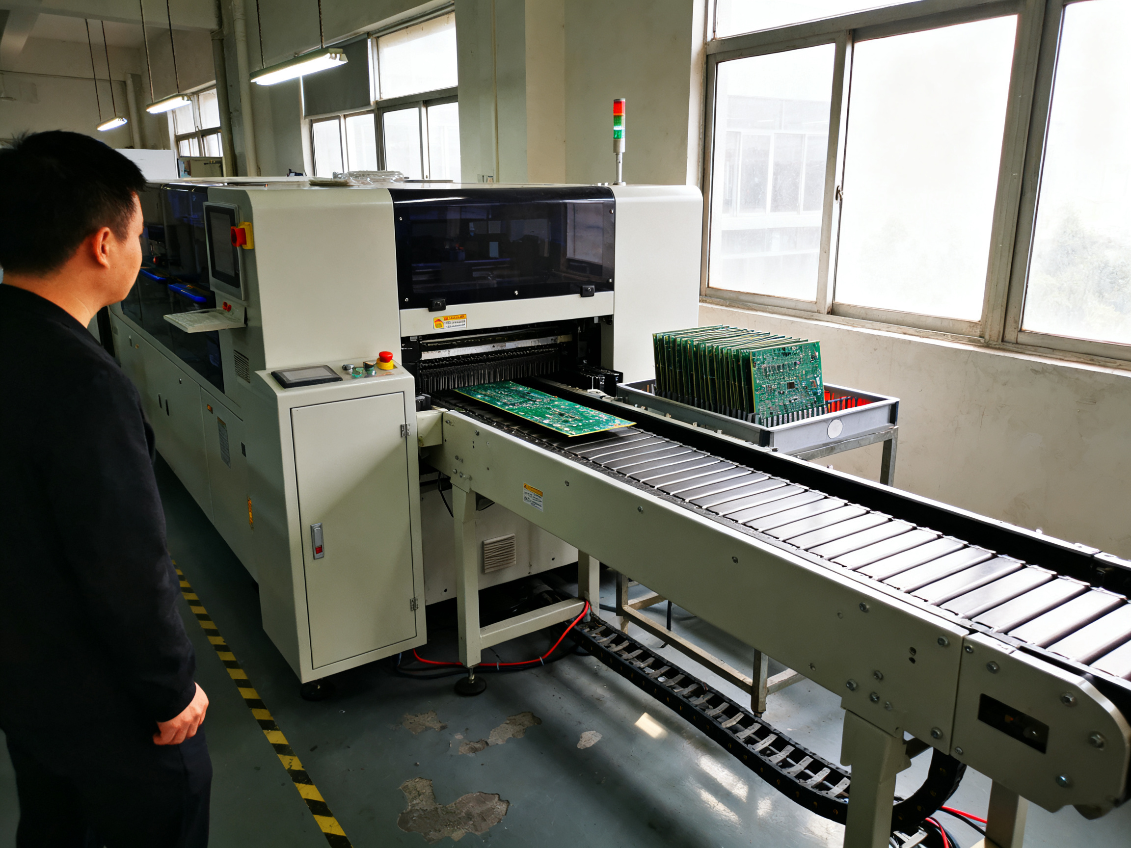
Bare board loaders, vacuum handling, and stackers
A bare board loader is built around a vacuum pick tool rather than an edge pusher. That makes it the right answer for soft finish solder mask, matte surfaces, and thin laminates where a mechanical finger would mark the board. Vacuum level is adjustable, and support rails matter more than most buyers expect: a large panel lifted from one edge will flex.
Destackers and stackers do the opposite job. They take a stack or pallet of panels and present them one at a time to a conveyor or to an operator station. They are slower than a magazine loader but they carry board formats a magazine cannot hold, including heavy LED panels and large module assemblies.
Where the other modules fit
A shuttle conveyor moves boards sideways, usually to reach a selective solder station, an AOI booth, or a rework bench without stopping the main line. An NG buffer is the small protected lane that catches failed boards. A flip unit turns a board over for bottom-side inspection.
Expert Tip: Check board presentation, not just board transfer. On flex and thin rigid boards, the support arrangement under the board often decides whether you get a good board or a scrapped one.
Matching the machine to the board
Application fit is where most of the money gets wasted. Bare boards need gentler handling than populated ones. Single-sided assemblies tolerate a straightforward pick, while double-sided boards need a flip or a second pass. Flex and rigid-flex circuits need support rails and low vacuum, and heavy panels need a gripper that spreads the load across several boards. High-density products with tall or bottom-terminated parts need clearance checked against component height, not just board dimensions.
Sensitive military and semiconductor work pushes one more requirement: traceability. Barcode or QR reading at load, inspection, and unload, written to a traceability database, is not a luxury there. It is the difference between answering a customer question in five minutes and spending a week on it.
Different board conditions, different handling. Get that mapping right and the machine choice writes itself.## 3. Configuration Choices That Determine Line Performance
Two loaders with the same 6-second transfer cycle can behave completely differently on the floor. The cycle time is the headline; the configuration is what actually decides whether the machine keeps up. Published 2026 specifications show the same core transfer rate across most suppliers, with the real differences sitting in board format range, buffer arrangement, and conveyor height customisation (PCB handling machine specification overview).
Magazine architecture and the platforms
A single-magazine machine has one active rack on the lifter. Every cycle ends with the operator swapping in a full magazine and an empty one going back on the machine. With a 30-second changeover and up to 50 boards per magazine, that is a short but constant tax on the line.
A dual or multi-magazine system adds platforms above and below the lifter. One rack sits active, one empty waits above, and two full ones wait below, so an operator swaps racks without the machine stopping (multi-magazine unloader configuration). Some combined loader and unloader cabinets run independent upper and lower magazine conveyors, which doubles the buffer without doubling the footprint.
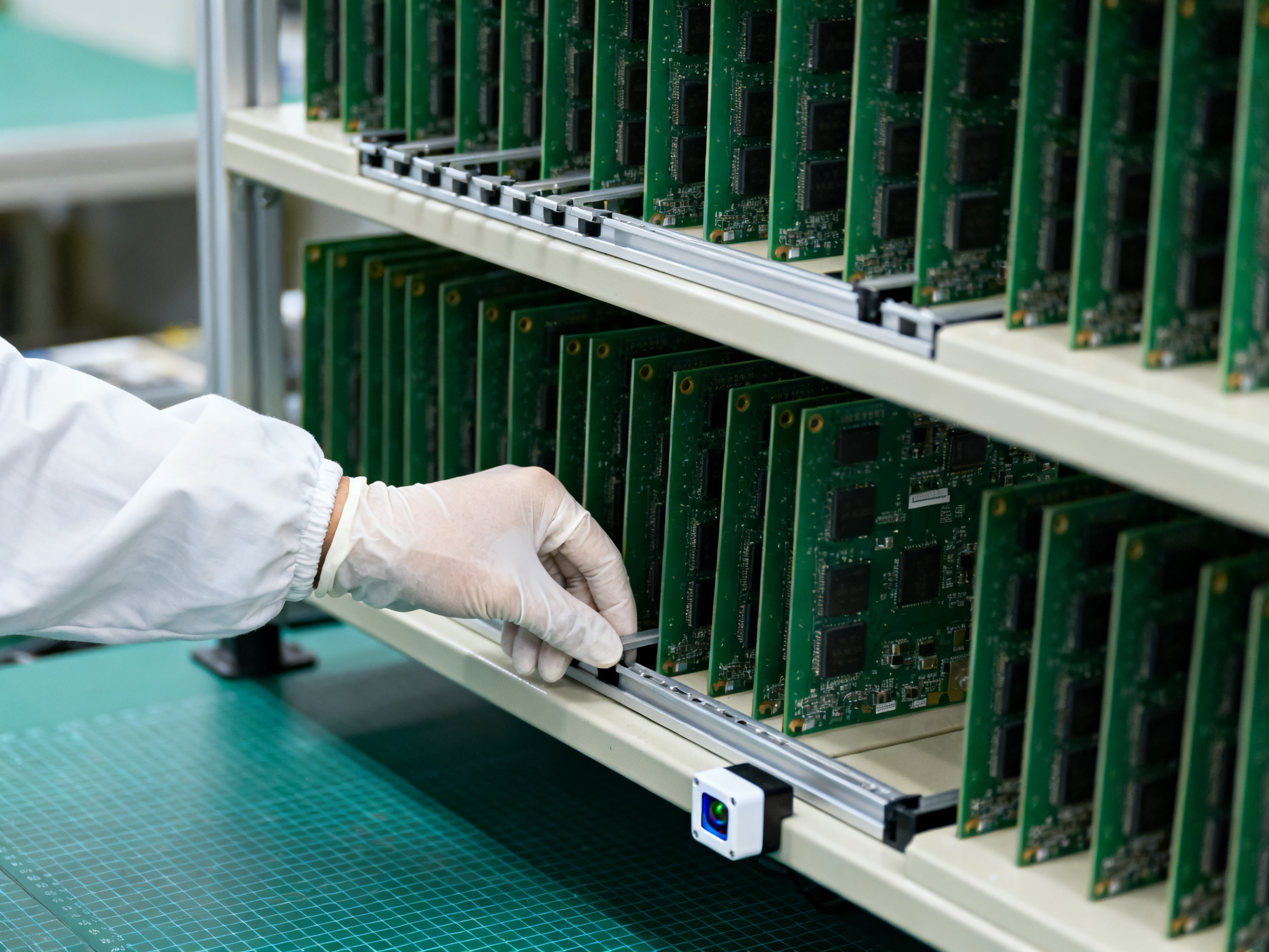
Pitch adjustment belongs in the same conversation. Most 2026 machines offer 10, 20, 30, and 40 mm steps, with some reaching 80 mm. Pitch has to clear board thickness plus component height, not just the laminate.
Configuration decision matrix
| Configuration | Best fit | Buffer | Floor space | Watch for |
|—|—|—|—|—|
| Inline single magazine | Prototyping, low-mix, small batches | Low | Smallest | Frequent refills become the constraint |
| Inline multi-magazine | Continuous high-volume production | High | Tall frame | More mechanics to service |
| Offline (depanelling or kitting adjacent) | Assembly, programming, test cells | Medium | Medium | Board moves off the main path, so traceability must follow |
| L-type | Lines with a corner or return conveyor | Medium | Wide footprint | Turning radius limits long boards |
| Compact | Space-constrained shops | Low | Very small | Limits board size and magazine count |
| Long-board | Panels and large modules | Medium | Long | Rail alignment over full length |
| Dual-lane | Two products alternating on one line | High | Wide | Complexity rises fast, keep recipes simple |
| Custom | Aerospace, military, unusual formats | Variable | Variable | No off-the-shelf spares, longer lead time |
Flow direction, width, and bypass
Left-to-right flow is the default. Right-to-left is available on most machines and sometimes dictated by the building layout or the reflow oven’s oven entry orientation.
Fixed rail width suits a stable product set. Motorized width adjustment pays for itself on high-mix lines, where a rail reset between two board families would otherwise eat a couple of minutes per changeover.
Bypass mode is the underrated one. A bypass lets a board skip a station without stopping the line, which matters during recipe changes, no-load runs, and rework. Ask how a bypassed board is identified in the data record, because a board that skips inspection and still reports as good is a traceability hole.
Worked example: two lines, two answers
A high-mix prototyping shop running 40 board families a week cares about changeover, not raw speed. A 20-second takt, a compact inline magazine loader, and quick pitch adjustment get them through the week. Adding a heavy multi-magazine stack would just be expensive floor space.
A high-volume smartphone or semiconductor plant runs a 4-second takt, holds 20 magazines, and changes product maybe once a week. There, buffer capacity is the whole game. A fast single-magazine loader would starve the printer every 40 seconds.
Same cycle time. Completely different machine. That gap is exactly why you specify configuration, not equipment.## 4. Integrating Loaders and Unloaders With SMT Automation
A loader can perform beautifully in isolation and still starve the whole line. The reason is almost never the pick-and-place motion. It is the conversation the machine has with the printer, the SPI, the placement machine, and the reflow oven. Get that conversation right and the line behaves like one machine. Get it wrong and you get a 6-second transfer cycle feeding a printer that waits 20 seconds for the green light.
The signal flow that keeps a line moving
UPSTREAM MACHINE            PCB LOADER             LINE SIDE
   (printer/SPI)                                    (PnP/oven)

 [ LINE READY ]  ------->  [ MACHINE READY ]  ---> [ LINE READY ]
 [ BOARD REQUEST ] ------>  [ BOARD AVAILABLE ] --> [ BOARD PRESENT ]
 [ LINE STOP ]   <-------  [ FAULT / ALARM ]    <--- [ LINE STOP ]
                  <------  [ CYCLE COMPLETE ]  ---->
In practice this runs on a small set of hard-wired signals. A board-available or board-present signal travels downstream when a board is seated and confirmed. A machine-ready or line-ready signal travels upstream when the machine can accept the next board. A fault signal stops the line safely rather than letting it run on an empty conveyor.
Upstream and downstream handshakes
Most 2026 magazine loaders and unloaders integrate through the SMEMA-style interface, and that remains the baseline for connecting to printers, SPI, placement machines, reflow ovens, and AOI equipment.
The critical detail is the timing, not the wiring. Agree four things in writing before the machine ships:
-
Ready and busy states — what each signal means, and what happens if the upstream machine holds its ready signal low for 90 seconds.
-
Board-available timing — when exactly the loader claims a board is present, before or after the placement sensor confirms seating.
-
Fault and safe-stop behaviour — which faults stop the line, which faults only stop the machine, and how each is cleared.
-
Recovery sequence — what the operator does after a mid-transfer jam, and whether the board position is retained.
-
Downstream handshake — the unloader mirrors the same logic in reverse, with the addition of an inspection decision. A board that fails AOI must be routed to the NG buffer, and the line must not advance until the unloader confirms it took the board. For line-level flow control, conveyor speeds around 16 m/min are typical, and configurable on many models (conveyor and handling specifications).
Mechanical integration across the line
Signal correctness means nothing if the boards do not physically transfer. Conveyor height is the most common mismatch, since 2026 machines typically work at 900 to 910 mm, with some configurations reaching 950 mm. A 30 mm height difference at the loader means the board either scrapes or the operator builds a ramp. Neither is acceptable.
Match the following:
- Conveyor height and flow direction — left-to-right is the default, right-to-left is available on most machines and sometimes dictated by the oven entry.
- Rail width and board support — rail adjustment for board size, and support under large panels so they do not flex.
- Component clearance and overhang — typically around 30 mm, which has to clear tall connectors and bottom-terminated parts.
- End-of-line stations — AOI, the reflow oven exit, wave soldering, depanelisation, and traceability stations all need the same rail geometry and a clean handover point.
Industry 4.0 requirements
Modern lines expect more than a start button. The usual checklist includes:
- Recipe control with version history and operator access rights
- Barcode or RFID tracking read at load, inspection, and unload
- MES connectivity for board counts, cycle times, downtime reasons, and material use
- Alarm history and remote diagnostics so a 02:00 stop can be diagnosed off-site
- Automated product changeover driven from stored recipes
Expert Tip: Ask for the fault case list, not just the working cycle. Any supplier can show a machine placing a board. The ones worth buying are the ones that will show you how it recovers from a jam at step 3 of 7, with the signal timing written down.
Integration checklist
- [ ] SMEMA or protocol interface confirmed in writing, with a signal list
- [ ] Conveyor height, width, and flow direction matched to every adjacent machine
- [ ] Ready, busy, board-available, and fault timing agreed and tested
- [ ] NG buffer interlock proven to stop the line on a fail
- [ ] Barcode or RFID reading points at load, inspection, and unload
- [ ] MES or traceability database path confirmed and tested
- [ ] Alarm history retained and remotely accessible
- [ ] Fault and recovery sequences rehearsed during factory acceptance testing
Most of these lines check themselves once the machine is on your floor. Lines that treat integration as a paper exercise are the ones that discover the problem during a production week. If you want a supplier who will map the whole line rather than drop a cabinet at the end of it, S&M Co. Ltd. and Shenzhen Chuxin Electronic Equipment Co., Ltd. build complete SMT lines with handling, reflow, and wave soldering already speaking the same protocols.## 5. How to Select the Right PCB Loader Unloader System
Buying a PCB loader unloader is easy to get wrong because most comparisons start with price and end with a machine that cannot hold your board pitch. Reverse the order. Start with measurable process requirements, then let the money follow.
Step 1: Define the requirement set
Write down these nine items before you contact anyone:
- PCB dimensions and weight, minimum and maximum, plus thickness range
- Board condition: bare, populated, fragile coating, flex, rigid-flex, or panel
- Target cycle time and the line takt it must support
- Magazine format and capacity the production area actually uses
- Product mix, from one stable product to forty board families a week
- Lane count needed now, and whether a second product must alternate
- Uptime target and how much buffer buys you tolerance
- Component clearance and overhang on the tallest board
- Expansion plans for the next three years
For reference, common 2026 magazine systems handle boards from 50 x 50 mm up to 620 x 460 mm, offer magazine pitches in 10, 20, 30, and 40 mm steps, run a transfer cycle near 6 seconds per board, and sit at conveyor heights of roughly 900 to 910 mm (PCB handling machine specification overview). Match those published ranges against your own numbers and you will immediately see who fits.
Step 2: Score what you cannot see on a brochure
Precision and repeatability, ESD protection along the full path, guarding and interlocks, maintainability and spare parts access, software control depth, documentation quality, service response time, and compatibility with the machines you already own. These are the items that decide whether year three is cheap or painful.
Step 3: Compare total cost, not purchase price
TOTAL COST OF OWNERSHIP (3 YEARS)

  Purchase price
+ Installation, commissioning, training
+ Software licences and MES integration
+ Maintenance contracts and consumables
+ Spare parts held on site
+ Energy use per shift
+ Floor space cost (footprint x rate)

  MINUS
- Labour saved (manual handling hours x loaded rate)
- Defect and rework cost avoided
- Downtime risk avoided (line output x contribution margin)
- Expediting and customer penalty avoidance

= 3-year total cost of ownership
From Our Experience: The single most useful pre-purchase test we know of is a sample-board acceptance run. Send the supplier three of your actual boards, including your widest, your thinnest, and your most awkward with tall connectors. Require a written FAT protocol covering cycle time, index accuracy, sensor behaviour, and fault recovery. Any supplier who refuses to run your boards is telling you something useful.
The specification checklist to send suppliers
PCB HANDLER SPECIFICATION REQUEST

Boards: min/max L x W x T, weight, surface finish
Formats: magazine | tray | tube | panel
Magazine: capacity, pitch range, external dimensions
Throughput: boards/hour at stated board size
Changeover: magazine change time, recipe change time
Conveyor: height, width, flow direction, clearance
Buffer: number of magazines, lane count
Interface: SMEMA signal list + any protocol
Quality: barcode/RFID, NG buffer with reason codes
Compliance: CE/UL, ESD, guarding, emergency stops
Footprint: L x W x H available
Power: voltage, consumption
Service: response time, spares list with prices, training scope
Commercial: price, lead time, warranty, payment terms
Weighted supplier scorecard
| Criterion | Production | Engineering | Procurement | EHS |
|—|—|—|—|—|
| Cycle time and takt match (25%) | 40% | 25% | 10% | 15% |
| Board format and clearance coverage (20%) | 25% | 45% | 15% | 10% |
| Reliability and MTBF data (15%) | 45% | 25% | 10% | 15% |
| Integration and MES (15%) | 25% | 45% | 15% | 10% |
| Service and spares (15%) | 25% | 15% | 40% | 10% |
| Compliance and safety (10%) | 20% | 15% | 15% | 50% |
Have each of your four teams score independently, then compare. The places where production and engineering disagree are usually where the real risk sits, and they are worth 30 minutes of discussion before the purchase order, not after.
When you are ready to talk about a full line rather than a single cabinet, S&M Co. Ltd. and Shenzhen Chuxin Electronic Equipment Co., Ltd. build handling, reflow, and wave soldering stations designed to talk to each other from day one, which removes most of the handshake work described in the previous section.
6. Installation, Operation, and Common Problems
Most PCB loader and unloader headaches show up in the first 48 hours after the cabinet arrives, and almost none of them are about the machine itself. They are about the floor, the utilities, and the handshake nobody rehearsed.
Commissioning, in the right order
Do not rush this. A half-day of careful commissioning saves weeks of chasing phantom faults.
- Verify footprint and utilities. Check the machine sits square, the floor takes the weight, the power supply matches (220 V or 380 V), and the air supply holds pressure. Confirm the clearance needed to swing a magazine door and pull a service panel, not just the machine dimensions on a drawing.
- Align conveyor height and rail width. Published 2026 configurations typically run at 900 to 910 mm, with some reaching 950 mm (single magazine line loader specifications). A 30 mm gap at the handover means scraping boards or building a ramp, and both are unacceptable.
- Validate flow direction. Left-to-right is standard, right-to-left is available on most machines, and the oven entry sometimes decides for you. Confirm before anything is wired.
- Set magazine pitch and board presence. Pitch options typically run 10, 20, 30, and 40 mm steps. Set it to clear board thickness plus component height, not the laminate alone.
- Test the handshake. Walk through every signal: ready, busy, board available, fault. Pull the upstream ready signal low and confirm the loader behaves.
- Run sample boards. Send your widest, thinnest, and most awkward board with the tallest connector. Then run production volume, not three boards.
- Document the acceptance result. Signed, dated, with measured cycle time and index accuracy written into it.
Preventive maintenance
Base the schedule on duty cycle, then follow the manufacturer’s guidance where the two differ.
| Item | Frequency | Note |
|—|—|—|
| Conveyor belts and rails | Weekly | Look for glazing, fraying, and debris |
| Pushers, grippers, clamps | Weekly | Check alignment and wear |
| Sensors and photo-eyes | Weekly | Dust is the usual cause of false signals |
| Magazine lift and rails | Monthly | Lubricate per manual, check for drift |
| Vacuum cups | Monthly | Inspect for tearing; more often on coated boards |
| ESD grounding | Monthly | Verify continuity and rack grounding |
| Safety devices, guards, e-stops | Monthly | Test every interlock, log the result |
| Control software and backups | Quarterly | Archive recipes, review alarm history |
Troubleshooting by symptom
| Symptom | Likely cause | Corrective action |
|—|—|—|
| Board jams at the magazine | Pitch set too tight, or worn pusher | Recheck pitch, align or replace pusher |
| Double feed | Presence sensor weak or misaligned | Clean and re-align sensor, verify PLC logic |
| Poor magazine alignment | Lift index drift or magazine not seated | Re-home the lift, check magazine guide rails |
| Frequent sensor errors | Dust, vibration, loose bracket | Clean optics, tighten bracket, check damping |
| Warped boards flex or snap | Lifted from one unsupported edge | Add support rails, lower vacuum, review pitch |
| Line timing mismatch | Handshake timing differs from agreed spec | Compare actual signals against the I/O list |
| Communication faults | Loose or wrong protocol wiring | Re-terminate, confirm SMEMA or protocol settings |
| Constant operator intervention | Undersized magazine or short buffer | Increase magazine count before buying a faster machine |
Expert Tip: If operators are rescuing boards every few minutes, the fix is rarely in the machine. It is usually magazine capacity, magazine pitch, or a conveyor height mismatch. Fix the buffer first, the loader second, and only then look at the drive settings.
And when the handling cabinets are only one part of a bigger picture, S&M Co. Ltd. and Shenzhen Chuxin Electronic Equipment Co., Ltd. build reflow, wave soldering, and full SMT lines that arrive with the same handling and signalling conventions already in place, which removes a lot of the handshake work from the installation list.
One last thing. Run the line at full takt for a complete shift before you sign off the acceptance sheet. Machines look brilliant in the first hour and reveal their habits in hour eight.## 7. PCB Handling Trends to Watch in 2026 and Beyond
PCB handling in 2026 is heading in one direction: machines that adapt to the product mix instead of forcing the product mix to fit the machine. A plant running 40 board families a week does not need a faster transfer cycle. It needs faster changeovers and a buffer that survives a recipe swap without starving the printer.
Mature now versus emerging
| Capability | Status in 2026 | What it means for your line |
|—|—|—|
| Multi-magazine buffering (4 racks typical) | Mature | Removes the refill stop from most cycles |
| Pitch selection in 10/20/30/40 mm steps | Mature | Covers most bare and populated boards |
| SMEMA handshake with printer, SPI, PnP, AOI | Mature | The baseline interface for the whole line |
| Barcode and QR traceability with NG reason codes | Mature and spreading | Turns a recall into a lookup |
| Adjustable rail width, motorized where volume allows | Mature on premium models | High-mix lines pay back quickly |
| Vision-based index and skew verification | Growing fast | Catches the failures operators used to hide |
| Predictive maintenance on drives, vacuum, and sensors | Emerging | Vendor-dependent, mostly software-led |
| Remote diagnostics with off-site alarm review | Emerging | Lets a 02:00 stop be triaged from a phone |
| Closed-loop takt control across the line | Emerging | Loader and printer negotiate timing automatically |
| Autonomous material movement, AGV and AMR feeding | Early | Still niche outside very large plants |
Published 2026 equipment data shows the mechanical side has largely settled: roughly 6 seconds per board, magazines up to 50 boards, pitch in 10, 20, 30, and 40 mm steps, and conveyor heights around 900 to 910 mm (PCB handling machine specification overview). The variation between suppliers now sits in board format range and buffer arrangement, not in the basic transfer cycle.
So why does modularity matter? Consumer electronics, semiconductor, automotive, military, and aerospace plants all mix older machines with newer ones. A modular handling cabinet that bolts into an existing line and speaks SMEMA lowers upgrade risk, because you replace one station instead of the whole line.
Expert Tip: Ask which parts of the handling system are modular and which are custom. A machine with a custom controller and a proprietary HMI is a 15-year commitment, not a 3-year one.
For buyers assembling full lines rather than single cabinets, S&M Co. Ltd. and Shenzhen Chuxin Electronic Equipment Co., Ltd. pair handling, reflow, and wave soldering stations built around the same signalling conventions, which keeps the integration work described earlier from becoming the bottleneck of the whole project.
Next step: score every trend line above against your own 3-year plan, then keep only the ones that change a purchase decision today. The rest can wait a year.
Conclusion: Build the Handling System Around the Process
Here is the thing people get wrong when they buy PCB handling equipment: they shop by capacity. “How many boards per hour can it do?” is the wrong first question, because every supplier in 2026 publishes roughly the same transfer cycle of about 6 seconds per board, along with magazine pitches in 10, 20, 30, and 40 mm steps (PCB handling machine specification overview). The machines are more alike than the marketing suggests.
What actually decides your line is board format, takt time, product mix, quality requirements, integration standards, and service support. Get those six right and the machine choice takes care of itself.
Your five-step action checklist
- Document the current line honestly. Measure actual boards per hour, magazine refill frequency, scratch and miscount rates, and operator interventions per shift.
- Write a handling specification. Board dimensions and thickness, formats, magazine pitch and capacity, conveyor height, clearance, target takt, inspection and NG requirements.
- Validate with your own sample boards. Send your widest, thinnest, and most awkward board, with a written factory acceptance protocol.
- Test communications before shipment. Agree the I/O list, handshake timing, fault states, and MES data path, then rehearse the failures.
- Compare lifecycle cost, not purchase price. Add spares, maintenance, floor space, and training, then subtract labour saved and defects avoided.
Ready to put numbers on it? S&M Co. Ltd. and Shenzhen Chuxin Electronic Equipment Co., Ltd. build handling, reflow, and wave soldering stations around matching signalling conventions, so a specification review starts with a line design rather than a single cabinet.
Author note: verified first-hand credentials and a documented project example will be added here once supplied by the author.## What an SMT Magazine Loader Actually Changes on the Line
An SMT magazine loader is often discussed as a simple automation accessory: put a magazine in, let the machine move it, and reduce the need for an operator to shuttle boards between storage and the placement machine. In practice, its value depends less on the basic transfer cycle than on how well it is matched to the line, integrated with the operating system, and incorporated into the machine’s loading and unloading routine.
The first question is therefore not whether a loader can move a magazine. It is whether the loader can move the right magazine safely, reliably, and repeatedly within the operating window required by the production plan.
Match the Loader to the Magazine
Magazine dimensions, board clearances, conveyor heights, transfer mechanisms, and supported magazine formats vary between equipment models. A loader should therefore be specified against the actual magazines used on the line rather than against a generic list of formats.
For each production magazine, confirm:
- the supported width, depth, height, and weight;
- whether the magazine has a fixed or adjustable base;
- the presence and position of locating features;
- clearance for handles, covers, guides, and other protrusions;
- the loader’s permitted conveyor height and transfer direction;
- the operational sequence required by the placement machine;
- whether the loader can accommodate the available floor space and service access.
This is where model-dependent specifications matter. Transfer cycles reported by manufacturers can range from approximately 6 to 12 seconds depending on the equipment, the operating sequence, and whether the quoted figure describes only the mechanical movement or the complete loading cycle. Treating every cycle time as a fixed specification would make comparisons misleading.
A useful specification table should distinguish at least four categories of information: mechanical capabilities, communication requirements, safety provisions, and operating conditions. It should also identify which values come from the loader manufacturer and which are dictated by the placement-machine interface.
Treat Communication and Safety as Part of the Specification
The mechanical transfer is only one part of the system. The loader, placement machine, and line controls may need to exchange signals for magazine presence, position, completion, faults, and operator intervention. Exact signal names and electrical interfaces must be verified against the relevant technical files.
Safety documentation should be reviewed alongside the installation instructions. Relevant points commonly include guarding around the transfer path, emergency-stop behavior, unexpected-load detection, stable positioning of the magazine, and safe access for loading, unloading, and maintenance. These requirements should not be inferred from a competitor’s installation or from a general machine-safety standard alone.
For electronics-handling equipment, grounding and electrostatic-discharge controls also need to be considered where the selected option requires them. The correct arrangement depends on the equipment, the ESD protection strategy used by the site, and the handling process. A loader that moves magazines may simplify board handling without replacing the site’s broader ESD controls.
Model the Changeover, Not Just the Cycle
The largest productivity gain usually comes from reducing avoidable handling between stages, not from advertising the shortest transfer cycle. A line review should record how magazines move through each step and identify where an operator must lift, align, wait, or repeat a task.
For every changeover, note:
- the magazine being removed and the magazine being inserted;
- whether the placement machine must be stopped, paused, or placed in a defined state;
- the time spent waiting for the loader or conveyor;
- the number of manual handling actions;
- the opportunity for board or magazine damage during alignment;
- the response required after a jam, missing magazine, or incomplete transfer.
This creates a measurable baseline. After installation, the same data can be collected for a representative production period. The more credible claim is usually that the process reduces exposure to handling errors, waiting, and rework. Claims of fixed headcount reductions require a documented project with comparable products, staffing assumptions, and before-and-after measurements.
Compare Total Line Time
Cycle time should be assessed within the complete operating sequence. If the placement machine can prepare its next job while the loader transfers a magazine, the loader may hide part of its cycle. If a fault stops the line and requires an operator to intervene, the average cycle becomes less important than recovery time and the frequency of those faults.
A practical comparison should include:
- average and worst-case magazine transfer time;
- machine waiting caused by loader availability;
- changeover time from the start of removal to readiness for production;
- unplanned interventions per shift;
- magazine or board damage reported during handling; and
- operator time spent at the loading station.
The objective is not necessarily to maximize automation. For high-mix, low-volume work, a loader may be valuable when it reduces repeated handling or improves readiness for the next job. For stable high-volume production, standardization and spare-part support may matter more than nominal transfer speed.
Plan Commissioning and Maintenance
Commissioning should begin with the machine documentation and the site’s safety requirements. Verify guarding, electrical connections, communication signals, emergency stops, magazine detection, and operating clearances. Run the loader through repeated empty and loaded cycles, then test it under the sequence used in normal production.
Acceptance testing should also cover abnormal conditions. The team should know what happens when a magazine is absent, misaligned, inserted incorrectly, or fails to complete a transfer. These scenarios should trigger the documented response rather than relying on operator experience to prevent damage.
Before approval, document the test method, acceptance criteria, observed cycle range, fault behavior, operator instructions, and any site-specific restrictions. That record gives the production team a defensible baseline for later troubleshooting and process improvement.
The Real Value Is Repeatable Material Flow
An SMT magazine loader is most useful when it becomes a predictable part of material flow. Matching the equipment to the magazine, confirming the communication and safety requirements, measuring the entire changeover, and rehearsing fault recovery are more important than quoting one headline cycle time.
This approach leads to better purchasing decisions. It also makes operational claims easier to defend: instead of promising a universal labour saving, the plant can show how a particular loading process changed, what risks were reduced, and which measurements still need to be collected.## Keyword Placement Map
This note records where each target phrase lives in the guide, so nothing gets stuffed and nothing gets missed. Read it as a map for editors and reviewers, not as copy for your website.
Primary phrases and their homes
| Target phrase | Where it appears |
|—|—|
| PCB loader and unloader | Title, introduction, comparison table caption, selection section, conclusion |
| PCB loader unloader | One close variant in the selection section only |
| PCB loader | Introduction, types section, configuration section |
| PCB unloader | Introduction, types section, troubleshooting table |
| PCB magazine loader | Equipment types, configuration choices |
| PCB magazine unloader | Equipment types, configuration choices |
| SMT magazine loader | Types section, the closing section on magazine loading |
| SMT loader | Integration section, commissioning steps |
Long-tail coverage
These ride along inside the body text rather than standing as headings:
- how a PCB magazine loader works
- PCB loader unloader configuration
- SMT loader and unloader selection
- automatic PCB handling system
- SMT line loader compatibility
Question-style headings
Instead of repeating awkward exact-match phrasing, the guide answers reader questions with natural subheads:
- What does a PCB unloader do?
- What does an SMT unloader do?
- What does an SMT unloader mean in practice?
Placement rules
- Every primary phrase appears at least twice in body copy, never in consecutive sentences.
- Comparison table captions carry the phrase once each, so the tables read naturally when pulled out of the article.
- The FAQ phrasing lives in headings, while the sentences underneath use plain language.
- Semantic variants such as bare board loader, NG buffer and unloader, PCB magazine handling, SMEMA-compatible conveyor, SMT line automation, and automatic PCB handling system appear where they genuinely fit the sentence.
- No phrase is used as standalone anchor text in a link. Links describe the source, for example PCB handling machine specification overview.
One more note for anyone editing after publication: if a section gets cut for length, check the map first. The introduction and the selection section carry the highest phrase density, so trim the configuration bullets before touching those.# SMT Loader and Unloader Guide: Equipment, Configurations, Selection, and Commissioning
An SMT loader and unloader automate the movement of bare PCB panels or trays between incoming inspection, the production line, and the oven or downstream assembly process. They can increase repeatability, reduce operator handling, and create a controlled buffer—but only when their format, pitch, signalling, and capacity match the rest of the line.
Commercial interest disclosure: The author has a commercial interest in SMT line equipment. Product references illustrate specific technical points rather than general promotion. The evaluation criteria and scorecard below are provided so readers can assess any supplier, including S&M Co. Ltd.
What a loader and unloader actually do
A loader receives boards at the start of the line, identifies and indexes them, transfers them onto a conveyor or conveyor-compatible platform, and confirms successful handoff. An unloader performs the corresponding functions at the end: it receives finished boards, detects and indexes each one, transfers it into a magazine, tray, or conveyor output, and confirms the result.
The two machines usually support these functions:
- Optical, laser, or capacitive board detection
- Board presence and double-board checks
- Pitch adjustment for different panel or tray sizes
- Magazine, tray, conveyor, or direct-transfer handling
- PLC control and communication with line equipment
- Sensor-based confirmation of transfer completion
- Fault alarms for jams, missing boards, misaligned panels, and motor or sensor faults
The loader does not determine whether a board is electrically good; it determines whether the board has been presented and transferred reliably. Inspection, testing, and defect disposition remain the responsibility of AOI, SPI, ICT, flying-probe, or other process equipment.
Table 1. Loader versus unloader at a glance
| Function | Loader | Unloader |
|—|—|—|
| Primary position | Incoming or upstream end | Outgoing or downstream end |
| Main job | Detect, index, and transfer boards onto the line | Receive, detect, index, and transfer boards into the output format |
| Typical input | Panels, trays, magazines, or stacked boards | Boards arriving by conveyor or transfer platform |
| Typical output | Conveyor, carrier, or line-side platform | Magazine, tray, stacker, conveyor, or direct-transfer unit |
| Common configuration | Single or multiple magazines feeding one lane | Single or multiple magazines receiving one lane |
| Key risk | Misload, double load, or incorrect orientation | Misload, jam, or loss of board position after transfer |
Main equipment types
The most important selection decision is the physical board format. A machine that handles 300- by-500-millimetre trays is not automatically suitable for 600- by-600-millimetre panels, and a magazine machine may be unsuitable for boards that must remain on a conveyor carrier.
Magazine-based systems
Magazine-based loaders and unloaders store boards vertically or in defined tiers. They are useful when upstream or downstream operations require batch handling, operator intervention between products, or a compact buffer. Magazines may hold only one board family at a time, making changeover and pitch-setting control especially important.
Tray-based systems
Tray equipment is appropriate when incoming material and work-in-process are held in standard manufacturing trays. The machine must support the exact tray dimensions, nesting geometry, and board position within each tray. If the board sits loosely in a tray rather than being fixed to fixture rails, the transfer mechanism must tolerate small position variation without pinching the board.
Conveyor and direct-transfer systems
Conveyor-compatible loaders and unloaders preserve continuous flow and minimize format conversion. Direct-transfer models can pass boards directly from a magazine to the line-side conveyor or from the conveyor to an output magazine. These systems generally require tighter coordination of belt speed, board spacing, and transfer timing than a standalone magazine unit.
Stack and panel systems
Stackers and panel handlers support larger panels or multiple boards presented as one group. They can reduce changeover time, but they introduce requirements for panel strength, board spacing, panel identification, and support during transfer. The equipment supplier should specify the maximum supported panel weight and the minimum board-edge clearance needed for gripping.
Table 2. Equipment-type comparison
| Equipment type | Best suited to | Main advantage | Main constraint | Buyer questions to ask |
|—|—|—|—|—|
| Magazine | Small panels or boards stored one per tier | Compact buffering and controlled loading | Pitch, orientation, and magazine compatibility | What pitch range is supported? Is the magazine removable and indexed automatically? |
| Tray | Boards handled in standard process trays | Familiar handling around inspection and assembly | Tray geometry and board position must be controlled | Which tray standards and nested tray depths are supported? |
| Conveyor | Continuous single-lane production | Fast flow with few handling transitions | Requires matching conveyor height, pitch, and transfer timing | What conveyor pitch and board-edge clearance are required? |
| Direct transfer | Magazines combined with conveyor flow | Combines buffering with continuous transfer | More complex handshake and jam recovery | How are belt speed and board transfer synchronized? |
| Stack or panel | Larger panels and grouped board presentation | High throughput for compatible formats | Greater weight and panel-support requirements | What are the maximum panel dimensions, weight, and edge tolerances? |
Configuration choices
Inline single-magazine configuration
A single magazine feeds or receives one conveyor lane. This is usually the simplest arrangement and can suit lower-volume lines. It offers little buffer capacity, so a jam or manual changeover can stop the upstream or downstream process.
Inline multi-magazine configuration
Multiple magazines provide a buffer and permit operator replenishment while another magazine is active. Depending on the control logic, the machine can alternate magazines automatically or stop for operator confirmation. This configuration is useful where trolley changeovers occur frequently but uninterrupted line flow is still valuable.
L-type configuration
An L-type layout places the magazine or tray interface perpendicular to the main conveyor. It can save floor length and make operator access more convenient, but it introduces a 90-degree transfer. The conveyor radius, support-rail position, and board tracking behavior must be checked carefully, particularly for long or narrow boards.
Dual-lane configuration
Two independent lanes increase buffering and allow parallel loading or unloading. It can improve changeover flexibility, but it also increases cost and control complexity. Confirm whether the lanes can run independently, whether they share a common operator interface, and how fault conditions affect the unused lane.
Table 3. Configuration decision matrix
| Configuration | Buffering | Floor-space demand | Changeover benefit | Complexity | Best fit |
|—|—:|—:|—:|—:|—|
| Inline single magazine | Low | Low | Low | Low | Lower-volume or highly stable lines |
| Inline multi-magazine | Medium to high | Medium | Medium | Medium | Frequent trolley or magazine changes |
| Dual lane | High | High | High | High | Mixed products or planned expansion |
| L-type | Medium | Low in line length | Medium | Medium | Constrained layouts or operator-access priorities |
Choosing the output format at the back end
The unloader format should be determined by what happens next. If boards go directly to assembly, a conveyor output may avoid an unnecessary manual transfer. If they go to inspection, rework, or storage, a magazine or tray output may be easier to handle. The decision should follow the physical process requirement rather than the loader format by default.
Table 4. Unloader output format selection
| Output format | Use it when | Advantages | Limitations | Key check |
|—|—|—|—|—|
| Magazine | Boards must be buffered or stored after the oven | Compact and easy to transport | Requires compatible magazine and indexing | Verify tier pitch and maximum board size |
| Tray | The next process uses standard trays | Supports repeatable batch handling | Adds tray-management and nesting requirements | Confirm tray dimensions and supported stack height |
| Conveyor | Boards continue directly into assembly or inspection | Continuous transfer and low handling | Little standalone buffer | Verify height, pitch, clearance, and ownership |
| Direct transfer | The line needs both conveyor flow and a buffer | Flexible at changeovers | More complex controls and recovery | Review the complete signal sequence |
Matching machine specifications to the line
Before comparing brands, create a written input specification. At minimum, record:
- Maximum and minimum board length, width, and thickness
- Whether the board is bare, populated, panelized, or carried in a tray
- Minimum edge clearance around the board
- Magazine pitch range and number of usable tiers
- Tray dimensions, orientation, and nesting depth
- Conveyor height, width, pitch, side-guide range, and transfer direction
- Maximum board or panel weight
- Required throughput at the planned takt
- Available floor space and service clearances
- Electrical supply and air requirements
- Required communication protocol and safety functions
A useful rule is to leave more clearance than the minimum board size suggests. Grippers, vacuum cups, guide rails, and transfer fingers need to accommodate tolerance and still avoid contacting components, coating, or board edges.
Capacity and takt calculation
Calculate required handling capacity from the busiest period, not from nominal machine speed. Start with the number of boards required during the planned shift:
Required boards per shift = line takt in seconds × net production seconds × number of parallel lanes
If the upstream or downstream process produces trays, magazines, or panels, calculate in the same units and apply the yield of the entire flow. A practical target is to keep enough buffer to cover the longest expected upstream or downstream interruption while allowing the product changeover to occur without continuous line starvation.
Compare that requirement with:
- Sustainable machine rate after acceleration and deceleration losses
- Magazine capacity and operator refill time
- Average process cycle time
- Unplanned downtime allowance
- The maximum board size permitted at the selected pitch and conveyor setting
Do not accept a supplier’s peak-rate claim without asking for the measurement method. “Boards per hour” may assume ideal positioning, no rejects, no operator replenishment, and the smallest permitted board.
Selection criteria and weighted supplier scorecard
Treat supplier evaluation as an engineering comparison, not a feature-count exercise. The final score should reflect the production environment and the risks most likely to interrupt the line.
Table 5. Weighted supplier scorecard
| Criterion | Suggested weight | Questions for every supplier | Evidence required |
|—|—:|—|—|
| Format and mechanical compatibility | 25% | Which board, tray, panel, magazine, and conveyor formats are supported? | Drawing, configuration sheet, and sample trial |
| Reliability and serviceability | 20% | How are jams detected, cleared, and prevented from repeating? | Failure data, service procedure, and maintenance schedule |
| Integration and controls | 15% | Which signals, protocols, interlocks, and alarm states are supported? | I/O list, protocol specification, and handshake test |
| Safety and compliance | 15% | Which safeguards and safety-rated controls are fitted? | Risk assessment, declarations, and current test records |
| Throughput and buffer performance | 10% | What is the sustainable rate at the required format? | Witnessed run at the actual product mix |
| Total cost of ownership | 10% | What are the installation, spare-part, training, and service costs? | Quoted lifecycle cost |
| Supplier support | 5% | What response times and local coverage are available? | Service agreement and escalation process |
Change the weights before evaluating bids and record any change. Then normalize each supplier’s score out of five for each criterion. Weighted score equals the criterion score multiplied by its weight. A supplier that excels in cycle speed but cannot handle the required board format should not outrank a mechanically compatible machine.
Questions to require in the quotation
- Does the quoted configuration support every board, tray, panel, and magazine in the current product mix?
- What is the demonstrated sustainable rate using the plant’s largest and most demanding format?
- Can the machine communicate with the existing line controller, and who supplies the interface?
- What prevents double loading, double unloading, and board skew?
- How does the machine behave when a downstream conveyor is full or unavailable?
- Which sensors, motors, pneumatic parts, and boards are recommended spares?
- What is the estimated service response time and spare-part lead time?
- Are FAT and SAT included, and what acceptance test will be used?
- Does the delivery include guarding, documentation, training, and production-support access?
- Which safety and ESD standards does the final installation comply with?
Installation and commissioning
A loader or unloader should be treated as part of the guarded production cell, not as an isolated appliance. The installer must verify the mechanical interface, electrical interface, safety system, operating environment, and operator workflow.
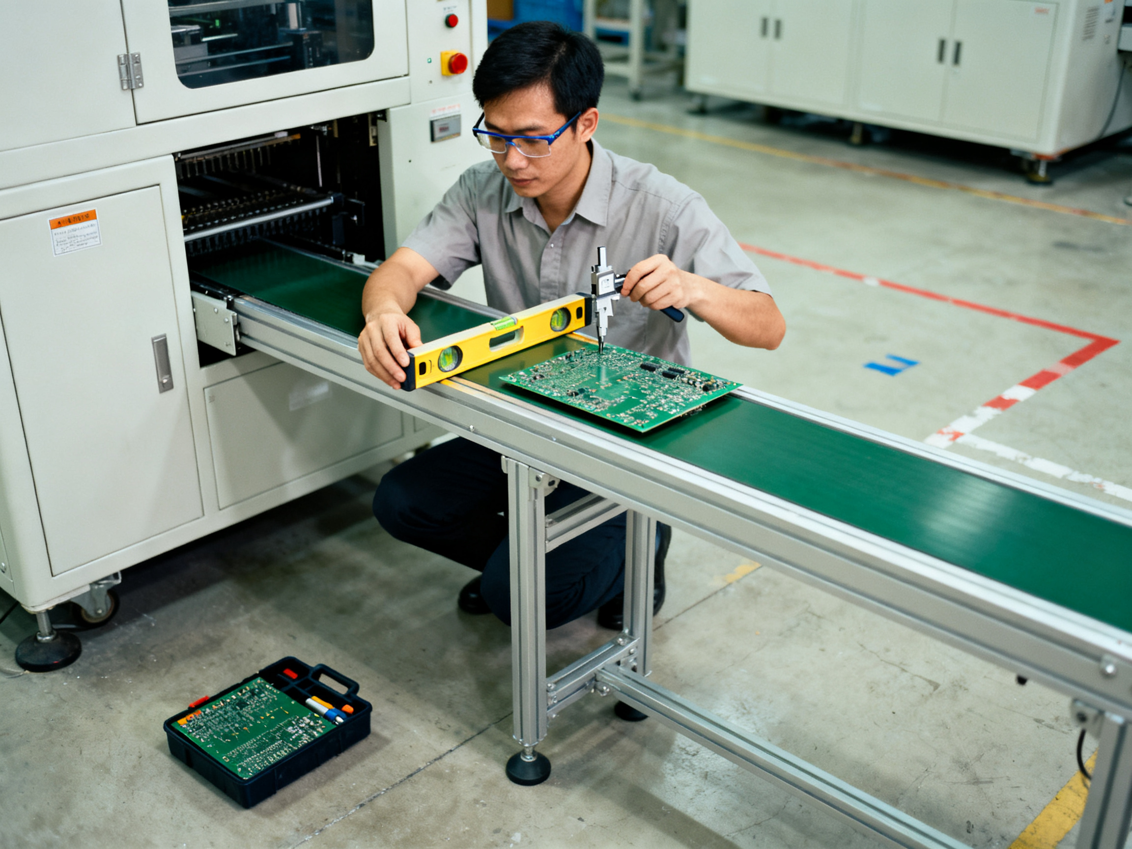
Recommended commissioning sequence
- Inspect the installation. Confirm floor level, service space, power, air quality, guarding, emergency-stop access, and the position of the upstream or downstream equipment.
- Verify the mechanical interface. Check conveyor height, centerline, transfer direction, side-guide position, board support, magazine seating, tray orientation, and available clearances.
- Set the pitch. Configure the pitch from the actual board or tray specification and confirm that the setting is protected against unauthorized changes.
- Check sensors. Simulate missing boards, double boards, skewed panels, magazine-present signals, transfer completion, and jam conditions. Verify that each fault produces the intended alarm and safe response.
- Test the signal handshake. Confirm ready, busy, board-available, fault, and transfer-complete states in both directions. Establish which device is the master and how an interrupted sequence is recovered.
- Run empty tests. Repeatedly cycle the transfer mechanism without boards. Listen for abnormal impact, inspect guide alignment, and verify that the machine returns consistently to its home state.
- Run representative product. Test every active format, including the largest board, most fragile panel, most demanding tray, and product used for the shortest interval between changes.
- Complete the acceptance test. Measure sustainable throughput, record failures and alarms, train operators, verify spare parts, and document the agreed operating settings.
Table 6. Troubleshooting by symptom
| Symptom | Likely cause | Corrective action | Verification |
|—|—|—|—|
| Frequent board miss | Incorrect pitch, sensor alignment, or edge clearance | Recheck the format setting, sensor position, and board support | Run at least 50 consecutive transfers with the affected format |
| Double load | Presence sensor not detecting the second board or detection timing too short | Clean and align sensors; review detection logic and timing | Deliberately attempt a double-board condition and confirm rejection |
| Board enters skewed | Guide-rail mismatch, uneven support, or transfer-speed mismatch | Align guides and support surfaces; synchronize conveyor and transfer motion | Inspect board position across the full conveyor length |
| Magazine will not index | Incorrect pitch, magazine not seated, or index sensor fault | Seat and latch the magazine; confirm pitch; inspect the index sensor | Repeat indexing through the full magazine range |
| Line waits for boards | Buffer empty, upstream signal missing, or intermittent sensor fault | Check buffer contents, handshake states, wiring, and sensor reliability | Trace a complete upstream-to-downstream transfer sequence |
| Machine runs boards together | Pitch set below board length or conveyor spacing too small | Correct the pitch and conveyor spacing | Test transition between the two most similar formats |
| Repeated transfer jam | Misaligned receiver, foreign material, worn transfer surface, or incorrect timing | Isolate the mechanism, remove debris, align the receiver, and inspect wear parts | Perform repeated cycles with production-representative boards |
| Fault after power restoration | Unconfirmed magazine position or incomplete homing sequence | Perform controlled recovery and verify position feedback | Repeat the restart test at least three times |
ROI example and methodology
A loader or unloader can reduce repetitive manual handling, but the business case must include the full operational effect. A simple calculation is:
Net labor saving per shift = avoided handling hours × loaded labor rate − added operator and maintenance cost
For illustration only, assume a fully loaded labor rate of $35 per hour, 7.5 net productive hours per shift, a board value of $12, and a defect rate of 0.5%. If automated handling saves 1.5 operator-hours per shift, the direct labor saving is $157.50 per shift. If handling-related damage affects 20 boards per month at $12 each, the modeled damage exposure is $240 per month before recovery effects.
These figures are placeholders, not a universal business case. Replace the assumed labor rate, loaded hours per shift, board value, defect rate, handling volume, equipment cost, energy cost, maintenance cost, and expected service availability with documented plant data. Include the capital cost, installation, spares, training, and downtime during changeover. The ROI example is valid only if the underlying assumptions are verified for the intended installation.
Final buyer checklist
- [ ] Every board, panel, tray, magazine, and conveyor format is shown on an approved drawing
- [ ] The minimum and maximum dimensions fall within the supplier’s supported range
- [ ] Pitch options are mechanical settings rather than unsupported software assumptions
- [ ] Conveyor height, direction, speed, width, and guide range match the connected equipment
- [ ] Maximum weight and edge-clearance limits exceed the actual production requirement
- [ ] Sustainable throughput is demonstrated with representative products
- [ ] Buffer capacity and operator replenishment time are adequate for the planned shift
- [ ] Ready, busy, board-available, fault, and completion signals are documented
- [ ] The signal master, timeout, retry, and restart behavior are agreed
- [ ] Missing-board, double-board, skew, full-output, and jam conditions are tested
- [ ] Safety guards, interlocks, emergency stops, and applicable current standards are verified
- [ ] ESD requirements are included in the installation and acceptance criteria
- [ ] FAT and SAT criteria are written into the purchase order
- [ ] Operator training, manuals, spare-parts list, warranty, and local service support are defined
- [ ] ROI assumptions are based on documented plant data
- [ ] The author biography and reviewer details are verified before publication
Standards and references
The final compliance checklist must cite the current editions of the applicable machine-safety, electrical, and ESD standards used by the plant and the supplier. Editors should verify the exact editions against current official publications rather than rely on a generic reference.
The following published specification source was used for the equipment-comparison framework and for specification fields that require dated verification:
- PCB Handling Machine Specification Overview, S&M Co. Ltd. — checked November 2026.
Visual placement
Production note: commission original visuals for the full line diagram, loader and unloader sequences, configuration layouts, signal handshake, annotated magazine alignment, and a commissioning video. Each visual should include a takeaway-led caption, descriptive alt text, source or provenance details, and a dated note where specifications are shown.
Author: [Name to be verified]
Author biography: [Biography to be verified]
Technical reviewer: [Named SMT engineer pending verification]
Review status: The takt calculation, failure modes, and safety and ESD checklist remain subject to technical sign-off before publication.