
What Nitrogen Actually Changes in a Reflow Profile
Nitrogen does not lower a component’s peak temperature or replace the solder paste’s thermal requirements. It changes the atmosphere around the board while the solder is molten. By displacing oxygen, nitrogen slows oxidation of the liquid solder, reduces the formation of a stable oxide skin, and helps molten solder wet and flow across the pad before it cools.
That distinction matters because a lead-free profile must do several things at once:
- Heat the solder paste through its melting range.
- Maintain enough time above the melting point for flux to clean the pad and solder to spread.
- Keep the peak temperature below the component and board limits.
- Remove residual solvents without drying the paste before it can wet.
- Cool the assembly in a controlled manner.
The atmosphere cannot compensate for a poor profile. If a board is heated too quickly, held too long, or exceeds safe temperature limits, adding nitrogen will not make that profile suitable. It will, however, often reduce the oxidation-related symptoms that appear when an otherwise reasonable lead-free profile is exposed to ordinary air.
The Main Benefits
Lower oxidation during heating. Nitrogen reduces the oxygen available to react with the solder. This is particularly useful from the point at which the solder begins to flow until it becomes fully solid.
More consistent wetting. When an oxide skin inhibits wetting, the solder forms a high-contact-angle bead instead of spreading across the pad. Improved wetting makes joint fillets more repeatable and can reduce weak or insufficient solder joints.
Less solder-ball generation. Oxidation products and poor wetting can contribute to solder balls around component terminations. A cleaner melt generally reduces this defect mechanism, although print quality, paste condition, thermal profile, and component placement remain critical.
Better surface appearance. Dull, grainy, or rough solder surfaces often indicate oxidation. Nitrogen-reflowed joints are typically smoother and brighter, making visual inspection easier.
Reduced dross and rework. Less oxidation means less material is converted into non-wetting residue. This can reduce maintenance on the oven’s exhaust and dross-management systems and reduce the number of boards requiring touch-up.
Nitrogen should therefore be treated as a process-control tool, not as a universal defect cure. It is most valuable when the oven, board, components, paste, and thermal profile are already well controlled.
Nitrogen Reflow Soldering Process: Step by Step
A reliable nitrogen reflow cycle has six stages. Each stage should be verified using actual product data rather than inferred only from oven settings.
1. Verify the Paste, Board, and Components
Before starting a production trial, confirm that the paste alloy is suitable for the product. The alloy’s liquidus temperature, the component manufacturer’s recommended reflow profile, the board finish, and the stencil design must be compatible. Most modern electronics use SAC305, SAC305 with additions such as silver, or another lead-free alloy, but the correct choice depends on the application and its quality requirements.
Also check:
- Paste storage and temperature records.
- Paste mixing time and the interval between mixing and use.
- Stencil aperture and paste-release performance.
- Component placement force and solderability.
- PCB thermal capacity and layer count.
- Moisture status, where applicable under the relevant handling specification.
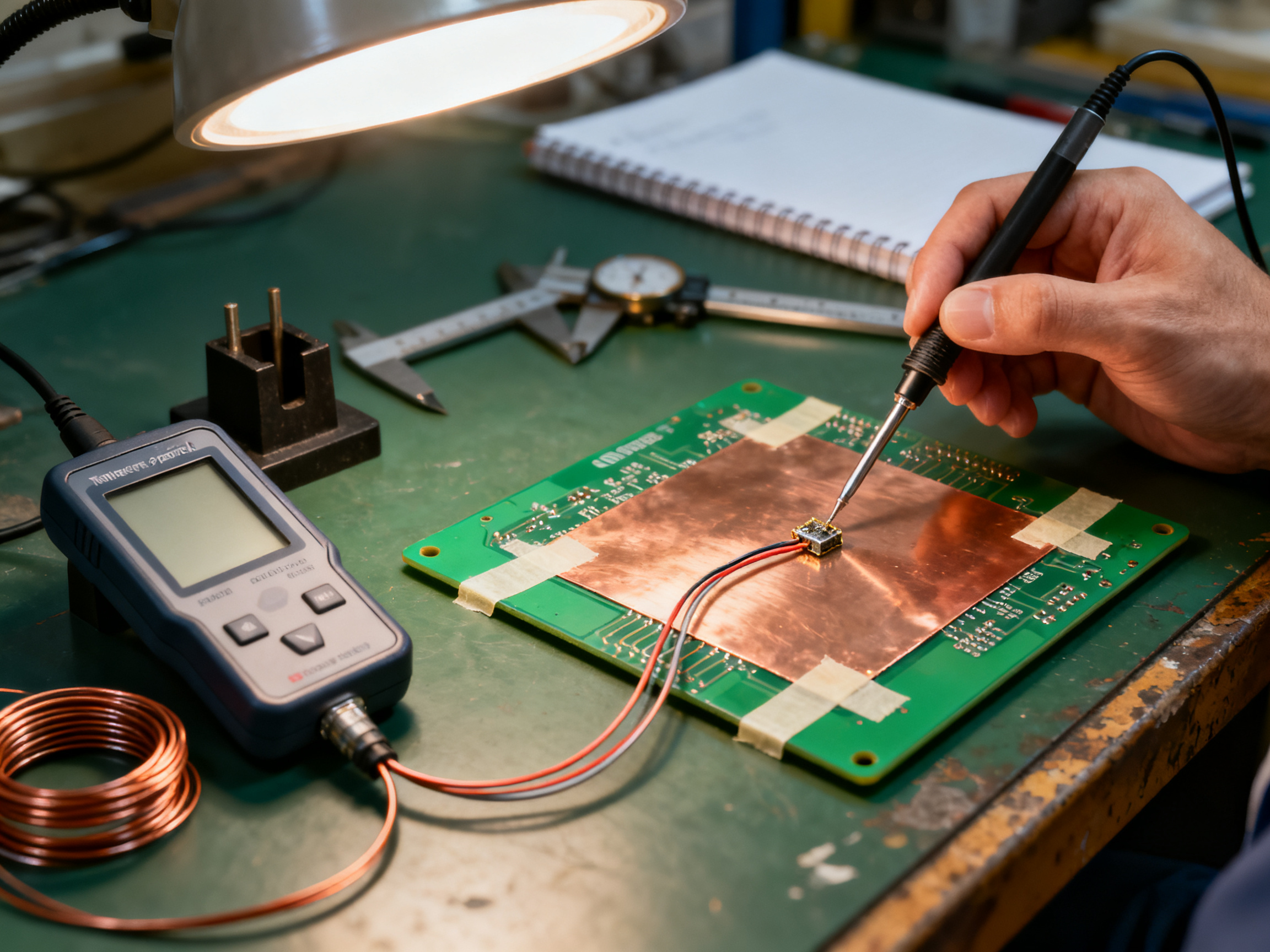
Nitrogen will preserve the condition of good material more effectively than it can rescue contaminated paste or poorly prepared pads.
2. Prepare and Seal the Oven
Check the oven’s seals, nitrogen supply, flow-control equipment, exhaust path, and monitoring instruments before loading production boards. Confirm that the oven is operating within its specified temperature and atmosphere limits.
A practical setup should include:
- A dedicated, suitably rated nitrogen source.
- Regulated delivery pressure and flow control.
- An independent oxygen monitor if the process specification requires atmospheric verification.
- Leakage alarms or low-supply interlocks.
- Temperature profiling instruments suitable for the product and board construction.
- Safe exhaust ventilation and appropriate oxygen-deficiency safeguards.
Do not assume that a sealed oven is automatically full of useful nitrogen. A small air leak can materially change the atmosphere, especially during low-flow or idle periods. The required oxygen concentration must be defined by process validation rather than by a generic industry assumption.
3. Establish the Preheat Zone
The purpose of preheating is to bring the solder paste, PCB, and components to a controlled temperature while removing solvents and preventing thermal shock. Preheat duration and ramp rate depend on board size, copper mass, component mass, paste chemistry, and the oven’s heating method.
During preheat:
- The paste should not dry completely before reaching the reflow zone.
- Solvent evaporation should remain gradual and controlled.
- Component bodies should not be exposed to damaging thermal stress.
- The board should reach the required soak temperature without excessive dwell time.
A nitrogen atmosphere can be used during portions of the cycle, but the benefit is greatest while molten solder is present. Its use earlier in the cycle must still comply with the oven manufacturer’s safety and process instructions.
4. Soak and Flux Activation
In the soak region, the assembly remains near the solder alloy’s melting range for a controlled period. This allows the flux to activate and clean the pad. The soak profile should be sufficient to reach the paste supplier’s intended liquidus condition without unnecessarily extending the cycle.
Watch for condensation, discoloration, premature drying, or signs that the board is taking heat too quickly. Nitrogen may improve environmental consistency, but it does not change the thermal mass of the assembly or create additional process margin by itself.
5. Reflow and Wetting
The reflow region brings the solder to its liquidus temperature and provides the time needed for wetting. The peak temperature, time above liquidus, ramp rate, and total cycle duration must remain within the limits of the paste, board, and component manufacturers.
For lead-free alloys, the liquidus is commonly around 217°C, while a typical peak may fall in the broader 235–250°C region. These figures are not universal targets. A large automotive or telecommunications assembly may require a different profile from a small consumer-electronics board. The component manufacturer’s soldering instructions and the paste supplier’s recommended profile take precedence.
Nitrogen is especially useful in this region because the solder is molten and most exposed to oxidation. The atmosphere should be verified under representative loading conditions, not only with an empty oven.
6. Controlled Cooling
Cooling completes metallurgical formation of the solder joint. Rapid cooling can create thermal stress, while uncontrolled cooling can contribute to distortion or inconsistent joint appearance. The cooling stage should be validated with the actual assembly.
A suitable profile usually defines the cooling ramp from the peak temperature to a target temperature, followed by enough time in the oven to bring the assembly within an acceptable exit condition. If the oven uses forced airflow, confirm that airflow is stable and that the measurement location reflects the assembly rather than a single point in the chamber.
After unloading, allow the assembly to cool naturally where the product specification requires it, then inspect the joints before packing or conformal coating.
Nitrogen Reflow Oven Setup Requirements
A credible nitrogen system should be specified around atmosphere control, thermal performance, safety, and maintainability. At minimum, evaluate the following.
Atmosphere and Gas Management
- Nitrogen purity: Specify the purity appropriate to the process and supplier. Higher purity is not automatically more economical if the oven and process do not require it.
- Oxygen monitoring: Use an instrument with a measurement range appropriate to the specified oxygen limit. Low-range electrochemical sensors, for example, are commonly used to detect trace oxygen, but sensor selection and calibration must match the application.
- Flow control: The system should maintain stable gas delivery through the required cycle stages and compensate for leakage and temperature-related density changes.
- Sealing: Inspect door seals, chamber penetrations, feed openings, and cooling or exhaust interfaces for leakage.
- Supply redundancy: For critical production, consider a backup supply, automatic changeover, or a controlled procedure for safely continuing production.
Thermal Capability
The oven should deliver the required heating and cooling rates for the full range of product loads. Review:
- Heating method and available power.
- Temperature uniformity at operating temperature.
- Recovery time after a board or load change.
- Profile repeatability across chamber positions.
- Thermocouple attachment methods and probe durability.
- Ability to store validated profiles for recurring products.
A multi-zone oven is useful when different products require distinct heating, soak, reflow, and cooling conditions. However, additional zones add complexity only if they improve control for the actual product mix.
Safety and Environmental Controls
Nitrogen is non-flammable, but it can displace oxygen. The installation should therefore include:
- Exhaust ventilation engineered for the gas-flow rate.
- Appropriate room oxygen monitoring where required by the risk assessment.
- Interlocks and alarms for loss of ventilation, excessive gas flow, or other hazardous conditions.
- Clear lockout and tagout procedures.
- Training for operators, maintenance personnel, and emergency responders.
- Compliance with local workplace and electrical requirements.
The oven supplier should provide commissioning records, operating manuals, maintenance schedules, sensor calibration instructions, and emergency procedures.
Process Monitoring
For stable production, record or otherwise control:
- Oven zone temperatures.
- Board and component thermal profiles.
- Nitrogen flow and pressure.
- Oxygen concentration where specified.
- Start and end times for each product run.
- Profile version and any deviations.
Data should be retained according to the company’s quality system. A dashboard that displays only chamber temperature is useful for operators, but it is not a substitute for product-level thermal profiling.
A Practical Validation Plan
Do not convert the production line to nitrogen based on a successful trial of one easy board. Validate the process using representative products, including the highest thermal load, the smallest product, and any board with unusually large copper planes or heavy components.
Stage 1: Establish the Air Baseline
Run representative boards in air using the current thermal profile. Record defects and inspect the same features after each trial:
- Joint wetting and fillet shape.
- Solder balls and paste residue.
- BGA void levels under the applicable acceptance method.
- Through-hole fill and top-side wetting.
- Component discoloration.
- Rework frequency.
- Cycle time and oven energy consumption.
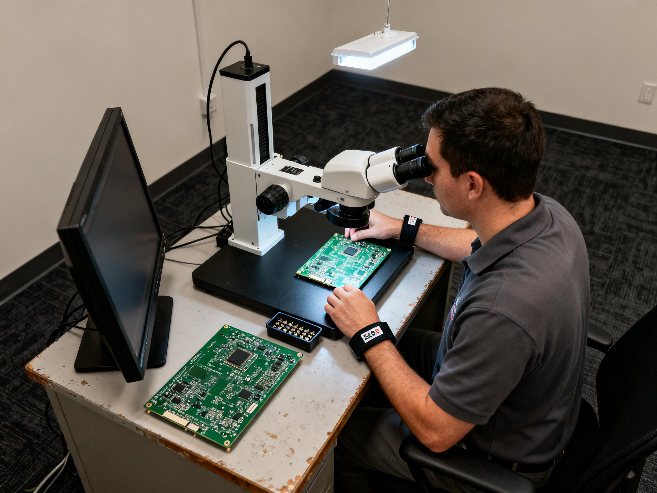
This baseline prevents the team from attributing unrelated process changes to nitrogen.
Stage 2: Qualify the Nitrogen System
Commission the oven, verify seals, calibrate sensors, and confirm flow and atmosphere stability at idle and under load. Test the system after opening the door, changing products, or encountering a supply interruption. The relevant question is not merely whether nitrogen is present, but whether the specified atmosphere is maintained throughout the period when it is needed.
Stage 3: Optimize the Thermal Profile
Use the nitrogen trial to evaluate thermal profiles in a controlled sequence. Start with the existing profile, then adjust only one variable at a time, such as soak time, time above liquidus, peak temperature, or cooling rate. Record both defect performance and process-window performance.
A lower peak temperature may become possible after oxidation is reduced, but that change should never be made solely because joints look better. It must remain compatible with the paste and component requirements and should be validated through repeatability and capability testing.
Stage 4: Run Production Trials
Run enough cycles to include normal production variation. Include multiple loading patterns, planned maintenance interruptions, shift changes, and replenishment of the nitrogen supply. Confirm that operators can repeat the process using the written instructions.
Stage 5: Establish Control Limits
Define alarm and action limits for temperature, oxygen concentration where applicable, flow, pressure, and profile deviation. The control plan should identify who may release a hold, what evidence is required, and how nonconforming boards are segregated.
Troubleshooting Common Nitrogen-Reflow Defects
A defect symptom does not identify its cause by itself. Use the troubleshooting sequence below, but investigate print quality, placement, component condition, thermal history, and paste handling alongside the atmosphere.
| Symptom | Likely contributors | Checks and corrective actions |
|—|—|—|
| Dull, rough, or grainy solder | Oxidation, excessive dwell, inadequate atmosphere control | Verify nitrogen flow and oxygen readings; inspect seals; confirm peak temperature and time above liquidus; check paste age and mixing. |
| Poor wetting or insufficient fill | Oxide or contamination, low peak temperature, short reflow time, pad finish issues | Check the actual product profile; confirm liquidus exposure; inspect pad and paste; verify that the atmosphere is controlled during reflow. |
| Solder balls | Poor paste release, excessive void pressure, placement issues, oxidation | Inspect stencil condition and apertures; review paste printing; check component placement force; confirm the reflow profile. |
| Excessive residue | Flux chemistry, low reflow temperature, extended soak, contamination | Check paste type and storage; review ramp and soak; verify component and board cleanliness. |
| BGA voids | Outgassing, moisture, paste volume, pad design, thermal profile | Review drying and handling requirements; confirm paste-print volume; use X-ray analysis; evaluate soak and peak conditions. |
| Discoloration | Excessive temperature or dwell, component limitations, flux reaction | Compare chamber and board temperatures; review component specifications; shorten exposure only after confirming the required wetting time remains. |
| Inconsistent joints between boards | Profile or atmosphere variation, loading pattern, mixed paste ages | Profile boards at different positions; check recovery time; standardize loading and paste rotation. |
| Joints that wet well in nitrogen but not in air | Expected atmosphere benefit, possible thermal-profile weakness | Compare surface finish and fillet geometry; retain the qualified profile and atmosphere set point as process controls. |
When the Defect Remains After Adding Nitrogen
If defects persist, do not immediately increase gas flow or lower the peak temperature. Work through the evidence in this order:
- Confirm that the board actually experienced the intended thermal profile.
- Confirm that the atmosphere was in specification during the molten phase.
- Verify the paste condition, alloy, and printing quality.
- Review pad finish, board cleanliness, and component solderability.
- Check placement force, tombstoning risk, and component orientation.
- Compare the defective region with known-good locations and production records.
Nitrogen addresses oxidation. It does not correct a misaligned stencil, an exhausted paste, an unsuitable pad finish, or a component that has exceeded its handling life.
The Business Case: Build It From Real Production Data
The financial justification for nitrogen reflow should be calculated from the customer’s actual defect and operating data. A vendor’s generic claim that nitrogen always eliminates solder balls is not sufficient evidence.
Build a baseline for the selected line:
- First-pass yield.
- Defects by type and root cause.
- Number of boards requiring rework.
- Rework labor and material cost.
- Scrap and customer charge-back cost.
- Inspection labor, including X-ray and manual verification.
- Oven maintenance and consumable cost.
- Energy use and nitrogen consumption.
- Cycle time and production throughput.
- Cost of a field failure, warranty claim, or customer disruption.
A simple annual-value model can then compare the current process with the nitrogen process:
Annual benefit = avoided scrap + avoided rework labor and materials + avoided field failures + reduced inspection burden + reduced dross and maintenance cost.
Annual operating cost = nitrogen consumption + added energy + sensor maintenance and calibration + service contracts + operator training + allocated depreciation.
Net annual value = annual benefit − annual operating cost.
Payback period = initial investment ÷ annual net value.
Run the calculation for several scenarios rather than presenting one optimistic forecast. Use conservative values for process improvement and include the cost of maintaining gas infrastructure. If the line produces several product families, model each family separately because nitrogen may provide a large benefit on one thermally demanding assembly and only a modest benefit on another.
Benefits That Are Often Overlooked
In addition to fewer defective joints, a controlled atmosphere may contribute to:
- More stable processes across shifts and seasons.
- Less dependence on operator technique during solder wetting.
- Better repeatability for high-volume or high-reliability products.
- Reduced exposure of hot component bodies to oxidation.
- More consistent evidence during root-cause investigations.
- Lower rework stress on fine-pitch terminations and thermally sensitive parts.
These benefits become more important as product complexity increases. The relevant comparison is not simply the purchase price of the oven. It is the total cost of achieving stable, repeatable quality.
Where the Case May Be Weaker
Nitrogen may not be the best next investment when the dominant problem is caused by printing, placement, paste handling, or component quality. It may also be unattractive for low-volume products with wide process margins, small boards, or applications where the risk assessment shows no meaningful oxidation-related defect mechanism.
Before purchasing, ask the supplier to demonstrate the expected improvement on representative boards and to define the qualification plan. A credible supplier should be comfortable discussing process limits, measurement uncertainty, maintenance, gas consumption, and failure modes rather than promising universal defect elimination.
Questions to Ask an Oven Supplier
A technical evaluation should separate factory capability from marketing claims. Ask for:
- Measured temperature uniformity and repeatability at the intended operating temperature.
- Heating and cooling rates for representative product loads.
- Chamber-volume and gas-consumption calculations based on actual cycles.
- Nitrogen purity requirements and recommended operating range.
- Oxygen-monitor specifications, calibration interval, and alarm configuration.
- Seal design, expected service life, and leak-test procedure.
- Safety interlocks and installation requirements.
- Profile storage, recipe control, and changeover procedures.
- Availability of local service and spare parts.
- Reference installations producing products comparable to yours.
- A documented trial using your own paste, boards, and components.
- Warranty terms covering process-control hardware, sensors, and heating systems.
During the trial, measure more than visual appearance. Record wetting, solder-ball rate, void levels, first-pass yield, rework, cycle time, and profile stability. The best demonstration is not a hand-selected board; it is repeatable improvement across a statistically meaningful production run.
A Controlled Atmosphere Is a Process System
Nitrogen reflow works because it removes one of the most disruptive variables from molten-solder processing: oxidation. The result can be cleaner wetting, fewer solder balls, more consistent joint appearance, and less rework. Those improvements can be commercially significant, particularly for fine-pitch components, BGAs, long-life products, and high-reliability assemblies.
The technology will not deliver those benefits automatically. The atmosphere, thermal profile, paste, stencil, placement process, board finish, and inspection system must work together. The right objective is not maximum nitrogen flow or the lowest possible peak temperature. It is a stable, validated process that repeatedly converts printed solder into compliant joints within safe thermal limits.
Start with a representative baseline, qualify the gas system, profile the product, and compare results using objective defect data. If the baseline shows that oxidation is a meaningful cause of yield loss, a nitrogen process may provide one of the clearest opportunities to improve quality and reduce total cost of ownership on the line.
Why Nitrogen? The Chemistry Behind Inert Atmosphere Reflow
Here is the part most people skip, and it is the part that actually explains why nitrogen reflow soldering is done the way it is.
Molten solder is not inert. When tin reaches its liquidus and sits in contact with oxygen, the tin reacts with O2 and forms a tin oxide skin on the surface of the solder. That skin behaves badly. It raises the effective liquidus temperature of the alloy, and it resists wetting, so molten solder balls up instead of spreading across the pad. You end up with a dull, high-contact-angle joint that looks underfilled even when the paste volume was correct.
The practical effect of oxidation is this: you lose wettability at exactly the moment the joint is being formed. That is why dross, solder balls, and poor fill show up around the same defect mechanism in the same run.
Nitrogen displaces that oxygen at the board surface. Instead of reacting with air, the molten alloy stays chemically clean long enough to wet the pad, the paste chemistry burns off as designed, and the joint forms with a proper fillet.
Air, Nitrogen, or Vacuum?
| Factor | Air convection reflow | Nitrogen reflow | Vacuum reflow |
|—|—|—|—|
| Oxide control | None beyond flux | Strong, actively displaces oxygen | Strong, plus removes vapour and outgassing |
| Cost to run | Lowest | Moderate, driven by gas use and flow rate | Highest, needs sealed chamber and pumps |
| Throughput | Highest | High, small cycle-time penalty | Lower, longer pump-down cycles |
| Flux compatibility | All chemistries | Works with no-clean and water-soluble | Can trap residues, needs planning |
| Typical use | General electronics | Lead-free, fine-pitch, BGA, high-reliability | Specialist or advanced packaging |
Formic acid vapour sits in between on cost, but it introduces acid chemistry into the process and needs careful material and safety planning. Nitrogen wins in most SMT shops because it fits existing flux chemistry and existing conveyor lines without redesigning the product.
Expert Tip: Nitrogen does not clean a dirty pad. It only prevents new oxide from forming while the solder is molten. If your paste is old, your stencil is worn, or your pad finish is poor, more gas will not fix it. Fix the material problems first, then use the atmosphere to protect the joints you are actually trying to make.
That last point is the one worth remembering. Nitrogen is preventative, not corrective. It holds the condition of good material through the hot part of the cycle. It cannot rescue contaminated paste, a misaligned stencil aperture, or a component that has exceeded its storage life.
For lead-free alloys this matters more than it did with SnPb, because lead-free SAC305 has no lead to suppress the oxide reaction the way the old alloys did. That is the core reason lead-free reflow with nitrogen became standard practice, and it is the reason standards bodies such as IPC and JEDEC continue to treat atmosphere control, profile control, and moisture handling under J-STD-020 as separate requirements that a process engineer must satisfy together.
Step-by-Step: How Nitrogen Reflow Soldering Is Done
Here is the actual sequence inside a nitrogen reflow oven, with the numbers we use as starting points on a comparable product mix. Every board follows the same four stages, whether it is a small sensor module or a dense BGA board.
Stage 1: Preheat and Soak
The board starts at room temperature, around 25°C, and comes up gradually to a soak band of roughly 150–200°C. This stage exists for two reasons: get the whole assembly to an even temperature, and drive off solvent without drying the paste out early.
Thermal gradients are the enemy here. A board with a large copper ground plane heats up much faster than a small one with heavy components on the far end. If the ramp is too aggressive, the corners cook while the center is still cold, and you get a profile that looks fine on the profiler chart but produced uneven joints across the panel.
Nitrogen flow is usually ramped in rather than applied at full rate from the first minute. Flowing hard gas through a cold chamber creates draughts across the board, which can disturb wet paste deposits and cool the assembly unevenly. Most lines bring the gas up around preheat or soak and hold it there.
Stage 2: Ramp to Liquidus
The soak ends and the oven ramps toward the reflow zone. For SAC305 the liquidus sits at about 217°C, and a typical peak lands somewhere in the 235–250°C region for lead-free work. The ramp rate is usually controlled to roughly 1–2.5°C per second so the profile lands inside the paste manufacturer’s window.
This is where oxidation normally gets ugly. Between soak and peak, the solder is heating toward liquidus and the flux is burning off its active ingredients. Without control, that is the point where the first oxide skin forms and starts to fight the wetting process. Nitrogen suppresses it, which is exactly why the atmosphere matters most in this stage and the next one.
Stage 3: Time Above Liquidus
Once the alloy passes liquidus, the board sits above 217°C for a controlled window. We typically work with 5 to 60 seconds depending on package density and board thermal mass. This is the shortest and most critical part of the cycle.
While the solder is molten, the actual joint forms. Intermetallic compounds grow at the pad interface, the solder wets the pad and component termination, and the fillet geometry is set. On a BGA or QFN, this is also where an oxide film or trapped void will ruin the joint if it has anywhere to go.
Nitrogen earns its cost here because it keeps the molten surface chemically clean, which preserves flux activity through the wetting window and cuts dross generation. It is not a dramatic visual change during this stage. It shows up later, in X-ray void levels, fillet consistency, and solder-ball counts.
From Our Experience: In the field, most oxygen-related defects we chase back to the oven turn out to be traced to the gas delivery plumbing, not the oven itself. A dried nitrogen line, a dew point that drifted high, or a flow meter reading well off its set point will quietly ruin the atmosphere long before anything shows up on the chamber display. That is why we always measure actual O2 at the board surface rather than at the gas inlet. What enters the line and what reaches the molten solder are two different numbers.
Stage 4: Cooling and Solidification
The final stage brings the assembly down through the solidification range. Cooling rate matters because the joint is still forming as the alloy freezes, and too much shock can lift pads, stress packages, or trap voids. We aim for a controlled cool of no more than about 4°C per second.
Forced-air cooling inside the nitrogen chamber helps here, and the inert gas carries over into the cooling zone rather than being flushed out immediately. That keeps the freshly solidified joints from re-oxidizing before they reach a safe handling temperature. Once the board exits, let it cool naturally where the product specification requires, then inspect before packing or conformal coating.
Typical Profile Parameters
| Parameter | SAC305 | SAC107 | Notes |
|—|—|—|—|
| Liquidus temperature | Approx. 217°C | Approx. 220°C | Set the target from the paste datasheet |
| Soak band | 150–200°C | 150–200°C | Equalization before ramp |
| Soak time | 60–120 seconds | 60–120 seconds | Adjust for board thermal mass |
| Ramp rate to peak | 1–2.5°C/sec | 1–2.5°C/sec | Avoids skinning and dry-out |
| Peak temperature | 235–250°C | 230–245°C | Stay under component limits |
| Time above liquidus | 5–60 seconds | 5–60 seconds | Longer for dense BGA arrays |
| Cooling rate | Up to approx. 4°C/sec | Up to approx. 4°C/sec | Validate with the actual assembly |
These are starting points, not specifications. The paste supplier’s recommended window and the component manufacturer’s soldering instructions always take precedence, and every profile gets confirmed on real product with a profiler before it goes into production control.
For more on how nitrogen reflow oven works in practice, including gas sizing and oxygen level control, see how the S&M Co. Ltd. nitrogen reflow equipment range is set up for lead-free SMT lines.
Nitrogen Reflow Oven Setup Requirements: What Your Line Must Provide
Buying a nitrogen reflow oven is the easy part. Getting it commissioned, fed, vented, and proven on your line is where most projects stall. Here is what your facility and your process actually have to provide in 2026.
Equipment Requirements
| Requirement | Typical specification | Why it matters | Common failure |
|—|—|—|—|
| Sealed convection chamber | Nitrogen-compatible gaskets, sealed feed and exhaust ports | Leakage raises residual O2 and kills the process | Door seals compressed or perished after a few cycles |
| Oxygen sensor | Electrochemical or paramagnetic, range matched to the O2 limit | Confirms the atmosphere at the board surface | Sensor installed at the gas inlet, not at the board |
| Flow control | Closed-loop mass flow control with pressure regulation | Keeps the atmosphere stable as chamber temperature changes | Manual regulator, drift overnight |
| Independent cooling zone | Forced-air cooling with stable airflow, separate from gas purge | Controls solidification rate and joint stress | Cooling shares a plenum with the gas sweep |
| Power and footprint | Check kW rating, supply voltage, floor area, and conveyor height | Fits the line and the utility room | Oven arrives and does not fit the building |
| Conveyor interface | Rail width, pitch, board carriers, upstream paste printer and downstream AOI hand-off | Prevents jams and inspection gaps | Mismatch with the existing conveyor |
Expert Tip: During the factory acceptance test, ask the supplier for live O2 ppm logging, not a single snapshot reading at the chamber wall. Then validate the peak and ramp profile with your own profiler instead of trusting the oven’s own chart. An oven can pass every number on the factory floor and still miss your board because your product has different copper mass and component loading.
Facility and Utility Requirements
Plan the layout before the delivery date, because the gas infrastructure is the long pole.
A workable arrangement puts the bulk liquid nitrogen tank or on-site generator outside the production area, feeding a manifold that runs to the oven’s gas inlet, with the exhaust routed separately to a vent:
N2 tank / generator -> dryer + filter -> regulator + flow meter -> oven inlet
Oven chamber -> exhaust damper -> building vent (outside make-up air)
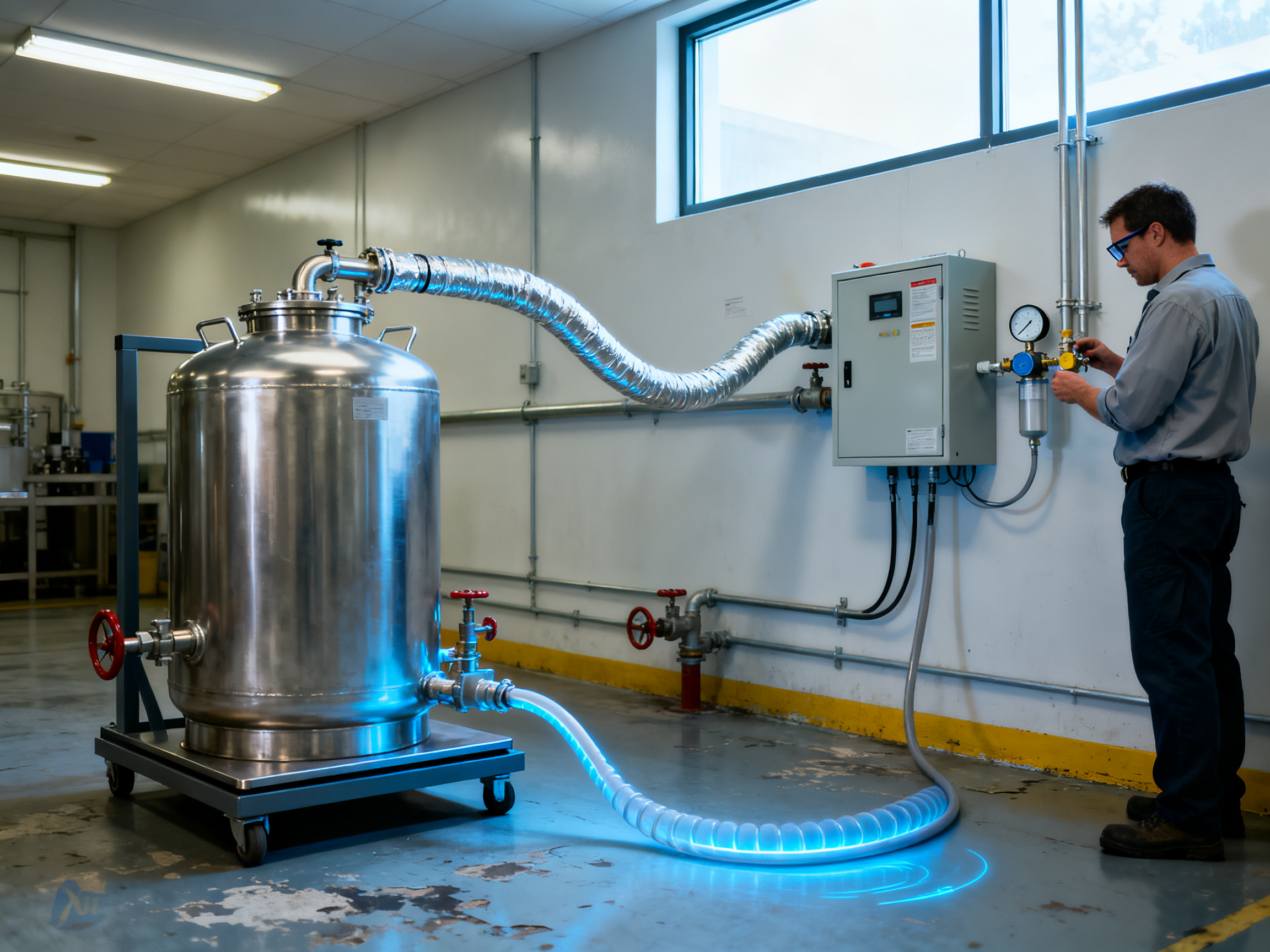
Also confirm:
- Bulk nitrogen or generator. For continuous running, liquid bulk with automatic changeover is more stable than swapping cylinders.
- Facility nitrogen supply. Specify required delivery pressure and dew point, and insist the gas arrives dry.
- Compressed air. Needed for cooling, purge, and instrument operation; check whether it is clean and dry enough for the sensor.
- Floor load and footprint. Includes the tank, the gas cabinet, and service access around the oven.
- Exhaust and ventilation. Vent sizing must match gas flow rate, and make-up air has to be accounted for.
- Ambient temperature and humidity. Chamber performance and sensor readings shift if the room swings widely.
Process Setup
Once the hardware is in place, the work shifts to the process.
Confirm paste and component compatibility before you build recipes, including alloy choice and the paste supplier’s profile window. Then map the hand-off points: stencil printing, placement, oven, and AOI or ICT inspection. Check that a board exits the oven in a state the inspection equipment can handle.
Recipe creation is a profiler job. Capture a real profile on a real board for every product family, store it under version control, and re-profile after any product, stencil, or paste change. Then train the operators. An untrained crew running a qualified recipe badly will still produce defects, and you will spend the first month debugging the oven instead of the process.
Finally, put a maintenance schedule in place from day one: sensor calibration intervals, seal inspection, filter changes, and a documented gas-change procedure.
Compliance and Documentation
For audit-ready operations, log O2 readings, profile data, and profile version for each production run. Tie the records into your quality system so the trail survives a customer audit.
RoHS and REACH material compliance should be documented for the equipment itself, including the sensors, gaskets, and any cleaning agents used on the chamber. For military and aerospace work, the customer may require qualification evidence that goes beyond a standard acceptance test, such as recorded commissioning data, stability runs, and process qualification on the actual assembly.
Ask for commissioning records, operating manuals, calibration certificates, and emergency procedures as part of the handover package. A line is not ready until the documentation and the trained people are in place.
For a reference on how these systems are configured for lead-free SMT lines, take a look at the S&M Co. Ltd. nitrogen reflow equipment range.
Benefits, ROI, and Production Metrics for Nitrogen Reflow
Here is where the conversation usually goes sideways. A supplier promises “zero defects” and the buyer starts doing the math on an oven price. Wrong end of the telescope. The real return sits in first-pass yield, rework hours, and scrap, and you can only value it once you have a defensible baseline.
Quality Gains You Can Measure
On BGA, QFN, and fine-pitch parts, the gains show up in four places: lower void levels under the package, fewer solder-melt insufficiencies, less dross inside the chamber, and a cleaner joint appearance that makes AOI judgment easier. First-pass yield usually moves a little, maybe half a point to two points. Rework rate moves more, because the joints that used to need touch-up now pass inspection.
Operational Gains Worth Counting
- Less rework and less scrap, both of which carry hidden labor cost.
- Longer paste print-to-reflow shelf life, since the paste spends less time degrading in a hot, oxygen-rich chamber.
- Fewer changeovers spent hand-cleaning oxidized oven interiors.
- Better repeatability across multi-zone recipes, which matters on high-mix lines running 30 or 40 part numbers a shift.
- Support for both high-volume consumer work and long-life industrial programs.
A Simple Payback Model
Below is an illustrative scenario for a line running 500,000 boards per month. It is a model, not a promise. Substitute your own numbers before you commit to anything.
| Metric (monthly, 500k boards) | Air convection | Nitrogen reflow |
|—|—|—|
| Assumed defect rate | 1.2% (6,000 boards) | 0.5% (2,500 boards) |
| Scrap (30% of defects at $12/board) | $21,600 | $9,000 |
| Rework labor (4,200 boards at 6 min, $45/hr) | $18,900 | $7,875 |
| Flux, paste, cleaning and dross waste | $8,000 | $6,500 |
| Gross monthly benefit | $48,500 | $23,375 |
| Nitrogen, energy, calibration, service | n/a | about $5,500 |
| Net monthly gain | baseline | about $17,600 |
At roughly $210,000 for the oven, installation, gas infrastructure, and commissioning, that example pays back inside a year. Run the model at three levels: conservative, expected, and optimistic. If the conservative case still clears 18 months, the investment stands on its own.
Where Payback Is Fastest
BGA-dense electronics, automotive modules with long warranty exposure, and military or aerospace assemblies where a single escaped defect can trigger a field action. Low-volume, small-board work with wide process margins is usually the weakest case.
Pro Insight: Build the ROI model around yield and scrap first, and labor second. Labor savings alone will make a weak case look fine; yield delta is the number that survives scrutiny from a finance team. And model each product family separately, because the same oven can show a 1.8% defect improvement on one board and nearly nothing on another. Telling a customer one percentage for a mixed line is the fastest way to lose credibility.
Before and After, at a Glance
First-pass yield, illustrative 500k boards/month line

Air convection   98.8% |█████████████████████          |
Nitrogen reflow 99.5% |███████████████████████        |
                 0%        50%       100%
One honest caveat: results depend heavily on paste chemistry, stencil design, and board layout. A poorly designed stencil will still produce solder balls in pure nitrogen. See the S&M Co. Ltd. nitrogen reflow equipment range for how the gas and thermal systems are packaged for lead-free SMT lines in 2026.
Common Defects and How to Troubleshoot Nitrogen Reflow
Knowing how nitrogen reflow process works is one thing. Knowing why a board still failed after a qualified nitrogen profile is another. The key mindset: a defect symptom rarely identifies its own cause. Most failures fall into one of three buckets, and they can overlap.
- Process causes: paste printing, stencil condition, placement, thermal profile.
- Atmosphere causes: leaks, weak purge, high dew point, sensor placement errors.
- Component causes: moisture handling lapses, oxidized terminations, damaged packages.
Defect Catalogue
| Defect | What you see | Likely root cause | Corrective action |
|—|—|—|—|
| Cold joint | Dull, gritty, non-reflowed appearance on a few joints | Insufficient heat at that location, cold board edge, component shadowing | Profile the actual board, check soak and ramp at that position |
| Insufficient solder melt | Joint fills but leaves a visible line at the pad edge, especially on large pads | Peak temperature or time above liquidus too low | Raise peak within component limits, extend time above liquidus |
| Non-wetting | High contact-angle bead, solder pulls back from the pad | Oxide or contaminated pad, bad surface finish, poor stencil | Check pad finish and paste condition before touching the gas system |
| BGA voids | X-ray shows hollows under the package, head-in-pillower shape | Moisture, outgassing, too-short soak, paste volume | Review drying, confirm soak, measure paste volume, run SAM analysis |
| Bridging | Solder connects adjacent pads | Stencil aperture too large, paste slump, low peak | Inspect stencil apertures, check paste thixotropy |
| Tombstoning | One end of a chip component lifted | Uneven heating, placement force, insufficient paste | Check placement force, balance the soak profile |
| Pad lifting | Pad peeled from the board | Thermal shock, flex during cool, weak pad adhesion | Slow the cooling ramp, check board construction |
| Excessive intermetallics | Brittle-looking joint, dull matte surface on cool-down | Long dwell at temperature, repeated reflow | Reduce total time above liquidus, limit reflow passes |
Decision Tree for a Failed Board
Board failed inspection
  |
  +-- Is the O2 reading at the board inside the set point?
  |     NO -> fix seals, dryer, flow. Re-test before anything else.
  |     YES -> continue
  |
  +-- Does a profiler run match the qualified recipe?
  |     NO -> correct the profile. Atmosphere cannot fix heat.
  |     YES -> continue
  |
  +-- Is the defect on every board or only some positions?
  |     POSITION-SPECIFIC -> profile repeatability, loading, conveyor
  |     ALL BOARDS -> paste, stencil, components, chemistry
  |
  +-- Check AOI and X-ray data for pattern clustering
Run this order every time: O2 at the board, then the actual profile with a profiler, then gas purity and dryer dew point, then conveyor speed and zone setpoints, then AOI and X-ray data. If you adjust the peak temperature before confirming the atmosphere, you are troubleshooting blind.
Expert Tip: Read O2 at the board surface, not at the gas inlet. Those are two different numbers, and the gap between them is where most “nitrogen was on but defects happened” cases are found.
For lead-free reflow with nitrogen, X-ray or SAM inspection is the only honest way to confirm void levels; visual inspection cannot see inside a BGA. Pull good and failed units and compare them side by side.
More on process setup and gas sizing for lead-free lines in the S&M Co. Ltd. nitrogen reflow equipment range.
Integrating Nitrogen Reflow Into an Existing SMT Line
Most factories adding nitrogen do not build a new line. They take the line they already have and make one section work harder. That changes the whole question, because the real decision is no longer “should we buy a nitrogen oven” but “where does it fit, and do we retrofit or replace?”
Where It Goes and How It Talks to the Line
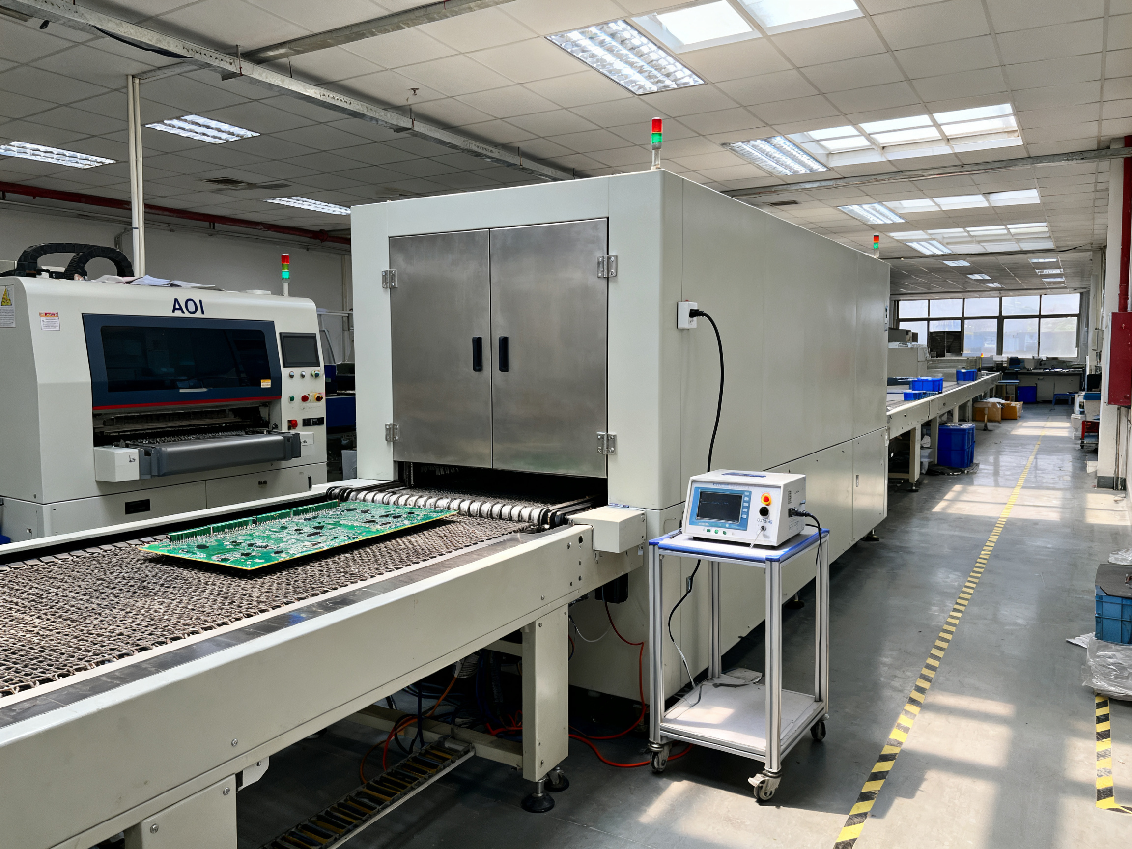
Nitrogen reflow sits in the same slot as a conventional reflow oven: after the mounter, before inspection. The board arrives with components placed and solder paste printed, leaves the oven with formed joints, then goes to AOI, ICT, or whatever downstream test the customer requires.
The integration work is mostly about handshakes. Conveyors, the SPI, the mounter, the oven, and AOI all need to agree on three things: board present, board transferred, board departed. Most shops run this through standard line protocols and SECS/GEM or vendor-specific equipment handshake signals. The oven has to signal “ready to accept” before the upstream machine releases a board, and it has to confirm “board cleared” before the conveyor advances to the next station. Get that wrong and you get a line that stops every third cycle for no obvious reason.
Two details bite people. First, conveyor direction and rail width must match the existing line, or you are rebuilding the transport under a different budget. Second, if the line uses board carriers or a specific pitch, the oven must accept them. Check the physical interface before the electrical one, because it is the cheaper mistake.
Printer  ->  SPI  ->  Mounter  ->  Nitrogen Reflow  ->  AOI  ->  ICT
   |         |         |              |                     |      |
   +-- paste data ----->+              |                     |      |
   +-- placement data -------------------->                   |      |
   +-- board present ------>+             |                     |      |
   +-- recipe version ------+-------------+                     |      |
   +-- O2 / profile logs ------------------------------->     |      |
   +-- defect and X-ray results <------------------------------------+
Read that diagram as two flows. Product flows left to right. Data flows both ways. Recipe versions and profile logs travel with the board so that when a defect shows up at AOI, the team can pull the exact O2 reading and thermal profile for that run instead of guessing.
Retrofit or Replace
A retrofit means keeping the legacy oven for its existing recipes and adding a nitrogen zone for the products that need it. A replacement means swapping the oven outright.
| Criterion | Retrofit to a nitrogen zone | Replace the oven |
|—|—|—|
| Capital cost | Lower, but adds gas infrastructure and interface work | Higher, one project, one acceptance test |
| Downtime | Shorter, the legacy oven keeps running | Longer, a full line stop |
| Capacity | Peaks at the combined limit of both ovens | Clean, single throughput number |
| Recipe complexity | Two ovens to load, train, and maintain | One recipe system |
| Future-proofing | Limited if the legacy oven is near end of life | Better if the new oven supports wider package and board mix |
| Best fit | Mixed lines with both easy and hard products | Lines where the old oven is already a constraint |
The breakeven logic is straightforward. Retrofit wins when the legacy oven still has life and the products needing nitrogen are a minority, say 20 to 40 percent of volume. Replace wins when the old oven is the bottleneck, when it cannot be profiled reliably, or when the nitrogen products are most of the schedule.
Plan downtime properly, because this is where projects slip. A retrofit that requires two days of gas trenching, a structural check on the oven frame, and a weekend line stop is a three-week schedule. Put the utility work in front of the equipment delivery, not after it.
People, Recipes, and the Audit Trail
The operator’s job changes when the oven gains an atmosphere parameter. Recipe management becomes the thing that keeps the process honest.
Store one recipe per product, tied to a version number. Lock the critical parameters, so a peak temperature or O2 set point cannot be changed on the fly without a record. When a product, stencil, or paste supplier changes, re-profile and re-approve the recipe before it goes back into production.
Run SPC on two things: defect rates by type, and O2 readings by run. The first tells you if the process is drifting. The second tells you if the gas system is drifting. Looking at them separately saves a lot of argument in the middle of a shift.
For aerospace and military customers, the documentation expectations go further. Expect to show profile qualification records, gas purity and dew-point certificates, sensor calibration history, and change-control records for every recipe revision. Assume the audit will ask which operator ran which recipe on which date, and build the log so you can answer it in under a minute.
Expert Tip: Plan the gas infrastructure and the utility work before the oven order is confirmed, not after. The chamber is the easy purchase. The trenching, the vent path, and the room monitoring usually decide the schedule.
Done well, the integration changes the line in ways the spreadsheet never showed. Reflow stops being the step that eats the most rework, and the nitrogen oven stops being a separate island with its own manual workarounds. It becomes one qualified section of a line that can actually hold a specification.
From Our Experience: Retrofitting a nitrogen zone into a legacy line is mostly a question of what is already behind the oven. On older cells the exhaust duct is the surprise. If the existing duct was sized for a low-flow air oven, nitrogen flow at production rate will not vent properly, and the fix is ductwork, not a different oven. We always walk the facility route with the installer before the equipment is crated.
Future Trends: Nitrogen Reflow in 2026 and Beyond
Nitrogen reflow is not a finished technology. It is moving in the same direction as everything else on the SMT floor: more measurement, more automation, and less waste.
Here is where the direction of travel looks in 2026:
2026                     Near-term outlook              Beyond
-------------------------------------------------------------------------
O2 ppm logged by default  ->  telemetry into MES           ->  closed-loop
                                                               recipe trim
Sensor checks scheduled   ->  predictive sensor drift      ->  auto-calibration
Multi-zone air + N2       ->  hybrid air/nitrogen zoning  ->  vacuum-assisted
                                                             nitrogen reflow
Manual O2 readings        ->  live board-level O2         ->  per-board gas
                                                               traceability
0.4mm and finer packages  ->  ultra-fine-pitch BGA ramps   ->  lower-temp
                                                             and evaporative
                                                             solders
The shifts worth tracking
Industry 4.0 integration. Real-time oxygen and profile telemetry into the MES is becoming the default request, not the premium feature. Recipe versions travel with the board, and heater zone condition and sensor drift get watched on a curve rather than discovered during an audit.
Harder packages. Fine-pitch and ultra-fine-pitch BGA work keeps the void question central, and advanced memory packaging pushes it further. Evaporative and lower-temperature solders are pushing down peak temperatures, which makes atmosphere control more delicate, not less.
Hybrid and vacuum-assisted systems. Air zones for easy boards, nitrogen zones for the hard ones, and vacuum-assisted nitrogen reflow where void reduction matters more than throughput.
Environmental pressure. Nitrogen consumption per board is becoming a reported number. Leaner flow designs, better sealing, and heat recovery all feed into it.
Expert Tip: In any 2026 oven quotation, ask for live O2 ppm logging during factory acceptance, MES data export in an open format, sensor drift trending and calibration intervals, a stated nitrogen consumption figure at your cycle, and vacuum or hybrid zoning as a documented option. If the quotation cannot answer those in writing, the supplier has not built for the next five years.
The core process stays the same. Displace the oxygen, hold the temperature where the paste supplier wants it, and let the alloy wet while it is clean. Everything new is about measuring that better.
For how these systems are packaged for lead-free SMT lines today, see the S&M Co. Ltd. nitrogen reflow equipment range.
Conclusion: A Practical Framework for Nitrogen Reflow Adoption
Here is the whole process in one line: preheat and soak, ramp to liquidus, time above liquidus, and controlled cooling, with nitrogen suppressing oxidation throughout the hot zone. That is how nitrogen reflow soldering is done, and that is also where the atmosphere helps most.
| Stage | What happens | Why nitrogen matters |
|—|—|—|
| Preheat and soak | Even heating and gradual solvent removal | Protects already-clean surfaces and limits early oxide formation |
| Ramp to liquidus | Alloy approaches its melting point and flux burns off | The first oxide skin forms here without atmospheric control |
| Time above liquidus | The joint forms, while wetting and fillet geometry are set | Provides the greatest benefit by keeping molten solder chemically clean |
| Controlled cooling | The alloy solidifies and joint stress is set | Prevents re-oxidation before the assembly reaches a safe handling temperature |
The deciding variables are paste chemistry, profile control, and gas purity with correct instrumentation. Nitrogen alone will not rescue a bad print or a worn stencil, so sequence the fixes in the right order: material and process first, atmosphere second.
Next steps. Run a controlled A/B trial on the same product mix, comparing air with nitrogen, and measure first-pass yield, a defect Pareto, and consumable cost. Then build the capital case using your own numbers.
Five-item buyer checklist for any 2026 quotation:
- Live O₂ ppm logging during factory acceptance testing.
- Measured temperature uniformity and repeatability at the intended operating temperature.
- Nitrogen consumption at the actual production cycle time.
- Sensor specifications, calibration intervals, and alarm setpoints.
- Open-format MES data export, local service, and spare-parts support.
If you want a written specification for your own product mix, request an oven specification sheet and an on-site process consultation from the S&M Co. Ltd. nitrogen reflow equipment range.