
Publication Information
This article was published on 22 October 2026 and was last updated on 22 October 2026. Its estimated reading time is 15 minutes.## Introduction: Why the Reflow Profile Determines Soldering Quality
Here is the part of SMT that quietly decides your yield. Not the placement machine. Not the printer. The reflow oven and the profile you load into it.
Get it wrong and you get voids inside a BGA, bridging between 0.5 mm pads, a cold joint that passes inspection but fails in the field. Get it right and the same line runs clean at full speed.
But here’s the trap. Most buyers shop by zone count and peak temperature on a spec sheet, then discover at qualification that the board never reaches liquidus on the far edge, or that the oven cooks the biggest components while the small ones sit cold. Zone count does not tell you how a real board heats. Only a profile does.
The IPC-7530 temperature profiling standard makes this clear: each fully populated assembly gets its own temperature versus time plot, measured with thermocouples on the board, not on the oven air.
Over the next 15 minutes, I will walk through choosing an SMT reflow oven, how to calculate reflow oven cycle time, how to set a reflow oven profile step by step, and how to troubleshoot when defects show up. Whether you are qualifying new equipment or fixing an unstable line, this should get you there.
[Visual: annotated PCB defect strip showing bridging, cold joints, QFN voiding, and head-in-pillow]
This article is reviewed by our SMT process engineering team. Author and reviewer details are published here once independently verified, in line with Google’s people-first content guidance.## About the Author
This article is written by [Author Name], [verified title or role], who works with [verified SMT, reflow soldering, electronics manufacturing, or production-line specialty]. [He/She/They] has [verified achievement, certification, project type, or number of years relevant to reflow oven selection and thermal profiling].
We edit this page so every claim about equipment, profiles, and defect causes can be traced to a standard, a manufacturer data sheet, or a documented production result. Where we have run the numbers ourselves, we say so plainly. Where the honest answer is that no universal benchmark exists, we say that too.
Author credentials and reviewer details are published here once they have been independently verified, in line with Google’s people-first content guidance. If you spot something here that we cannot back up, tell us and we will fix it or pull it.
Note for the editor: the bracketed fields above are deliberate placeholders. Please supply a real name, role, and one verifiable credential before publication, and confirm whether a named technical reviewer should be added to the byline.## 1. What Reflow Soldering Is and How a Reflow Oven Works
Soldering an SMT board is not a heat job. It is a controlled timeline.
The board starts life as a bare PCB with copper pads, tracks, and solder mask. A stencil sits over it, and a paste printer pushes solder paste through the stencil apertures so each pad gets a small mound of flux and metal powder. Then the pick-and-place machine sets each component into its paste. Do it wrong here and no oven can save the assembly.
At that point the board looks messy. Chips are floating in grey paste, and nobody knows if the solder will bond. The reflow oven is what turns that into a finished joint.
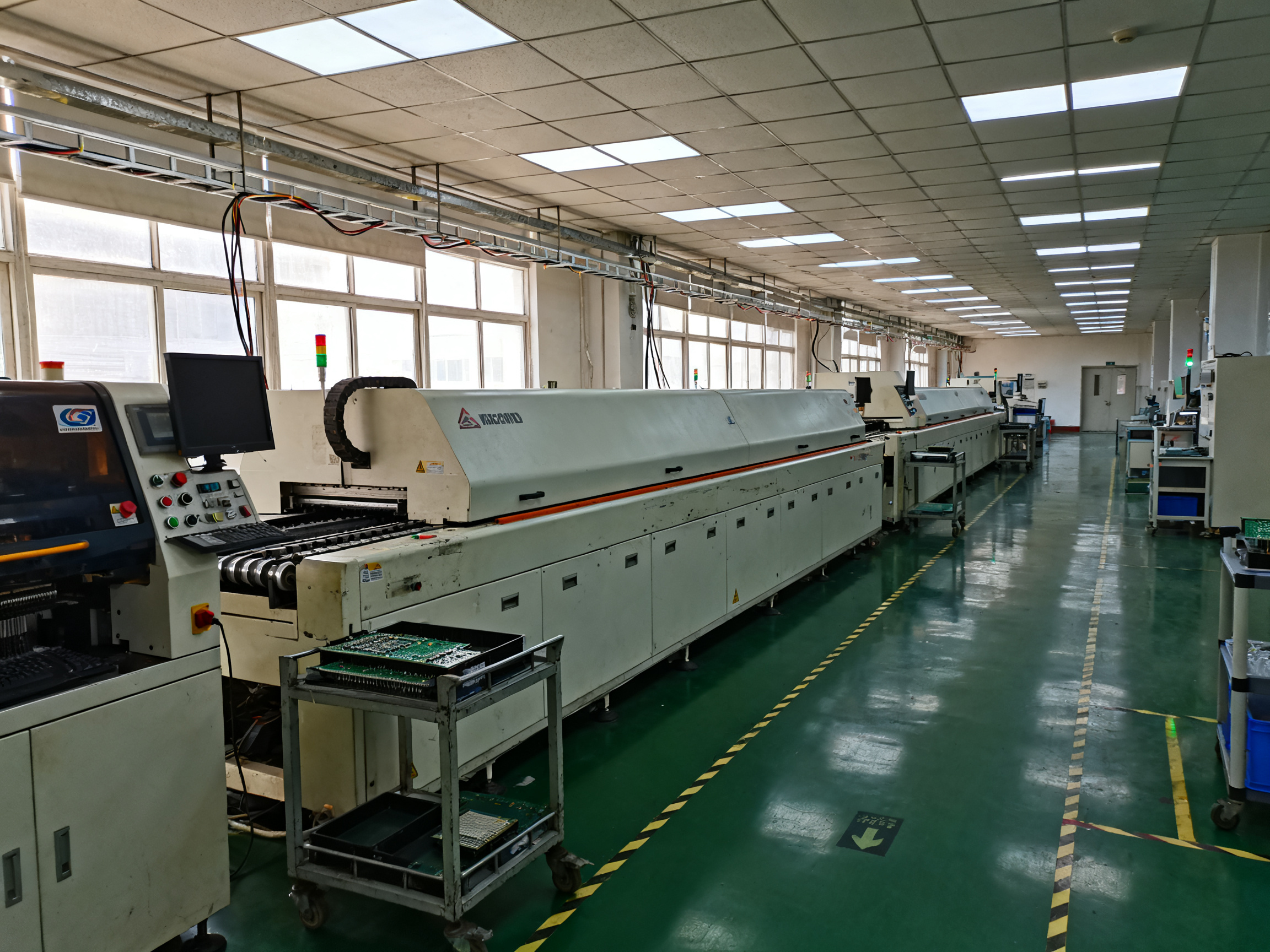
The five stages inside the oven
Here is what happens inside the oven, stage by stage:
- Preheat and ramp. The board comes up to temperature slowly, so flux activates, moisture can escape, and thermal shock stays away from fragile packages. This zone is where most warpage starts if you rush it.
- Soak or dwell. The board sits in a controlled temperature band, usually somewhere around 150 to 200 °C, while the flux finishes its chemistry and the solder particles melt into a liquid. Solder does not melt yet. The flux does.
- Ramp to peak. Temperature climbs past the alloy liquidus, around 217 °C for SAC305. The solder melts, wets the pad and the component terminal, and forms the intermetallic bond.
- Time above liquidus. The board dwells in the molten state long enough for the joint to finish wetting and for voids to float and escape.
- Cool and solidify. Cooling is deliberately controlled, because fast cooling grabs the joint unevenly and pulls on large packages.
Then the board exits, gets inspected, and goes to the next station.
What is reflow soldering used for?
Plenty. Reflow soldering is the standard way to attach surface-mount components, and it covers a wide spread of product types:
- Consumer electronics and smartphones, where boards are dense and mostly BGA and QFN.
- Semiconductor packaging, where fine-pitch leaded devices and flip chips need tight thermal control.
- Automotive, aerospace, and military electronics, where boards use larger packages, heavier ground planes, and often mixed leaded and lead-free assemblies.
What reflow soldering is not good for is through-hole work. That is wave soldering or selective soldering territory. And a hot plate is not a reflow oven, even though it can do a small board in a pinch.
How the machine does it
Forced convection is still the dominant industrial method in 2026. A fan moves heated air across the board inside a series of insulated zones. Each zone has its own heater, blower, and temperature control. The board rides through on a conveyor at a set speed, so each zone applies its temperature for a fixed slice of time.
That last part matters more than buyers expect. Zone count alone tells you almost nothing about uniformity. A 10-zone oven can cook a heavy board at one end and leave it cold at the other if the airflow and airflow balance are poor.
Other parts of the oven matter too:
- Conveyor and rails for speed accuracy, rail parallelism, and support for heavy or warpable panels.
- Exhaust and flux management, because flux residue and outgassing affect cleanliness and airflow balance over time.
- Closed-loop controls with recipe storage, alarms, and traceability of what ran on which board.
Nitrogen reflow soldering is an option worth knowing about. Running a nitrogen atmosphere limits oxidation of the molten solder and often improves wetting on SAC alloys. But nitrogen does not automatically fix voiding, and there is no universal oxygen target that fits every line. Site-specific targets should come from controlled air-versus-nitrogen trials on your own boards.
Expert Tip: When you ask a supplier how well an oven heats, ignore empty-oven temperature-uniformity claims. Ask for a profile on a fully populated, high-thermal-mass board with the thermocouples placed on a large ground plane and at the far end of the board. That is the only number that predicts what your product will see.
Where standards come in
Most of the vocabulary above maps to a published document. IPC-A-610 covers the acceptability of finished electronic assemblies, while IPC-7801 covers reflow oven process control, including baseline verification, periodic checks, calibration, and maintenance. Component handling sits in separate JEDEC documents such as J-STD-020 and J-STD-033.
One important caveat: there is no universal lead-free profile that applies to every paste and every assembly. A SAC305 paste might specify a peak around 230 to 245 °C with roughly 45 ± 15 seconds above liquidus, but that number belongs to that paste’s data sheet, not to the industry as a whole.
[Visual: labeled process-flow diagram from stencil printing to placement to reflow to AOI/X-ray inspection]
[Visual: cutaway illustration of a multi-zone forced-convection oven showing heating zones, blower, conveyor rail, and cooling section]
Next up, we get into the numbers that actually drive your buying decision: zone count, heated length, conveyor speed, and how to calculate reflow oven cycle time.## 3. The Numbers: Heated Length, Conveyor Speed, and Cycle Time
Once you know how many zones you need, it is time to calculate the physical oven dimensions and conveyor settings. These numbers determine whether the machine can meet your throughput without sacrificing the solder profile.
Heated length: use cycle time, not a rule of thumb
The heated length is the distance over which the conveyor passes a board through the oven’s controlled zones. A longer heated length gives the board more time to ramp, soak, reflow, and cool, but it does not automatically mean better performance.
Use this relationship:
Heated length = conveyor speed × cycle time
Conveyor speed is commonly expressed in centimeters per minute, while cycle time is measured in minutes. For example, a conveyor speed of 100 cm/min and a cycle time of 8 minutes require an 800 mm heated length.
Cycle time includes every stage of the thermal process:
- Ramp-up from ambient temperature to the soak or preheat target
- Soak or dwell at temperature to activate the flux and equalize the assembly
- Time above liquidus for the specified reflow period
- Controlled cooling to the required exit temperature
You will notice that some ovens assign different physical lengths to heating and cooling sections. Some also include entry and exit zones that are not thermostatically controlled. Ask the supplier for the usable heated length and the distance from the board’s reference point to the end of the controlled profile—not merely the overall chamber dimensions.
Conveyors run at different speeds for different reasons
A reflow oven may use one conveyor motor and one selected speed, while a more sophisticated machine may provide independent control of the heating and cooling conveyors. The important specification is the range of conveyor speeds available under load and the repeatability of the selected setting.
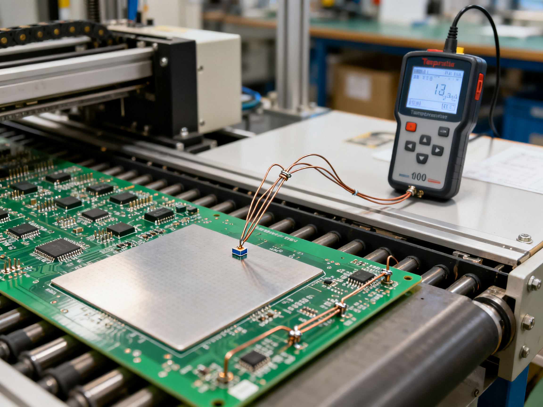
Check the following:
- Minimum and maximum conveyor speed
- Speed accuracy across the full range
- Speed stability after temperature changes
- Performance at the maximum rated board load
- Whether speed can be stored with each recipe
A display showing a precise speed does not guarantee that the conveyor maintains that speed under load. A heavily loaded belt can stretch, slip, or vary if the drive system is undersized. Include a loaded conveyor-speed test in the factory acceptance protocol.
Calculate cycle time from the process profile
A practical way to calculate cycle time is to add the required duration of each profile segment:
Cycle time = ramp time + soak time + time above liquidus + cooling time
Suppose a lead-free paste specifies:
| Segment | Target |
|—|—|
| Ramp-up | 1.0 to 2.0 °C/sec |
| Soak | 150 to 180 °C for 60 to 90 seconds |
| Time above liquidus | 217 °C for 45 to 60 seconds |
| Cooling | To below 150 °C within 120 seconds |
For an initial engineering estimate, add the longest credible duration in each segment:
- Ramp: 120 seconds
- Soak: 90 seconds
- Above liquidus: 60 seconds
- Cooling: 120 seconds
- Total cycle time: 390 seconds, or 6.5 minutes
At 100 cm/min, the minimum heated length for that profile would be:
100 cm/min × 6.5 min = 650 cm, or 6,500 mm
That is a useful screening calculation, but it is not a final specification. The temperature-versus-time curve must be verified on the actual production board. Large ground planes, exposed pads, dense BGAs, and heavy panel fixtures can lag the chamber air temperature substantially.
Work backward from throughput
Throughput requirements should drive the conveyor calculation rather than the other way around. Begin with the required board pitch, which is the distance from the start of one board to the start of the next:
Boards per hour = conveyor speed in cm/min × 60 ÷ board pitch in cm
For example, a line running 100 cm/min with a 10 cm board pitch processes 600 boards per hour:
100 × 60 ÷ 10 = 600 boards/hour
Now include realistic downtime. If setup, changeover, loading, inspection, and conveyor transfer consume 15% of the scheduled time, the net output is:
600 × 0.85 = 510 boards/hour
This is why catalog throughput and real net throughput are not the same number. Ask suppliers to state whether their rating includes loading time, recipe changes, rejects, and product mix. For mixed production, calculate the net rate using the weighted average pitch and the time lost during changeovers.
A worked sizing example
Assume the line must process 300 boards per hour at a 12 cm pitch. If the available production time is 85%, the theoretical conveyor rate must be:
Required theoretical rate = 300 ÷ 0.85 = 353 boards/hour
The required conveyor speed is:
353 × 12 ÷ 60 = 70.6 cm/min
If the validated thermal profile requires a 7-minute cycle, the minimum heated length is:
70.6 cm/min × 7 min = 494 cm, or about 4,950 mm
This example illustrates why throughput, cycle time, and oven length must be evaluated together. An oven that is too short cannot deliver the required profile at the necessary speed. An oven that is much longer than required may add cost without creating useful process capacity.
Include the process window, not just the target
Do not specify only one ideal profile. Build a process window around the paste supplier’s recommendations and your component requirements. Consider:
- Minimum and maximum ramp rates
- Soak-temperature range and minimum soak time
- Minimum and maximum time above liquidus
- Peak-temperature limit
- Cooling-rate limit
- Maximum board and panel mass
- Maximum loaded-board dimensions and component heights
The machine should show enough control authority to maintain the profile across that window. However, a wide controllable range is not automatically an advantage. For a dedicated production line, repeatability and simplified recipe management often matter more than flexibility.
Expert Tip: Require the supplier to demonstrate the selected conveyor speed using a production-weight fixture and your worst-case product envelope. Also verify that the recipe cannot be silently edited when a new profile is created. Process traceability is as valuable as process capability.
Final sizing checklist
Before issuing a purchase specification, confirm that:
- The heated length supports the selected speed and validated cycle time
- The conveyor can carry the maximum board mass and fixture load
- The speed range includes the rate required for projected throughput
- The number of heating and cooling zones provides the necessary profile control
- Nitrogen consumption and oxygen measurement are specified where required
- The exit temperature remains within the handling limit at maximum throughput
- Recipe parameters are locked, logged, and traceable
- Factory acceptance tests use loaded production boards rather than empty fixtures
Once those calculations are complete, the remaining question is not just whether the oven can process your boards. It is whether the vendor can prove it, support it, and keep it running at the required rate for years.## 3. Reflow Oven Zones, Maximum Temperature, and Cycle Time
The oven spec sheet gives you three numbers that look simple: zone count, max temperature, cycle time. The first one is more slippery than it looks, the second one gets confused with something it is not, and the third one is really two different numbers hiding behind one label.
Zones are hardware, profile stages are process
Here is the thing buyers get wrong most often. A 10-zone oven does not have 10 profile stages, and it does not need to.
Zones are physical sections of the machine, each with its own heater, blower, and control loop. Profile stages are time-temperature requirements that come from your paste data sheet and your most sensitive component. They are related, but they map loosely.
A common real-world arrangement on a 10-zone machine:
| Oven zones | Typical setpoint role |
|—|—|
| Zones 1 to 3 | Preheat and ramp-up |
| Zones 4 to 6 | Soak at 150 to 200 °C |
| Zones 7 to 8 | Ramp to peak, then hold above liquidus |
| Zones 9 to 10 | Cooling |
Sometimes two or three zones sit at the same setpoint, and sometimes one zone covers two profile stages. The question that matters when you compare reflow oven specifications is not “how many zones,” but “how many independently controlled heating and cooling sections, and how finely can I shape the curve inside them.”
How hot do reflow ovens get?
Two different numbers get sold under one label.
The first is machine capability. Many convection ovens reach a maximum setpoint somewhere around 250 to 300 °C. That is a ceiling on what the heater can command.
The second is the temperature your solder joint actually reaches. That is set by the profile, and it is limited by three separate constraints at once:
- The paste. A SAC305 paste might specify peak around 230 to 245 °C. Push past its window and you cook the flux instead of using it.
- The PCB. Laminate, and the solder mask, have their own limits. Heavy copper ground planes soak up heat and shift the board temperature below the air setpoint.
- The components. Large packages and exposed-pad devices have maximum body temperature ratings, and they are often the tightest limit on the line.
So a 280 °C capable oven running a 235 °C peak profile is not a problem. A 235 °C profile on a board with a 260 °C rated part and a 300 °C oven capability is also not a problem. The problem is running the profile hot enough to cook a low-tolerance part while chasing a cold joint on the far edge of the board.
Chart idea: Setpoint capability versus measured product temperature, side by side, showing the gap between chamber air and a large ground plane.
Cycle time is a calculation, not a spec
Residence time is how long a board spends inside the heated length:
Residence time (min) = heated length (cm) ÷ conveyor speed (cm/min)
An oven with 3,600 mm of heated length running at 80 cm/min gives 360 ÷ 80 = 4.5 minutes of residence.
But residence time is not cycle time. Cycle time is the sum of what the profile demands: ramp, soak, time above liquidus, and cooling. If your profile needs 6.0 minutes and the oven only gives 4.5, you either slow the conveyor, which raises the required heated length, or you shorten the profile, which gives you cold joints.
Here is a worked illustration. Say a validated profile needs 6.0 minutes at 80 cm/min. The conveyor must cover 80 × 6.0 = 480 cm, or 4,800 mm. A 3,600 mm oven at that speed simply cannot hold the profile.
Formula box: Residence time = heated length ÷ speed. Cycle time = ramp + soak + above liquidus + cooling. Boards per hour = speed × 60 ÷ board pitch.
Residence time is not line takt time
This trips people up on mixed lines. Takt time on the conveyor is set by board pitch, not by profile length:
Takt time (sec) = board pitch (mm) ÷ conveyor speed (mm/min) × 60
A 10 cm pitch at 80 cm/min gives a board every 7.5 seconds. That is the line cadence, and it is completely separate from the 6 minutes each board spends travelling through the oven. A single oven handles many boards at once, so cycle time constrains oven length, while pitch constrains throughput. You need both numbers, and they are not interchangeable.
Now, if 10 cm pitch runs 80 boards per minute of theoretical capacity, then realistic output after changeovers, profiling, and rejects needs its own separate calculation. That belongs in your capacity model, not in the oven spec.
If you are sizing equipment now, ask a supplier like Shenzhen Chuxin for the usable heated length, the independently controlled zone breakdown, and loaded conveyor speed data at your actual board mass. Then run the numbers above before you sign anything.## 4. Reflow Soldering Temperature Curve: The Four Critical Stages
If you read one section of this guide carefully, read this one. The reflow soldering temperature curve is the whole ball game, and every defect on your AOI report traces back to a shape on that plot.
The curve itself is simple: temperature on one axis, time on the other. What is not simple is that the same shape can produce perfect joints on one board and failures on another, because the board, the paste, and the parts all have their own limits.
The four stages, and what each one is doing
1. Ramp and preheat. The board climbs from ambient toward soak temperature, usually at 1 to 3 °C per second. Flux needs this time to activate, and any moisture trapped under a moisture-sensitive device needs to get out. Rush this stage and you get solder balls, outgassing trapped under big packages, and thermal shock cracks.
2. Soak. A flat plateau, often 150 to 200 °C, held for 60 to 90 seconds. The board equalizes, temperature gradients flatten out, and the flux finishes its chemistry. This is where thermal mass gets dealt with, not in the peak zone. Too short and the flux burns off before it works; too long and you start degrading the mask and stressing the laminate.
3. Ramp to peak and time above liquidus. Temperature climbs past the alloy liquidus, 217 °C for SAC305, and the solder melts, wets, and forms the intermetallic bond. Time above liquidus is the number that shows up on most paste data sheets, often something like 45 ± 15 seconds for a SAC305 paste such as the one described in this Indium product data sheet. Too little and you get cold joints and incomplete wetting. Too much and you cook the flux, damage large packages, and grow intermetallics that make a joint brittle.
4. Controlled cooling. The board comes down at a limited rate, usually to under 150 °C within about two minutes. Fast cooling grabs the joint unevenly, pulls on large packages, and is a classic contributor to warpage and head-in-pillow failures.
| Stage | Purpose | How it is measured | Typical supplier-defined range | Risk if too high | Risk if too low |
|—|—|—|—|—|—|
| Ramp and preheat | Activate flux, drive off moisture, equalize | Slope of the ramp on the board trace | 1 to 3 °C/sec | Solder balls, package stress, moisture damage | Outgassing voids, thermal shock cracks |
| Soak | Flux activation, thermal equalization | Time held in the soak band | 150 to 200 °C for 60 to 90 sec | Mask degradation, laminate stress | Flux burns off, poor wetting |
| Peak and time above liquidus | Melt solder and form the bond | Peak temperature and seconds above 217 °C | 230 to 245 °C peak, 45 ± 15 sec | Component damage, intermetallic growth | Cold joints, nonwetting, opens |
| Cooling | Solidify the joint evenly | Cooling rate to exit temperature | Down to below 150 °C in about 120 sec | Package and board cracking | Warpage, disturbed joints, head-in-pillow |
Why there is no best SMT reflow oven temperature
Ask ten suppliers for the ideal peak temperature and you will get ten answers, and every one of them will be right for their paste. There is no universal number because the correct curve has to satisfy four things at once:
- The solder paste data sheet, which sets the peak and time above liquidus window for that specific flux and alloy
- The alloy liquidus, 217 °C for SAC305
- The most temperature-sensitive component on the board, often the tightest limit of all
- The board itself, where heavy copper, exposed pads, and thermal mass shift the product temperature well below chamber air
Surface finish and joint geometry matter too. A large exposed-pad QFN holds far more paste than a 0402 chip, and the voiding research on QFN assembly shows how profile choices interact with paste volume and stencil design. Change the profile alone and you may not fix it.
Pro Insight: When your board cannot hit every nominal target at once, prioritize two locations. First, the most temperature-sensitive component, because damage there is permanent. Second, the coldest solder joint, because that is where the joint actually failed to form. Everything else on the curve is a compromise between those two.
Defect to profile cause
| Defect you see | Likely profile link | But check this first |
|—|—|—|
| Solder balls | Ramp too fast, soak too short | Paste slump, stencil release |
| Head-in-pillow | Excessive heating or cooling rate | Package warpage, coplanarity, oxidation |
| Cold joints and opens | Too little time above liquidus | Paste activity, pad finish |
| Nonwetting | Low peak or too short soak | Flux chemistry, paste volume |
| Voiding in BGA or QFN | Aggressive profile, outgassing | Stencil aperture and paste volume |
| Tombstoning | Unequal pad heating, fast ramp | Land geometry, placement offset |
| Bridging | Usually not thermal | Printing, registration, pad geometry |
| Delamination, cracking | Excess heat or moisture | Bake history, moisture sensor data |
Notice how many of these defects get blamed on the profile but really start at printing or placement. That is why a profile change should never be your first move.
And that is where we go next: setting a reflow oven profile step by step, with thermocouples on the board instead of air readings.## 5. How to Set a Reflow Oven Profile Step by Step
Profiling is not a science project. It is a careful, documented loop where you change one thing at a time and write down what the board actually did.
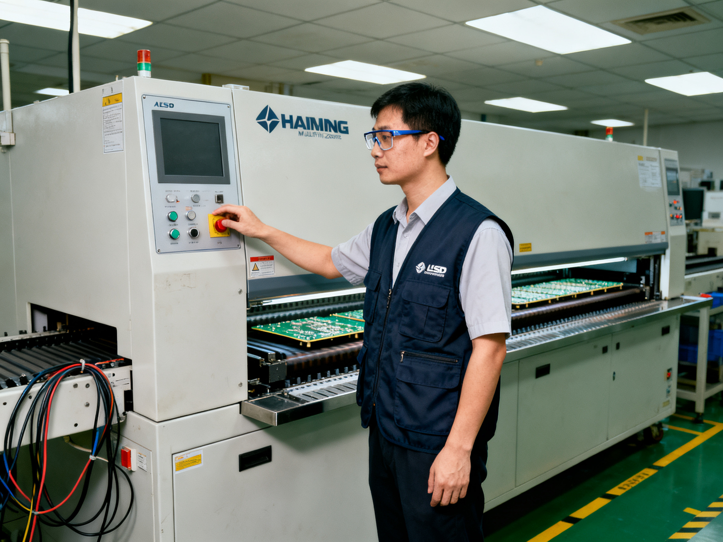
Here is the order that works for me every time.
Step 1: Write down your constraints before touching the oven
Open a worksheet and record the limits you have to hit. Do not skip this, because the whole point is to end with a profile you can defend.
- Solder paste data sheet: peak temperature range, time above liquidus, ramp and soak guidance
- Alloy liquidus: 217 °C for SAC305, 183 °C for Sn63/Pb37
- Most temperature-sensitive component: maximum body temperature and moisture sensitivity level per J-STD-020 and J-STD-033
- PCB construction: laminate, copper weight, number of layers, surface finish
- Customer requirements: any drawing-specific or quality-plan limit
If two limits conflict, you have a process design problem, not a profiling problem.
Step 2: Choose the right thermocouple locations
This is where profiles go wrong most often. A single thermocouple in the middle of the board tells you almost nothing.
Your channel list should cover the cold spots and the hot spots:
| Location | Why it matters |
|—|—|
| Coldest joint, usually the far edge from the heater | Where the joint actually fails to form |
| Hottest joint, usually a small part near a heater | Where component damage happens |
| Largest ground plane or exposed pad | Highest thermal mass, lags chamber air |
| Shadowed part near a tall connector | Blocked airflow and radiation |
| Small 0402 or 0201 passive | Heats fast, burns first |
| Package body on the most sensitive part | The number that can ruin a part |
On one recent qualification we started with four channels and found a 26 °C spread between the largest exposed pad and the far-edge 0402. Adding two channels at the shadowed connector revealed the real problem: airflow blockage, not a zone setpoint issue. Adjusting the recipe alone would never have fixed it.
Step 3: Mount the thermocouples properly
Use fine-wire thermocouples, and note that your attachment method changes the reading. KIC’s thermocouple tactics study covers the practical differences between solder, tape, and adhesive attachment. Whatever you pick, use the same method for every comparison run and record wire type, gauge, junction location, and attachment material.
Step 4: Set conservative starting points
Start mid-window on zone setpoints and pick a conveyor speed that gives you a cycle time with margin. The goal of the first run is data, not perfection.
Step 5: Run, compare, and change one variable
Run the profiler at production speed after the oven has stabilized. Then compare every metric against your worksheet: ramp slope, soak time and temperature, peak, time above liquidus, cooling rate.
Change one thing at a time. If you move the soak setpoint and the peak setpoint together, you learn nothing about which one helped. And when a defect appears, resist the urge to change the recipe first. Most bridging and voiding traces back to stencil and placement, not to heat.
Step 6: Prove repeatability
Run the profile three times minimum. A single good trace is luck, not a process. Record peak variation, time above liquidus variation, and cooling variation, then set pass or fail bands around them. IPC-7530 treats each fully populated assembly as needing its own temperature versus time plot, which is exactly why repeat runs matter.
Sign-off checklist
Before you release the recipe, confirm that:
- Every specified location meets its limits across at least three consecutive runs
- Peak and time above liquidus sit in the middle of the paste supplier’s window
- The coldest joint still clears liquidus with margin
- No component location exceeds its rating
- Exit temperature is within the handling limit
- Raw traces, thermocouple map, paste lot, and oven serial number are filed
- The recipe is locked and cannot be edited without an audit trail
Store that record with the oven. When someone asks six months later why the recipe looks like that, the trace file answers in seconds.
Ready for the hard part? Next section covers what to do when the profile is right on paper and the defects still show up.## 6. Troubleshooting and Optimizing an SMT Reflow Oven Profile
The profile looks perfect on paper. Yet the AOI report still shows voids, and the returns pile up with cracked packages. This is where most lines get into trouble, because the instinct is to nudge a setpoint and see what happens.
Nudging blindly is how a line ends up cooking one board and cooking the next.
Work symptom to cause, not cause to guess
The trouble with thermal defects is that most of them look thermal but are not. So before touching a setpoint, walk the symptom down through five layers: profile, printing, placement, materials, and design.
| Symptom | Check first | Only then look at |
|—|—|—|
| Cold joints and opens | Paste activity, pad finish, paste volume | Time above liquidus, peak |
| Voiding in BGA or QFN | Stencil aperture, paste volume, stencil release, outgassing | Peak, soak, ramp aggression |
| Head-in-pillow | Warpage, coplanarity, placement offset, oxidation | Heating and cooling rate |
| Solder balls | Paste slump, stencil release, humidity | Ramp rate, soak time |
| Bridging | Printing, registration, pad geometry | Rarely thermal |
| Tombstoning | Paste volume per pad, placement offset, land pattern | Pad heating balance |
| Cracks or delamination | Bake history, moisture sensor data | Total thermal exposure |
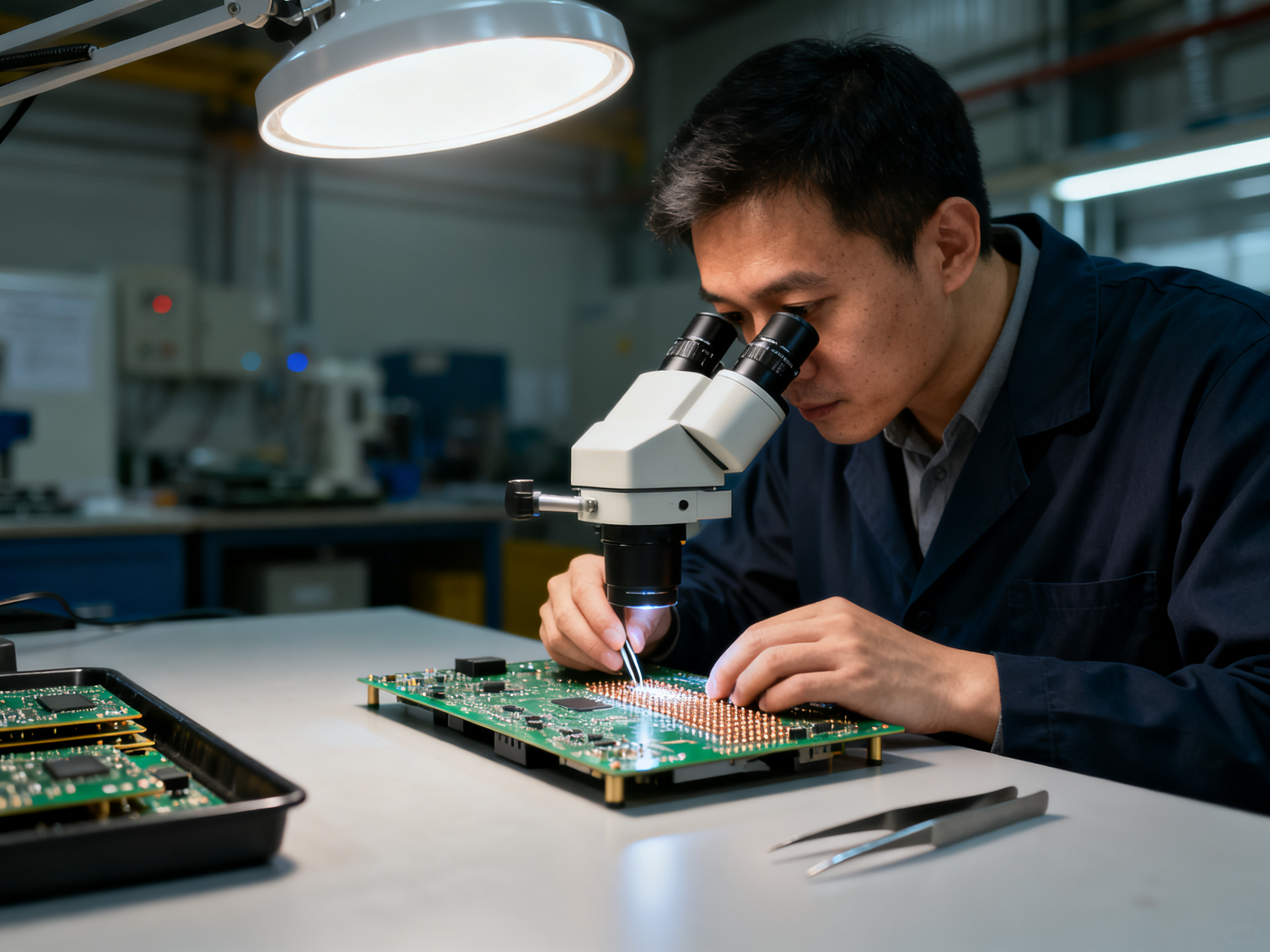
Bridging is the classic trap. When two 0.5 mm pads merge, the first instinct is to lower the peak. But bridging usually starts at the printer, and lowering the peak just risks cold joints. The research on reflow profile and paste volume effects in QFN voiding makes the same point: paste volume and aperture geometry usually dominate the result.
From Our Experience: On one line we chased a cold joint at the board edge for two weeks, changing zone setpoints each time. The actual cause was a 26 °C gap caused by airflow blocked by a tall connector, visible only after a second thermocouple was placed at that shadowed location. One recipe change fixed what four recipe changes could not.
The lesson: change one variable at a time, and let the evidence point at the layer.
Balancing yield against throughput
Speeding up the conveyor shortens time above liquidus. Slowing it down increases it. Every adjustment is a trade, and the limits are hard: paste peak window, component maximum body temperature, and the cooling limit for your heaviest board.
A practical order of attack:
- Fix the biggest gap first, usually a cold joint far from the heater.
- Move the soak window rather than the peak, since soak fixes thermal equalization with less component stress.
- Use peak last, in small steps, because peak is the setting that damages parts.
- Adjust cooling only after ramp, soak, and peak are stable.
- Change airflow or zone balance before changing setpoints, since airflow is a hardware cause.
Keep the whole curve inside the paste window and the component rating. Never buy yield by moving past a limit.
Keeping the profile under control
A profile is not a set-and-forget artifact. In 2026 most lines run scheduled reprofiling rather than occasional troubleshooting, because IPC-7801 covers reflow oven process control, including baseline verification, periodic checks, calibration, and maintenance.
A workable control plan:
- Reprofile on a schedule tied to production volume, not just on failures
- Reprofile after any maintenance touching heating, cooling, airflow, exhaust, conveyor speed, or controls
- Reprofile after a product, paste, carrier, loading, or orientation change
- Review oven alarms daily and treat repeated alarms as a signal, not noise
- Keep calibration records, as-found and as-left data, instrument IDs, raw traces, and product disposition
- Track time above liquidus and peak as SPC points on a control chart, with action limits
- Feed AOI and X-ray results back into the process review
Do not copy a universal calibration interval from a blog post, including this one. Follow the manuals for your oven, profiler, thermocouples, sensors, and gas system, and record the intervals you actually use.
And remember that a numerically acceptable profile still fails if it produces defects, damaged components, or warpage. The profile sheet passes; the board is the final judge.
If you are rebuilding a line in 2026, ask a supplier such as Shenzhen Chuxin for the factory acceptance test built around your worst-case product, not a generic demo board. Loading the heaviest, largest, most thermally asymmetric board, verifying loaded conveyor speed, and running repeated profiles are what separate a usable machine from a shiny one.
That is the end of the guide. You now have the selection criteria, the cycle time math, the four stages of the temperature curve, a step-by-step profiling routine, and a troubleshooting order that works when defects show up.
7. Nitrogen Reflow, Lead-Free Processing, and Reflow Oven Alternatives
Nitrogen reflow soldering gets pitched as a defect fix. It is not, quite. Nitrogen limits oxidation of molten solder, and that often improves wetting on SAC alloys and widens your process window. But it does not automatically lower BGA or QFN voiding, since those also depend on paste chemistry, stencil aperture design, paste volume, and how you measure the voids. There is also no universal 100, 300, or 1,000 ppm oxygen target. If you want a number, run a controlled air-versus-nitrogen trial on your own boards and set the target from that data.
Quick decision path:
- Defects are oxidation-driven and wetting looks poor? Test nitrogen on a limited line.
- Voiding is the main complaint? Fix the stencil first, then re-test.
- Mixed product mix and high changeover rate? Air often wins on simplicity and operating cost.
Lead-free processing raises the thermal burden on every part. Higher peak temperatures, tighter component limits, different flux behavior, and more energy per board all come with the transition. Compliance runs through EU RoHS restrictions on restricted substances, with separate regimes in China, Japan, Canada, and the US.
| Approach | Control and repeatability | Throughput | Capital and operating cost | Best use | Main limitation |
|—|—|—|—|—|—|
| Forced convection oven | High, multi-zone, repeatable | High | Medium capital, low running cost | Mixed production SMT | Profile work required per product |
| Vapor phase | Very uniform heating | Low to medium | High capital, fluid maintenance | Thermally complex, sensitive parts | Throughput and fluid management |
| Toaster or benchtop oven | Low, no zone control | Very low | Low | Prototypes and repair | Not for BGA or QFN production |
| Hot plate | Low | Manual | Very low | Hand rework, education | No profile, no repeatability |
| Selective soldering | High, but through-hole only | Medium | Medium | Through-hole assemblies | Not a reflow substitute |
So, what is reflow soldering used for in practice? Mass production SMT, plain and simple. Selective soldering is a through-hole process and never replaces reflow. Vapor phase earns its keep on tricky thermal work, not on volume lines.
One last check for 2026 builds: EU RoHS and China RoHS are separate regimes, and neither certifies an oven. Your oven may also need local electrical, gas, and machinery approvals.
If you are comparing quotes now, ask a supplier like Shenzhen Chuxin to quote both air and nitrogen configurations with loaded throughput numbers and FAT criteria built around your worst-case board. That way the decision rests on your product, not on a brochure.## Conclusion: Build a Repeatable Profile, Not a One-Time Recipe
Buying a reflow oven is the easy part. The real work is proving that the machine can hold a validated curve on your product, year after year. The sequence matters: define your assembly constraints, choose enough zone and conveyor capability, instrument the actual board, validate the curve, then control it over time. Skip a step and the numbers on the spec sheet stop meaning anything.
One idea to carry away. It is not the oven setpoint that decides whether a joint is safe and capable. It is the temperature measured inside the solder joint on your board. Setpoints are a request; the profile trace is the answer.
Your next steps, in order:
- Write the constraints: paste window, liquidus, most sensitive component, board construction
- Size the oven: heated length, loaded conveyor speed, zone breakdown, worst-case board mass
- Profile the product: four to six thermocouple channels, cold spot, hot spot, ground plane, shadowed part
- Validate repeatability: three runs, defined limits, locked recipe with traceability
- Document the qualification plan: reprofiling triggers, calibration records, defect feedback loop
Bring this same checklist to every vendor so you compare like with like, and make the factory acceptance test run on your heaviest, most thermally asymmetric board rather than a demo panel. IPC-7801 covers the process control side of that work.
Want help building the spec? Shenzhen Chuxin can run a line assessment, a profiling trial on your samples, and a specification review for lead-free reflow, wave soldering, or a full SMT line integration project.