
Published: 25 May 2026
Reading Time: 15 minutes
Reviewer: Simon Scrapes, Founder
Introduction to Reflow Ovens
Think about the last time you dropped your phone. Maybe it landed screen-down on concrete, or took a tumble down the stairs. Somehow, the tiny components inside kept working perfectly. That reliability starts with a machine most people never see: the reflow oven.
Reflow oven soldering is the backbone of modern electronics manufacturing. It’s what holds together everything from your smartwatch to car control systems, and understanding how these machines work has become essential for anyone in precision assembly.
In this guide, we’ll walk through everything you need to know about reflow ovens. We’ll cover how reflow ovens work, how to set up the perfect reflow oven profile, and the common problems that trip up even experienced technicians. Plus, we’ll dig into nitrogen reflow systems and calibration best practices that can save you hours of frustration on the production floor.
Jace Liu is a seasoned engineer specializing in Surface Mount Technology (SMT) with over a decade of experience in precision soldering techniques and SMT equipment optimization. As a technical advisor to several high-tech manufacturers, Jace brings unmatched expertise in reflow oven operation and troubleshooting.
Whether you’re running a desktop reflow oven in a small workshop or managing a full SMT production line, this article has something for you. Let’s get started.## How Reflow Ovens Work and Key Principles
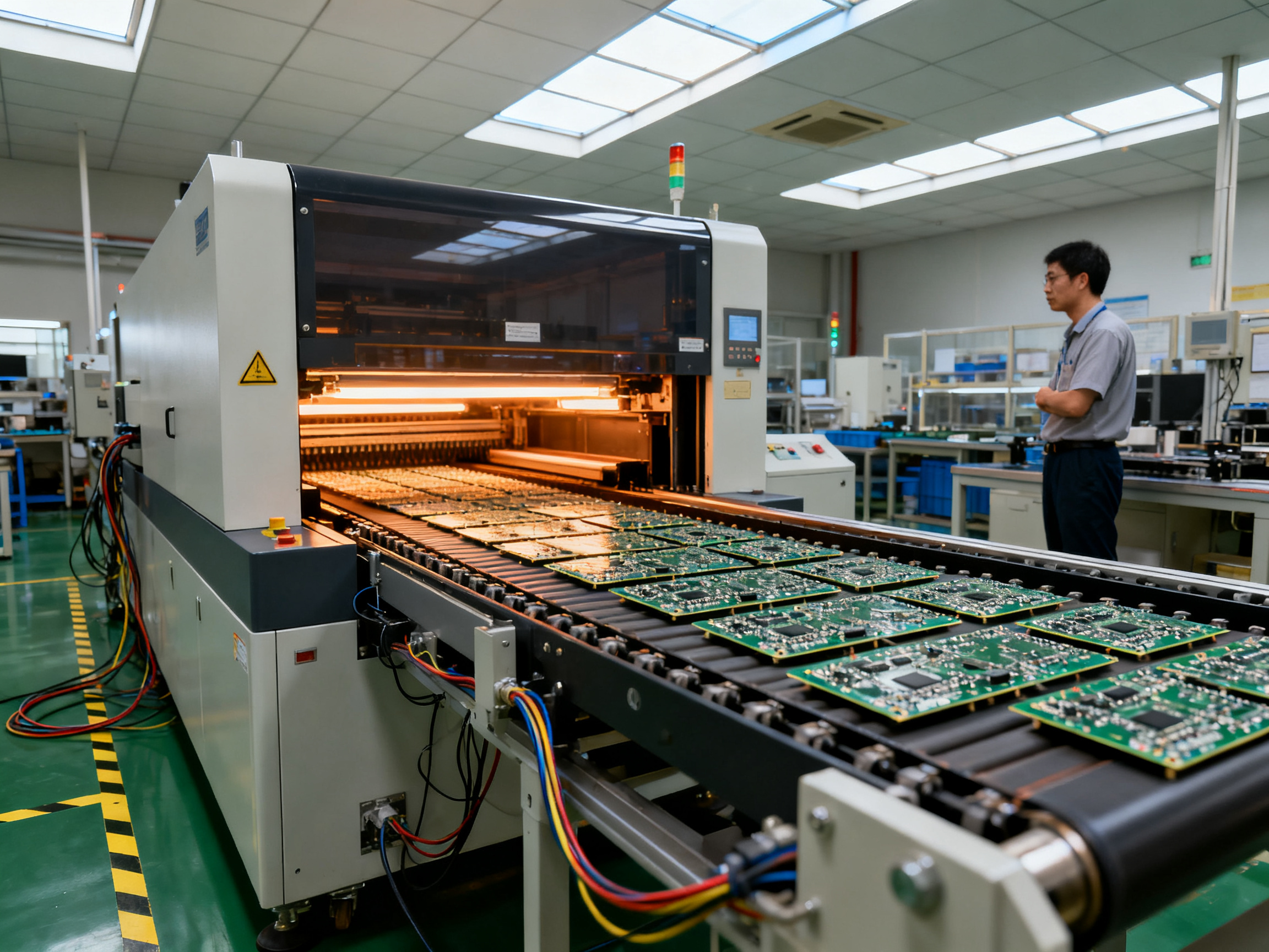
A reflow solder oven is basically a fancy convection heater with a conveyor belt. PCB boards slide through different temperature zones, getting heated up and cooled down in a very specific way. That’s the simple version. The real magic happens in how precisely you control those temperatures and timing.
A reflow oven in SMT processes creates reliable electrical and mechanical connections between surface-mount components and a PCB by heating the board in a controlled temperature profile. The reflow oven performs key steps including preheating (to avoid thermal shock), soak (to equalize temperatures), reflow (melting solder to form metallurgical bonds), and cooling (to solidify the solder joints) 1.
The Four Stages of Reflow
Picture this. Your board enters the oven on a conveyor. Here’s what happens next:
-
Preheat Phase: The board gradually heats up, usually to around 150 degrees Celsius. This step prevents thermal shock that could crack components or damage moisture-sensitive parts.
-
Soak Phase: Temperature stabilizes between 150 and 200 degrees Celsius. This lets all components reach the same temperature before things get really hot. Flux in the solder paste activates during this stage too.
-
Reflow Phase: This is where peak temperature happens, typically between 217 and 250 degrees Celsius depending on your solder type. The solder melts and flows, creating those all-important metallurgical bonds.
-
Cooling Phase: The board cools down rapidly. This solidifies the joints properly. Too slow, and you get weak bonds. Too fast, and thermal stress becomes a problem.
The main components that make this happen include the transfer system (conveyor), heating zones, cooling system, and a control system that manages temperature and speed 2.
Standard Ovens vs. Nitrogen Reflow Ovens
Regular reflow ovens use forced hot air circulation. Nitrogen reflow ovens add something to the mix. They introduce nitrogen gas into the heating zones, creating a low-oxygen atmosphere. This reduces oxidation during soldering, improves solder wetting, and minimizes defects like dull joints or excessive intermetallic growth 3.
So how does a nitrogen reflow oven work? It works pretty much like a standard reflow oven during the heating and cooling phases, but you also need to monitor gas flow. The trade-off is cost versus quality. Nitrogen systems are more expensive to run, but for high-reliability products like aerospace or medical electronics, they’re often worth it.
Why Temperature Uniformity Matters
Here’s a thing that trips up a lot of people. You can have the perfect reflow profile on paper, but if your oven doesn’t distribute heat evenly, you’re going to have problems. Uneven heating causes tombstoning, bridging, and cold joints 4.
We often see this with newer technicians who focus only on peak temperature. They forget that the board temperature might vary by 10 or even 20 degrees between zones. For high-density assemblies with BGA components, that variation is unacceptable.
Expert Tip: The importance of temperature uniformity in PCB soldering cannot be overstated. Even a 5-degree variance across a large board can result in intermittent failures that are nearly impossible to diagnose. Always verify your oven’s thermal mapping before running production.
Modern reflow ovens typically have between 4 and 12 heating zones, plus cooling zones. More zones mean better control over the thermal profile, which matters a lot when you’re working with mixed component technologies on the same board.## Step-by-Step Guide: Optimizing Reflow Profiles
Here’s the thing. A reflow profile isn’t just a temperature chart your oven spits out. It’s a roadmap that tells your machine exactly how hot to get, how fast to heat up, and how quickly to cool down. Get this wrong and you’ll spend more time reworking boards than actually producing them. Get it right and your defect rate drops through the floor.
A reflow profile defines the precise thermal journey your PCB takes through the oven. It controls the rate of temperature change at each stage, the time spent in each zone, and the peak temperature reached during soldering. Think of it like baking a cake. You can have the best ingredients in the world, but if your oven temperature is wrong, you’re going to get a burnt or raw mess every single time.
Building Your First Profile from Scratch
Let me walk you through how to set a reflow oven profile that actually works in 2026.
First, you need to know your solder paste specifications. Every manufacturer prints this information right on the datasheet. Look for the “reflow window” which tells you the minimum and maximum temperatures your solder can handle. Most lead-free pastes like SAC305 want a peak around 245 to 250 degrees Celsius.
Next, consider your board and components. Thicker boards hold heat longer, so they need slower ramp rates. Moisture-sensitive components like BGAs have strict limits on how fast they can heat up. FR4 boards are pretty forgiving, but high-frequency materials and metal-core PCBs behave completely differently.
Here’s where most people mess up. They grab a generic profile from the internet and run it without adjustment. Then they wonder why their board has tombstoning on one job and cold joints on another. The truth is, every assembly is unique. Your components, your board thickness, your paste, and even your oven all factor into the equation.
Reading and Adjusting Profile Zones
Modern reflow ovens split the thermal process into distinct zones. When you look at a profile chart, you’ll see temperature plotted against time. The curve shows your heating rates, soak duration, and peak temperature.
The preheat zone should ramp slowly, usually 1 to 3 degrees per second. Push it faster and you’ll shock components. The soak zone typically spans 60 to 120 seconds, giving flux time to clean those metal surfaces. The reflow zone peaks and then drops, and the cooling zone should fall at 4 degrees per second or less to prevent thermal stress.
When adjusting profiles, I always start with small tweaks to the peak temperature, maybe 5 degrees at a time. Too hot and you risk component damage. Too cold and the solder won’t melt properly. You’ll see this as a “cold joint” problem where the connection looks dull and grainy instead of shiny and smooth.
We run into this constantly when helping manufacturers optimize their SMT reflow oven process. One client was fighting a 3% defect rate until we adjusted their cooling rate by just 2 degrees per second. The fix took 20 minutes and saved them thousands in rework costs.
Pro Insight: Common optimization mistakes and how to avoid them include ramping too fast in preheat (causes component stress), ignoring the soak phase entirely (leads to inconsistent reflow), and setting peak temperature based on the hottest component rather than the solder paste requirements. Always match your profile to your paste datasheet first, then fine-tune for your specific board assembly.
Calibration and Monitoring Techniques
If you’re not regularly calibrating your reflow oven, you’re basically guessing. Temperature sensors drift over time, and conveyor speeds change with wear and tear. A yearly calibration might have been acceptable five years ago, but modern high-density assemblies demand quarterly checks at minimum.
The gold standard is running a bare board with thermocouples attached at multiple points. This gives you actual temperature data from inside the oven, not just what the controller thinks is happening. Large boards especially can have 10 to 15 degree differences between the leading edge and trailing edge.
You should also track your profiles over time. Keep a log of every profile you run, including the date, board type, and any adjustments made. When problems pop up, this history tells you what changed. Did you recently swap solder paste vendors? Did the oven get moved or recalibrated? Data beats guesswork every single time.
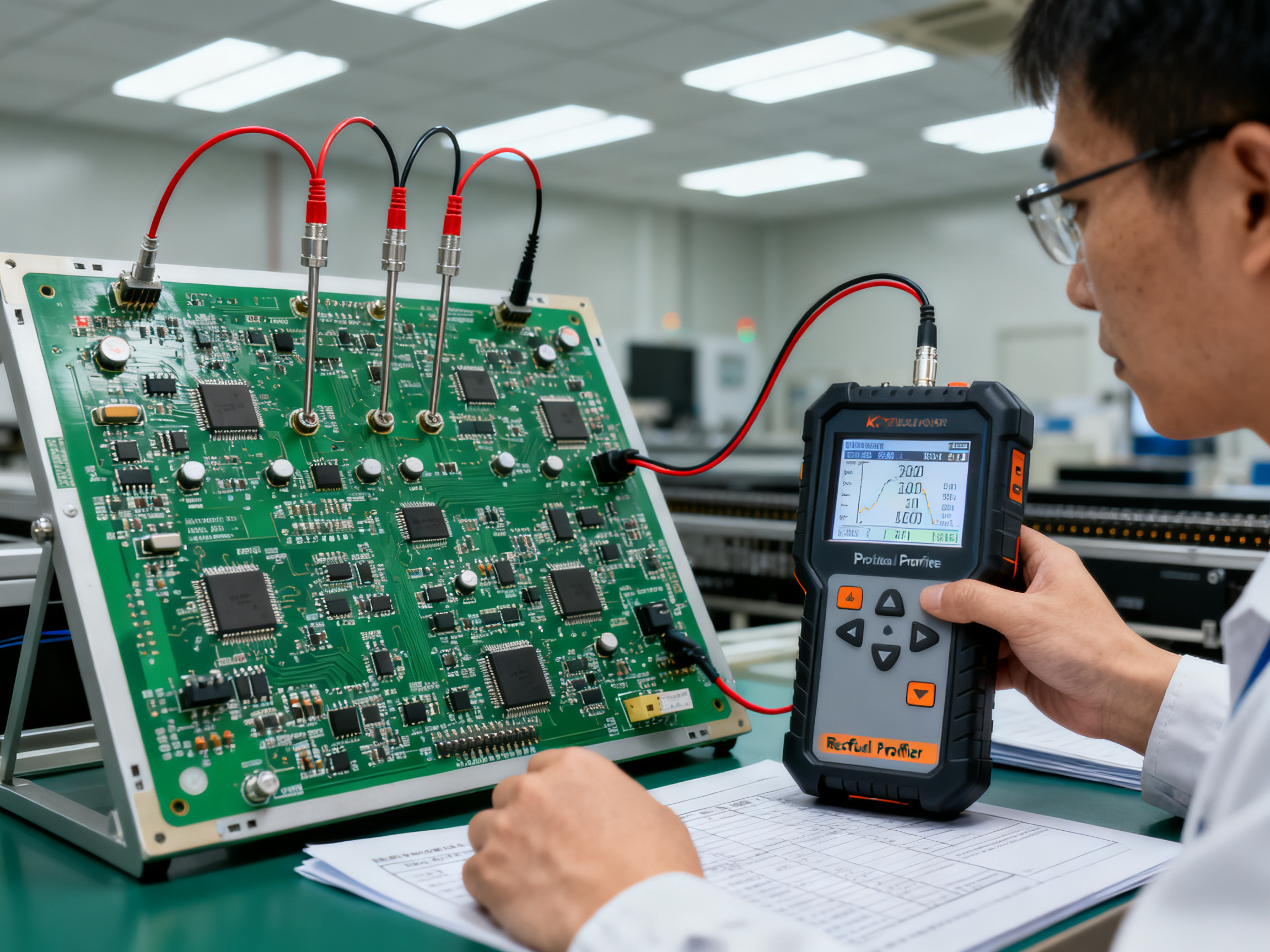
Most professional setups use SPC (Statistical Process Control) software that monitors each board in real-time. This catches deviations before they become defects, not after. For pcb reflow machine operations running high volumes, this investment pays for itself within months through reduced waste and fewer customer returns.
Matching Profiles to Your Materials
Not all boards are created equal. A flexible circuit board needs gentler handling than a rigid FR4 assembly. Lead-free solders demand higher peak temperatures than their leaded counterparts, which means your entire profile shifts upward. Mixed technology assemblies with both large connectors and tiny 0201 resistors need profiles that accommodate the most sensitive part.
When calculating reflow oven cycle time, remember that faster isn’t always better. While shorter cycles increase throughput, they also increase risk. The sweet spot balances speed with reliability. For most standard assemblies, a total cycle time between 4 and 6 minutes works well. High-reliability aerospace or medical products often run 7 to 9 minutes to ensure absolute consistency.
One more thing. Always verify your profile against your actual production setup. What works in the morning when the factory is cool might fail in the afternoon when ambient temperatures rise. Consider seasonal adjustments if your facility doesn’t have tight climate control.## Preventing and Troubleshooting Common Reflow Issues
Let’s be real. Even with the perfect profile and a well-calibrated oven, things go wrong. I’ve seen gorgeous reflow profiles completely fail because someone swapped paste vendors without adjusting anything. The good news is that most reflow defects follow predictable patterns, and once you know what to look for, diagnosis gets a lot easier.
This section walks through the most common problems you’ll encounter, how to identify them fast, and what actually works to fix them. No fluff, just practical troubleshooting you can use on the production floor tomorrow.
Common Defects and What Causes Them
Tombstoning happens when small components like resistors or capacitors lift off the board on one side, looking like tiny tombstones. The root cause is usually uneven heating during the reflow phase. One pad heats up faster than the other, creating surface tension that pulls the component upright. It commonly occurs when your ramp rate is too steep, your soak phase is too short, or your pad sizes are mismatched. Larger pads retain heat longer, so if one pad is significantly bigger than its partner, you’ve got a recipe for tombstoning.
Solder bridging creates unintended connections between adjacent pads. This looks bad under inspection and kills your yields. The usual suspects include too much solder paste applied, stencil misalignment during printing, or pad spacing that’s tighter than spec. Sometimes it’s the paste itself, especially if it’s lost viscosity after sitting too long at room temperature.
Voids are gas pockets trapped inside solder joints. You can’t see them without X-ray inspection, which makes them sneaky. They weaken mechanical strength and can cause intermittent electrical failures down the road. Voids form when moisture in components vaporizes during reflow, or when flux doesn’t have enough time to outgas during the soak phase. High thermal mass areas like ground planes are especially prone because they cool surrounding areas unevenly.
Cold joints look dull and grainy instead of shiny and smooth. The solder never fully melted, so the bond is mechanically weak. This typically happens when peak temperature is too low, time above liquidus is too short, or the board entered the reflow zone before reaching proper temperature. Cold joints are electrical time bombs that might pass your initial test but fail in the field.
Poor wetting shows up as solder that beads up instead of spreading across the pad. The surface looks like water droplets on a waxed car. Flux contamination or oxidation on the pad surface prevents the solder from bonding properly. Sometimes it’s the board finish itself, like poorly applied HASL or contamination on ENIG surfaces.
| Defect | Common Causes | Quick Fix |
|——–|————–|———–|
| Tombstoning | Uneven heating, mismatched pads, steep ramp | Extend soak phase, slow preheat rate, check pad balance |
| Bridging | Excess paste, stencil issues, tight spacing | Reduce paste volume, verify stencil alignment, check pad design |
| Voids | Moisture, short soak, high thermal mass | Dry components, extend soak time, reduce heating rate |
| Cold joints | Low peak temp, short time above liquidus | Increase peak temp by 5-10 degrees, lengthen reflow zone |
| Poor wetting | Oxidation, contamination, bad flux activation | Clean boards, verify paste shelf life, check flux activity |
Diagnostic Approach That Actually Works
Here’s my standard process when defects start appearing in production. First, I grab the last 10 boards that failed and look for patterns. Are the bad joints concentrated in one area of the board? One specific component type? One operator’s shift? This narrows things down fast.
Temperature logging is your best friend. If your reflow oven doesn’t have built-in logging, stop reading this and go set that up right now. Every profile run should generate data you can review later. When problems pop up, you compare current logs against known-good logs from when yields were acceptable. Things drift slowly, so you might not notice a 3-degree shift in peak temperature until it’s causing 5% defects.
Visual inspection under magnification catches most issues, but it’s not enough for everything. BGA components hide their failures completely. If you’re running BGA assemblies, budget for X-ray inspection. Full confession here: I skipped X-ray inspection for months because the machine sat idle and I thought visual inspection was sufficient. That cost us a $40,000 recall. Don’t be me.
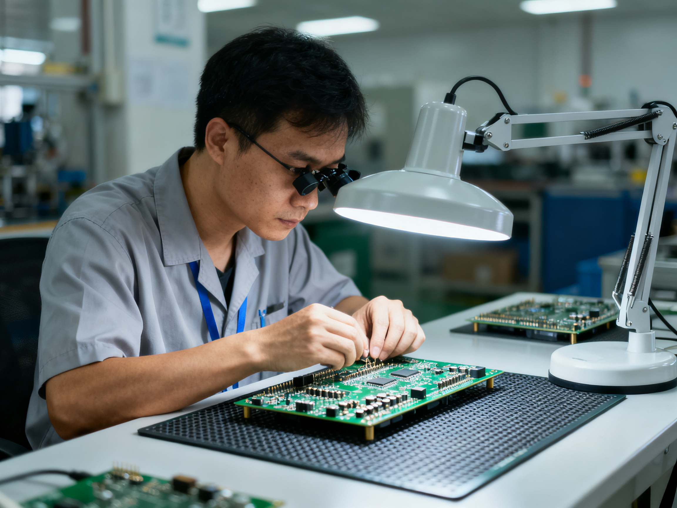
From Our Experience: Diagnosing defects in BGA components requires X-ray inspection, period. Common issues include opens under the corner balls, voids in thermal pads, and misalignment that’s invisible from the top. We recommend running X-ray checks on at least 5 boards per lot for high-reliability products. For consumer electronics, sampling every 20th board works if your paste process is stable.
Practical Steps to Reduce Your Defect Rate
Start with your incoming materials. Components that have been sitting in warehouse conditions for months absorb moisture. BGA packages especially need baking before reflow if they’ve been exposed to humidity. Most manufacturers specify dry storage requirements, but these get ignored constantly. Make baking a standard step in your receiving process for moisture-sensitive devices.
Stencil maintenance matters more than most people realize. Worn stencils accumulate paste residue around apertures, changing deposit volume. Old stencils develop gumming that affects release characteristics. We replace stencils based on shot count rather than visual condition because by the time you see problems, you’ve already made dozens of bad boards.
Conveyor speed consistency affects reflow more than people expect. Belts stretch and wear, motors lose calibration, and product weight changes heating dynamics. A loaded board weighs more than an empty one, which sounds obvious but gets forgotten when you’re running mixed assemblies. If you switch between light and heavy boards without adjusting speed, your profiles will be wrong.
Finally, create a defect log that tracks what failed, when it failed, and what you changed. Patterns emerge over time that single data points never reveal. Maybe your defect rate spikes every Monday after the weekend shutdown. That points to startup procedures, not the reflow profile. Maybe problems appear only on the first shift. That suggests operator training gaps.
When to Call for Support
Some issues go beyond adjustment. If you’ve optimized profiles, verified calibration, checked materials, and still see defects above 1%, it’s time to look at your equipment. Heating elements degrade unevenly in older ovens, creating hot and cold spots that profiling software won’t catch because it measures at fixed points. Conveyor alignment issues cause boards to enter zones at angles, exposing one edge to higher temperatures first.
For manufacturers running pcb reflow machine operations with complex assemblies, partnering with equipment specialists for periodic thermal mapping makes financial sense. We recommend annual comprehensive mapping for production-critical ovens and quarterly checks for high-volume lines. The cost is trivial compared to defect escape rates that reach customers.
Understanding how reflow oven works at a deep level changes how you approach problems. You’re not just following recipes anymore. You’re diagnosing root causes and making informed decisions. That shift in thinking separates technicians who fight fires daily from engineers who prevent them.
Now that you know what can go wrong, let’s talk about keeping your equipment running at peak performance for years to come.## Maintenance Best Practices for Reflow Ovens
Here’s something nobody talks about enough. You can have the most expensive reflow oven on the market, loaded with zones and fancy software, and if you skip basic maintenance, it will perform worse than a properly maintained budget machine within a year. I’ve seen manufacturers spend $200,000 on a new SMT line and then wonder why their yields are terrible. The culprit? Dirty heating elements and calendars that haven’t been checked since installation.
Maintenance isn’t glamorous work. Nobody gets excited about cleaning thermocouples or checking conveyor belt tension. But it’s the difference between a reflow oven that hums along producing perfect joints and one that randomly ghosts you with defects nobody can explain. Let’s walk through what actually matters.
Daily Checks That Take Five Minutes
Before each shift, spend literally five minutes on visual inspection. Look at the conveyor belt for debris or buildup. Check that the heating elements look clean, not coated with flux residue from years of production. Listen for unusual sounds from the conveyor motor. These checks take no time, but they’ll catch 80% of problems before they become production headaches.
Temperature logging should be running on every single board. If your pcb reflow machine doesn’t have this capability built-in, add it. There are third-party solutions that work with most setups. No excuses here in 2026. Data wins arguments, especially when you’re trying to figure out why Tuesday’s batch had twice the defect rate of Monday’s.
Flux accumulation is the silent killer of reflow oven performance. It builds up on heating elements, thermocouples, and inside the chamber. Over time, this residue insulates surfaces, causing temperature readings to drift and heating efficiency to drop. I recommend wiping down accessible surfaces with appropriate cleaning solution at the end of each shift. Yes, every shift. Your future self will thank you.
Weekly and Monthly Maintenance Tasks
Once a week, run a dry-board thermal profiling test. This means running an empty board with thermocouples attached through your oven and comparing results against your established baseline. You’re looking for drift, typically 3 to 5 degrees over time. If you see more than that, it’s time to dig deeper.
Conveyor belt tension matters more than people realize. Belts stretch with use, and a loose belt causes boards to wobble through zones. That wobble means inconsistent thermal exposure. Check belt tension weekly and adjust according to your oven’s manual. Most systems have simple tensioning mechanisms that take minutes to adjust.
Monthly, pull out the heating chamber covers and vacuum accumulated flux and solder particles. This is dusty work and nobody wants to do it, but the performance difference before and after cleaning can be shocking. We’ve measured 8 to 10 degree improvements in temperature uniformity after a thorough cleaning on ovens that had been neglected for months.
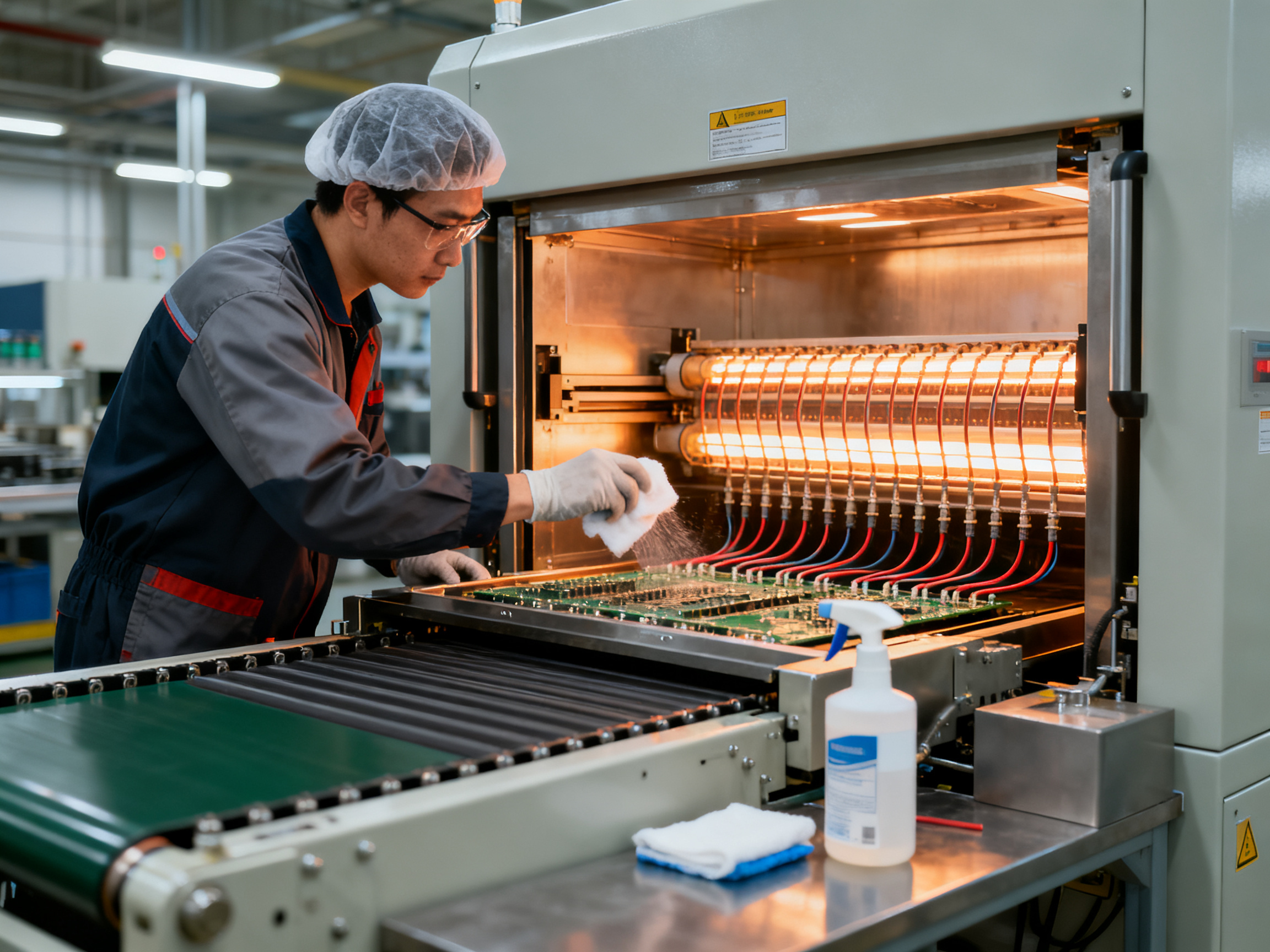
Thermocouple calibration should happen quarterly minimum. These sensors drift, and for smt reflow oven process work, even small errors compound into big problems. Most manufacturers recommend annual recalibration by certified technicians, but we push for twice yearly on production-critical equipment.
Advanced Maintenance Tracking in 2026
Modern reflow solder ovens increasingly include predictive maintenance features. These systems monitor component wear, heating efficiency, and conveyor performance in real-time. They alert you before failures happen, not after you’ve already made hundreds of bad boards. If you’re buying new equipment, prioritize these features. The ROI calculation is simple when you factor in defect escape costs.
For existing equipment, consider adding IoT sensors to track vibration, temperature accuracy, and conveyor speed. This data feeds into maintenance scheduling software that optimizes service intervals based on actual usage rather than arbitrary calendar dates. A machine running three shifts wears differently than one running one shift, so calendar-based maintenance often means over-servicing some equipment and under-servicing others.
Building a Maintenance Schedule That Sticks
Here’s a practical checklist template you can adapt for your facility:
| Frequency | Task | Notes |
|———–|——|——-|
| Daily | Visual inspection | Conveyor, heating elements, unusual sounds |
| Daily | Temperature logging review | Compare against baseline |
| Daily | Clean accessible surfaces | End of shift wipe-down |
| Weekly | Dry-board profiling test | Thermocouple verification |
| Weekly | Conveyor belt tension check | Adjust if needed |
| Monthly | Deep chamber cleaning | Vacuum flux and debris |
| Quarterly | Thermocouple calibration | Certified service |
| Quarterly | Full thermal mapping | Production-critical ovens |
| Annually | Professional service visit | Comprehensive inspection |
The schedule only works if someone actually does it. Assign clear ownership. Make it part of shift handover procedures. And for the love of quality, don’t skip tasks because production is running behind. The 15 minutes you save by rushing will cost you hours of rework later.
A well-maintained reflow oven delivers consistent results year after year. Neglect it, and you’ll constantly fight fires that never quite get resolved. Put maintenance first, and your reflow oven will handle the rest.## Emerging Trends and Concluding Insights
The reflow oven has come a long way since the early days of surface mount technology. What started as simple convection heaters have evolved into precision instruments capable of maintaining temperature accuracy within fractions of a degree. If you’ve made it this far, you now understand the fundamentals: how reflow ovens work, how to set profiles that actually solve problems instead of creating them, and how to troubleshoot issues when they inevitably pop up.
But here’s what excites me about where the industry is heading in 2026.
What’s Coming Next in SMT Reflow Technology
Artificial intelligence is starting to play a bigger role in reflow oven operations. Modern smt reflow oven process equipment increasingly includes machine learning algorithms that analyze thermal profiles in real-time, adjusting parameters automatically to compensate for variations in incoming materials or ambient conditions. We’re not quite at the point where ovens run themselves, but the gap between manual profiling and AI-assisted optimization is narrowing fast.
Advanced sensor arrays are another game-changer. Traditional ovens rely on a handful of thermocouples to infer temperature across an entire board. Newer systems deploy dozens of distributed sensors that create detailed thermal maps for every single panel. This means problems get caught before defects form, not after you’ve already produced a hundred bad boards.
Predictive maintenance has moved from buzzword to reality. Equipment like the solder reflow machine systems from Shenzhen Chuxin Electronic Equipment Co., Ltd. now monitors heating element health, conveyor alignment, and calibration drift continuously. Instead of scheduled downtime for maintenance, you get alerts when actual wear patterns indicate service is needed. This approach reduces unexpected failures and extends equipment lifespan significantly.
Staying Current in a Fast-Moving Industry
The SMT landscape shifts quickly. Lead-free regulations, miniaturization trends, and new component packages like micro-BGAs keep pushing reflow requirements higher. Here’s what I’d recommend for staying ahead.
Join industry associations and attend trade shows when you can. The conversations you have with other technicians and engineers reveal what’s actually working on production floors, not just what vendors claim. Online forums dedicated to electronics manufacturing also provide invaluable real-world troubleshooting advice.
Build relationships with your equipment suppliers. Companies like S&M Co. Ltd. that specialize in pcb reflow machine technology often provide application engineering support as part of their service. Use it. Before launching a new product with challenging thermal requirements, reach out to their technical teams. This kind of collaboration prevents expensive mistakes.
Document everything. Keep detailed records of your profiles, maintenance activities, and defect trends. When new component technologies arrive, your historical data becomes the foundation for developing appropriate reflow profiles instead of starting from scratch every time.
Final Thoughts
Reflow oven soldering remains one of the most critical processes in modern electronics manufacturing. The fundamentals we covered in this guide, from temperature zones to defect troubleshooting, apply whether you’re running a desktop reflow oven in a small repair shop or managing a high-volume production line.
Invest in understanding your equipment deeply. Calibrate regularly. Keep detailed records. And don’t be afraid to reach out for expert support when you’re facing challenges beyond your current expertise.
The machines will keep getting smarter, but the technicians who understand the underlying principles will always be the ones who deliver consistent quality. Keep learning, keep testing, and your reflow results will speak for themselves.
Now get out there and make some solid joints.