
Published: 25 May 2026
Reading Time: 12 minutes
Reviewer: Simon Scrapes, Founder
Why Solder Joint Quality is a Cornerstone of Reliable Manufacturing
You know that sinking feeling when a product fails in the field, only to trace it back to a single weak connection on the circuit board? More often than not, that tiny point of failure is a solder joint that didn’t quite make the grade.
So, what is a solder joint? Put simply, it’s the metal bond that connects an electronic component’s leads to the copper pads on a printed circuit board (PCB). During surface mount technology (SMT) assembly, solder paste gets applied to the pads, components are placed, and then the whole board goes through controlled heating. The solder melts, flows, and solidifies to create both an electrical pathway and a mechanical hold.
That’s a lot riding on something most people never see.
Here’s why it matters. In 2026, automated optical inspection (AOI) systems can catch about 98% of visible solder defects. Sounds reassuring, right? But here’s the less comforting part: stencils alone cause roughly 60% of SMT defects before inspection even happens. That means the quality of your solder joints isn’t just about final testing. It’s about every step in the process.
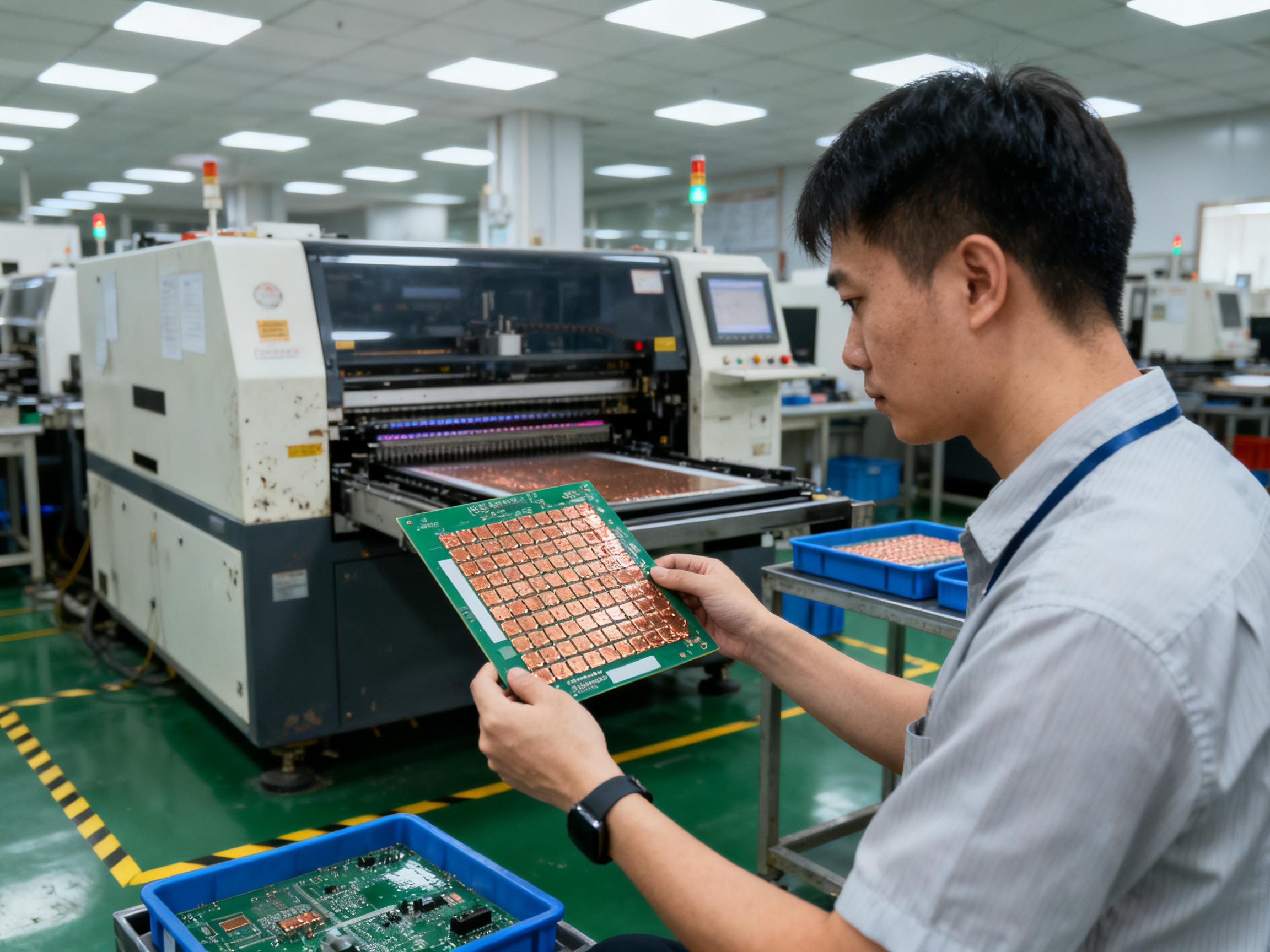
When solder joints fail, they don’t just kill one board. They slow down production lines, trigger costly rework, and in worst cases, lead to product recalls that damage reputations and bottom lines alike.
The good news? Most solder joint problems are preventable with the right techniques and attention to detail.
In this article, we’ll walk through what makes a good solder joint, explore the common pitfalls that create bad ones, and share practical strategies to keep your manufacturing running smoothly. Whether you’re troubleshooting recurring defects or just want to strengthen your quality control, we’ve got you covered.
Jace Liu is a seasoned expert in electronics manufacturing, specializing in surface mount technology (SMT). With extensive experience in precision soldering techniques and a deep understanding of industry trends, Jace provides actionable insights to help manufacturers achieve top-tier product reliability and efficiency.
—## Mastering the Basics: Types of Solder Joints
Not all solder joints are created equal. Depending on what you’re building and how it needs to perform, different joint types serve different purposes. Let’s break down the main ones you’ll encounter in electronics manufacturing.
Butt Joints
Picture two wires or components end-to-end. That’s a butt joint. The surfaces meet flat, with solder filling the gap between them.
Where you’ll see these: connectors, discrete components, applications where space is tight.
The upside? They use minimal board real estate. The downside? Mechanical strength isn’t their strong suit. If your product will face vibration or physical stress, butt joints might leave you exposed.
Lap Joints
Lap joints overlap the two metals being joined. The solder covers the entire overlap area, creating a stronger mechanical bond than butt configurations.
You’ll find lap joints often in through-hole applications and anywhere components need to withstand physical strain.
The trade-off here: they take up more space on the board. But for durability? Way better than butt joints. Electrical contact stays solid too.
Fillet Joints
Here’s where SMT really shines. Fillet joints form when solder creates a smooth, angled connection between the component lead and the PCB pad.
These are the most common solder joints in surface mount manufacturing, and for good reason. They provide excellent mechanical strength, good electrical conductivity, and they’re relatively easy to inspect visually.
Fillet joints work great for most surface mount components. The solder naturally flows to create that characteristic concave profile, which helps with stress distribution during thermal cycling.
Specialty Joint Types for SMT
Modern manufacturing also uses J-lead, gull wing, and pad-in-via configurations depending on the component package and stress requirements.
J-hook joints curl underneath QFP and similar packages, creating a reliable mechanical interlock. Gull wing leads (think SOIC packages) extend outward and down, making them easier to inspect and rework.
| Joint Type | Best For | Strength | Space Efficiency | Inspectability |
|————|———-|———-|——————|—————-|
| Butt Joint | Space-constrained designs | Low | High | Moderate |
| Lap Joint | Through-hole, high-stress apps | High | Low | Good |
| Fillet Joint | Surface mount, general use | High | Moderate | Excellent |
| J-Lead | QFP, memory packages | High | High | Good |
| Gull Wing | SOIC, PLCC packages | High | Moderate | Excellent |
Expert Tip: A good solder joint typically shows complete wetting, where the solder has flowed properly and bonded with both the pad and the component lead. Look for a smooth, concave fillet shape without gaps, voids, or bridging. The joint should have a shiny appearance (for traditional tin-lead) or a slightly duller finish (for lead-free formulations). Any cracks, fractures, or incomplete connections are red flags that usually trace back to temperature profile issues or contaminated surfaces.
Choosing the right joint type depends on your specific application. If you’re manufacturing automotive electronics, you might prioritize mechanical robustness. For handheld devices, space efficiency could be the bigger concern.
What matters most is matching the joint type to your product’s real-world demands. A joint that works perfectly in a climate-controlled office might fail prematurely in an industrial environment with temperature swings and vibration.## Techniques to Prevent Solder Joint Defects
Preventing solder joint defects starts long before the reflow oven heats up. It begins with your material choices, your process parameters, and your understanding of what can go wrong at each stage.
Lead-Free Soldering: What Manufacturers Need to Know
Lead-free solder became the industry standard for most electronics, and it brought some real challenges with it. Tin-silver-copper (SAC) alloys, the most common lead-free formulations, require higher melting temperatures, typically around 217 to 221 degrees Celsius. That’s significantly higher than traditional tin-lead solder, which melts at 183 degrees.
Here’s what that means in practice: your reflow profile needs to account for this temperature jump. Too hot, and you risk damaging sensitive components or creating excessive intermetallic layers. Too cool, and the solder won’t melt properly, leaving you with cold joints and incomplete bonds.
From what we’ve seen, manufacturers who take time to optimize their lead-free profiles actually end up with more consistent results. The learning curve is real, but once you dial it in, lead-free assemblies can exceed the reliability of their leaded predecessors.
One thing to watch: lead-free solder tends to be less forgiving of surface contamination. Make sure your pads and component leads are clean before assembly. Even minor oxidation can prevent proper wetting, leading to weak joints that fail prematurely.
Pro Insight: When working with lead-free solders, avoid the common pitfall of simply raising your peak temperature. Instead, focus on extending time above liquidus. Most SAC alloys benefit from 60 to 90 seconds above 217 degrees Celsius, which gives the solder enough time to flow properly without overexposing components to heat stress. A gradual ramp rate of 1 to 3 degrees per second in the preheat zone also helps activate flux and reduce thermal shock.
Achieving Uniform Heat Distribution
Hot spots in your reflow oven are enemies of quality. When different areas of your board see different temperatures, some joints will be overprocessed while others remain underheated. The result is a mix of burnt pads, lifted components, and cold joints all on the same assembly.
Regular calibration of your reflow equipment matters more than most people realize. We recommend thermal profiling at least quarterly, or whenever you change board configurations or component types significantly. A proper thermal profile map shows you exactly what temperature each zone of your board experiences throughout the reflow cycle.
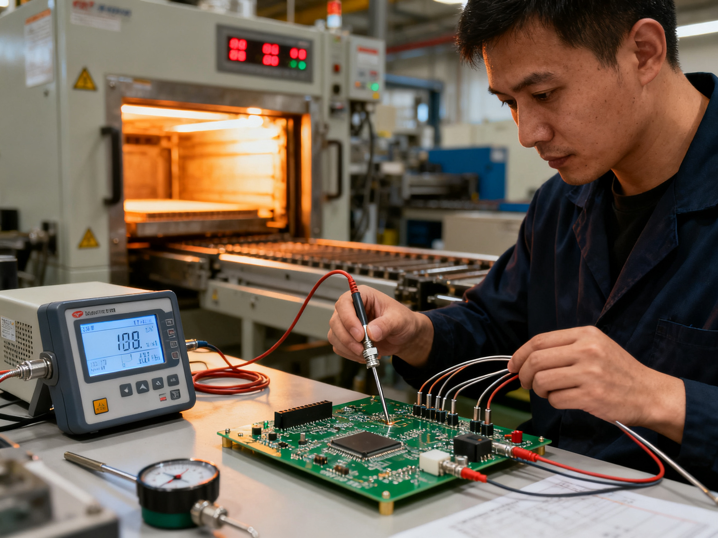
Conveyor speed also plays a huge role. Too fast, and your board doesn’t spend enough time in each thermal zone. Too slow, and you risk overheating everything. Finding that sweet spot takes testing, but it’s worth the effort.
Board support fixtures can help distribute heat more evenly, especially for thin or warped boards. These tools sit underneath your assemblies during reflow and help maintain flatness while promoting consistent thermal transfer.
Addressing Voids and Cracks
Voids are pockets of gas trapped within the solder joint. They weaken the mechanical bond and can create hot spots that accelerate failure. Modern industry standards typically allow voiding up to 25% of the joint area, but lower is always better when your application demands reliability.
Vacuum reflow chambers have become more accessible in recent years, allowing manufacturers to reduce voiding significantly. If you can’t invest in vacuum equipment, optimizing your paste printing and adding a gentle nitrogen atmosphere to your reflow chamber can help minimize gas formation.
Cracks typically appear after thermal cycling, especially when joints experience repeated expansion and contraction. Lead-free solders are more prone to crack formation than tin-lead alternatives due to their higher stiffness. Selecting alloys with small amounts of dopants like nickel or cobalt can improve thermal fatigue resistance considerably.
Stress relief in your board design also matters. Avoid placing heavy components near the board edges, and use adequate standoff heights for parts that might experience vibration. The goal is to minimize mechanical strain on your joints during normal product use.
By paying attention to these factors, you can dramatically reduce your defect rates and build assemblies that last.## Evaluating and Testing Solder Joint Reliability
So you’ve built your boards, your reflow profile is dialed in, and your defect rates look good on paper. But how do you know your solder joints will hold up over time, especially in demanding applications?
That’s where testing comes in. Evaluating solder joint reliability means putting your assemblies through conditions that simulate years of real-world use in a compressed timeframe. It’s not glamorous work, but it’s what separates products that last from ones that fail in the field.
Mechanical Stress Testing
Mechanical testing checks whether joints can withstand physical forces like vibration, shock, and pull stress. Think about products that get dropped, jostled during shipping, or installed in environments with constant motion.
Drop shock testing simulates what happens when a device hits the floor. Boards are subjected to controlled drops from specific heights, and engineers examine which joints crack or separate. For consumer electronics like smartphones, this testing is absolutely critical since devices face daily abuse.
Vibration testing exposes assemblies to sustained shaking across different frequencies. The goal is to identify joints that might crack after months of vibration exposure. Automotive electronics go through especially rigorous vibration testing since engine harmonics can stress solder joints for thousands of hours.
Pull testing measures the force required to separate a component from the board. It’s a straightforward way to quantify mechanical bond strength. Most manufacturers set minimum pull force thresholds based on their application requirements.
We ran pull tests on a batch of BGA assemblies last quarter and found that our nitrogen atmosphere reflow process increased average pull strength by about 23% compared to our standard air profile. That kind of data helps justify process investments.
Thermal Cycling and Stress Testing
Temperature changes cause materials to expand and contract. Since components and boards have different thermal coefficients, this mismatch creates stress on solder joints every time the temperature shifts.
Accelerated thermal cycling (ATC) testing ramps assemblies between temperature extremes, usually from -40°C to 125°C or higher. A typical test might cycle 1000 times or more to simulate years of thermal fatigue in months of testing.
The key metric here is cycles to failure, which tells you approximately how many thermal cycles a joint can handle before cracking. Lead-free solders generally perform well in thermal cycling, though they can be more brittle than tin-lead alternatives.
From Our Experience: When we evaluate solder joint reliability, we typically start with thermal cycling before moving to mechanical testing. Thermal stress often reveals hidden weaknesses that mechanical testing alone might miss. We recommend running at least 500 thermal cycles on any assembly destined for industrial or automotive applications. For consumer products, 200 to 300 cycles usually provides sufficient confidence.
ISO Standards for Solder Joint Reliability
Manufacturing facilities serious about quality follow established standards for testing protocols. IPC J-STD-001 remains the go-to standard for soldered electrical and electronic assemblies, covering everything from material requirements to inspection criteria.
IPC-A-610 provides the visual acceptance criteria that inspectors use to evaluate finished joints. While this standard focuses primarily on inspection rather than stress testing, it establishes baseline quality thresholds that correlate with field reliability.
For more demanding applications, MIL-STD-883 introduces specific test methods for microelectronics reliability, including thermal shock and mechanical shock protocols. Aerospace and military contracts typically require compliance with these standards.
ISO 9001 certification demonstrates that your quality management system follows documented processes for testing and inspection. Many large OEMs won’t work with suppliers who lack ISO certification.
Real-World Performance Evaluation
Lab testing only takes you so far. Real-world performance data comes from field returns, warranty claims, and customer feedback. Tracking failure modes over time helps you identify whether your testing protocols are actually predictive of field reliability.
A manufacturer we worked with discovered their accelerated testing wasn’t revealing a specific voiding pattern that was causing failures at around 18 months of use. Once they correlated field data with their test results, they adjusted their thermal profile and saw failure rates drop significantly.
Continuous improvement means closing the loop between what happens in the lab and what happens at customer sites. Your testing program should evolve based on real-world feedback.
Case Study: S&M Co. Ltd. Quality Assurance Protocol
Shenzhen Chuxin Electronic Equipment Co., Ltd. implements a comprehensive testing approach for their SMT production lines, combining automated optical inspection with targeted stress testing. Their protocol includes thermal cycling validation for every new board configuration, pull testing on sample assemblies from each production batch, and statistical tracking of defect trends over time.
This systematic approach helps them maintain the precision and reliability their customers in consumer electronics, semiconductor, and military electronics manufacturing expect. By catching potential issues before products ship, they reduce field returns and protect their reputation for quality.
Testing solder joints isn’t a one-time activity. It’s an ongoing commitment to understanding how your assemblies perform under stress and continuously improving your processes based on what you learn.## Achieving Long-term Reliability in Solder Joint Applications
Building boards that work is one thing. Building boards that keep working for years, even decades, is a completely different challenge. Long-term reliability is what separates products that earn customer loyalty from those that generate warranty claims and bad reviews.
So what actually determines how long a solder joint will last?
Factors That Affect Solder Joint Durability
Several variables work together to determine joint lifespan. Thermal cycling stands out as the primary culprit in most field failures. Every time a device powers on and heats up, then cools down, the joint experiences stress. Components expand, boards flex slightly, and over thousands of cycles, micro-cracks start forming.
Material choices matter enormously here. Lead-free solders like SAC305 handle thermal stress reasonably well, but they’re more brittle than tin-lead alternatives. If your product will see frequent temperature swings, you might consider adding small amounts of nickel or cobalt dopants to improve fatigue resistance.
Mechanical stress from vibration and physical handling also takes a toll. Products designed for automotive or industrial environments need beefier joint configurations and possibly adhesive reinforcement for heavy components.
Corrosion resistance becomes critical in humid or chemically aggressive environments. Proper conformal coating over the assembly adds protection, but it only helps if the joints underneath are already sound.
Automated Quality Control in 2026
Manual inspection just doesn’t cut it anymore, not at production volumes. In 2026, automated optical inspection catches about 98% of visible defects, which sounds impressive until you realize that stencils alone cause roughly 60% of SMT defects before inspection even happens.
That means your paste printing process deserves more attention than your inspection process. We’ve seen manufacturers invest heavily in AOI systems while ignoring stencil maintenance, and their defect rates barely budge.
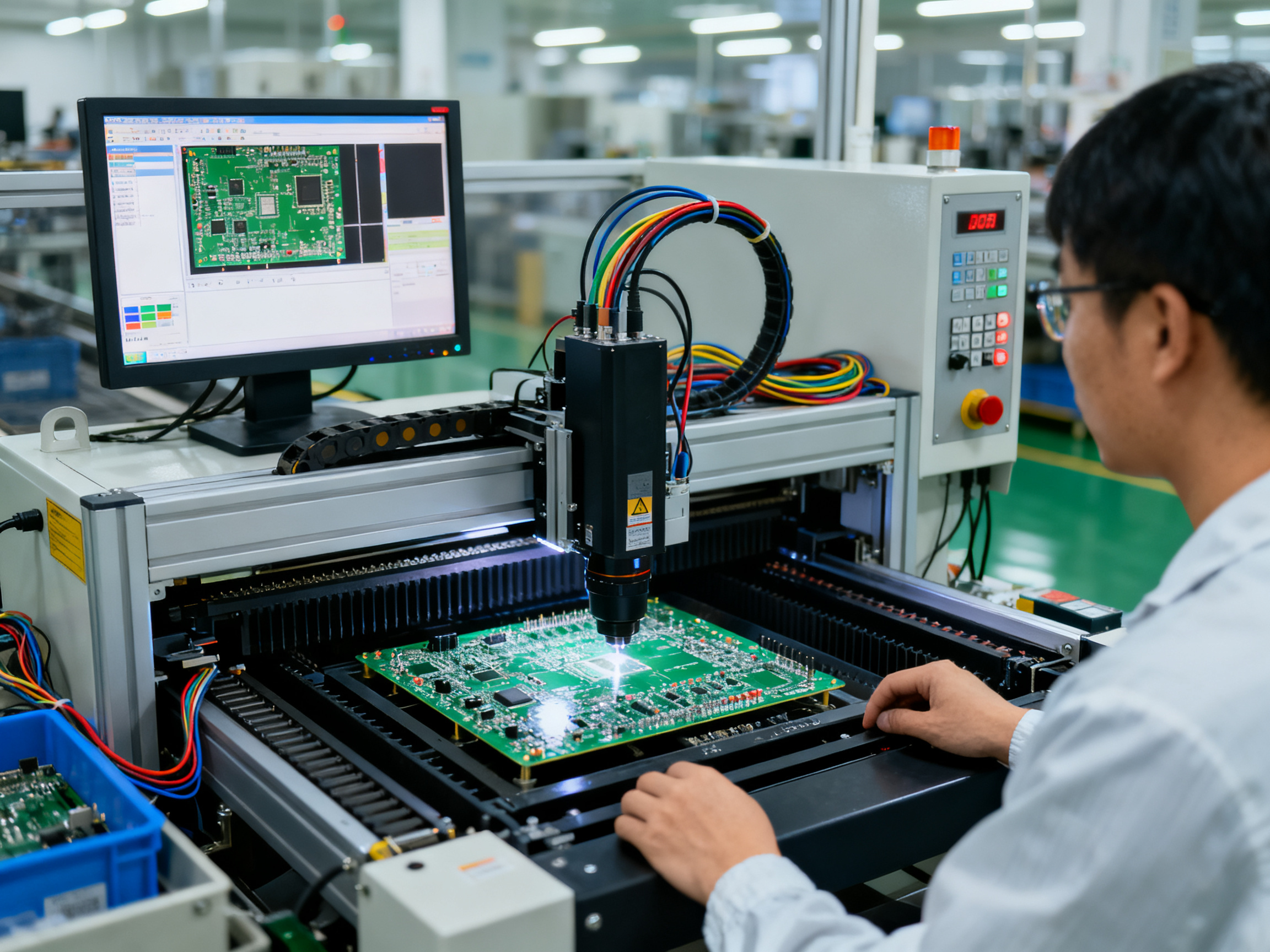
X-ray inspection has become more accessible for checking hidden joints under BGA and QFN packages. These components are nearly impossible to evaluate visually, but X-ray reveals voids, bridging, and misalignments that would otherwise escape detection until field failure.
Statistical process control software now integrates directly with production equipment, flagging trends before they become problems. When your reflow oven starts drifting 2 degrees higher in zone 3, SPC catches it and alerts you before hundreds of boards get affected.
Results from Advanced Soldering Technologies
Manufacturers who have embraced closed-loop reflow control and real-time monitoring report significant improvements in first-pass yield. Fine-tuning your thermal profile takes time upfront, but the payoff in reduced rework and customer returns is substantial.
Vacuum reflow technology, once reserved for aerospace applications, has dropped in cost enough that mid-volume manufacturers can justify the investment. Reducing voiding from typical 15-20% down to under 5% dramatically improves joint strength and thermal conductivity.
The companies seeing the best long-term results treat reliability as a continuous improvement process. They track failure modes, correlate field data with their testing protocols, and iterate on their designs and processes based on what they learn.
Building reliable products isn’t about any single technique. It’s about getting every step right, from material selection through manufacturing and testing. The manufacturers who master this integration are the ones whose products customers trust for years.## Key Takeaways: Your Path to Reliable Solder Joints
So where does all this leave you? If there’s one thing to remember, it’s that solder joint quality isn’t a single checkpoint. It’s a chain of decisions stretching from material selection through years of field use.
Here’s what matters most:
Your stencil is probably your biggest problem. We keep coming back to this because it’s true. In 2026, automated optical inspection catches 98% of visible defects, but stencils alone cause roughly 60% of SMT defects before inspection even happens. If you’re only focusing on your inspection process, you’re fighting the wrong battle.
Lead-free isn’t optional anymore. SAC alloys are the standard now. Yes, they require higher temperatures and more careful profiling. Yes, they’re less forgiving of contamination. But once you dial in your process, they perform well and keep you compliant with environmental regulations.
Test like your reputation depends on it. Because it does. Thermal cycling, vibration testing, and pull testing reveal weaknesses that visual inspection never will. Track your failure modes and correlate them with field data.
Actionable Steps You Can Take This Week
- Check your stencil maintenance log and replace worn stencils
- Run a thermal profile on your reflow oven if it’s been more than three months
- Review your defect data to see if most issues happen before or after reflow
- Consider adding X-ray inspection for BGA and QFN packages
Where Solder Technology Is Heading
Manufacturers are pushing toward real-time reflow monitoring and closed-loop control. Vacuum reflow, once only for aerospace, is becoming accessible for mid-volume production thanks to lower equipment costs. New alloy formulations with better fatigue resistance are in development, and some show promise for handling the thermal demands of high-power applications.
The manufacturers who will stay competitive are the ones treating reliability as a continuous improvement process, not a box to check.
Ready to strengthen your soldering process? Shenzhen Chuxin Electronic Equipment Co., Ltd. offers advanced reflow solutions designed for the precision demands of modern electronics manufacturing. Their lead-free reflow ovens and complete SMT production lines help manufacturers achieve the consistency and quality that reliable solder joints require.
For deeper insights into SMT optimization, explore their case studies and technical resources.
| Best Practice | Impact | Priority |
|—————|——–|———-|
| Stencil maintenance | Reduces 60% of defects | High |
| Thermal profiling | Consistent results | High |
| X-ray inspection | Catches hidden failures | Medium |
| SPC integration | Prevents drift issues | Medium |
| Lead-free optimization | Compliance + reliability | High |