
Published: 24 July 2026
Last Updated: 24 July 2026
Reading Time: 13 minutes
Introduction: Why Pick and Place Programming Defines SMT Line Performance
Picture this. It’s 2am on a Tuesday in a high-volume smartphone assembly plant somewhere in southern China. The line has been running for 14 hours straight when the shift supervisor gets an alert: three boards just failed X-ray inspection with head-in-pillow defects on a BGA package. The root cause turns out to be a rotation value in the pick and place file that was off by 15 degrees. Nobody caught it during programming. Now you’re looking at 200 units of rework, a delivery delay, and a very unhappy customer.
This scenario plays out more often than most people in procurement or executive roles realize. In modern SMT manufacturing, the pick and place programming step is where production lines either succeed or fail before a single component hits the board. Component placement errors account for about 15% of SMT production rework, and in an industry where world-class operations target below 100 defects per million opportunities, that number matters.
BGA and QFN packages are especially unforgiving. These components have hidden solder joints that you cannot see with standard inspection, so placement accuracy has to be right the first time. A misalignment of even 25 microns can create voiding issues or insufficient solder collapse during reflow. When you multiply that across thousands of boards per day, the math gets uncomfortable fast.
But here is the good news. Most of these problems are preventable with the right approach to PCB pick and place files, machine programming, and line integration.
This guide walks you through everything you need to know about SMT pick and place machine programming in 2026. We cover PCB pick and place file formats, how to move data from your CAD software to machine-ready programs, what makes a solid centroid file, how to integrate your pick and place robot with the rest of the SMT line, and how automation ties it all together. Whether you are running a pilot line or a high-volume facility, this content applies to you.
Let’s get into it.
Author Expertise Note
Written by Jace Liu. [Add verified SMT equipment, PCB assembly, or manufacturing automation credentials before publication.]
This article draws on industry benchmarking data, IPC standards documentation, and 2026 SMT process control research to provide a practical foundation for procurement teams, production engineers, and manufacturing leaders evaluating pick and place machine programming, line integration, and automation investments. Credentials and hands-on SMT production experience for the author should be inserted here to support E-E-A-T requirements for this technical content.
From CAD Design to Machine-Ready Pick and Place Program
The pick and place file is only part of the story. Turning that file into a working program on your SMT line requires a few additional steps that are often glossed over in quick-start guides. Getting these steps right the first time can shave hours off of first-article setup and keep your line running at target throughput.
1. Import the Bill of Materials (BOM)
Every pick and place program starts with a clean BOM. The BOM provides component values, reference designators, and package types. Most CAD tools can export a BOM in CSV or Excel format. Before you load it into the machine software, verify that the designators in the BOM match those in your placement file. A single mismatched designator can cause the machine to skip a part or place a component in the wrong location.
2. Map Packages to Feeders
Each component package (QFN-32, SOT-23, 0402, etc.) must be assigned to a specific feeder slot on the pick and place machine. Modern machines support auto-feeder changeover, but you still need to define which feeder holds which package. Some shops keep a master feeder list that maps package types to feeder positions. If you are mixing large and small components, plan your feeder layout to minimize head travel time.
3. Set Board Origin and Reference Points
The machine needs a reference point to align the placement coordinates. Typically this is the board’s lower-left corner, but many designers prefer to use a local origin near the center of the board for easier coordinate math. You must tell the machine which coordinate system you used when exporting the centroid file. Mixing up the origin can shift every placement by several millimeters.
4. Assign Nozzles and Vision Calibration
Different packages require different nozzle types. Smaller components (0201, 0402) need small-diameter nozzles, while larger packages (BGA, QFP) may need vacuum cups or custom grippers. After assigning nozzles, run a vision calibration routine to ensure the machine can accurately locate component leads and fiducial marks. Skipping this step is a common cause of misplacement errors, especially for fine-pitch devices.
5. Simulate Before You Run
Most pick and place software includes a virtual placement mode. Use it. The simulation will flag collisions, missing feeders, out-of-bounds placements, and rotation conflicts before you touch a single board. Two minutes of simulation can prevent a costly crash or a board full of reversed parts.
6. Transfer the Program to the Machine
Once the program passes simulation, push it to the machine controller. For high-mix shops, many machines now support cloud-based program libraries and OTA updates. For older equipment, a USB stick or direct Ethernet transfer still works. Verify the program version on the machine matches what you sent.
Expert Tip: When setting up a new product, run a ‘dry run’ with a blank board or a test fixture that has no components. This lets you watch the machine’s cycle time, confirm feeder sequencing, and catch any unexpected head collisions without risking valuable production boards.
7. First-Article Inspection
After the first board comes off the line, perform a visual check and run it through AOI (Automated Optical Inspection) and X-ray inspection if you have BGA or QFN packages. Compare the placed components to the original CAD data. Any deviation in X, Y, or rotation should be logged and the program adjusted before the line continues.
Closing Thoughts
Moving from a CAD file to a running SMT line is a data‑driven process. The pick and place file, BOM, feeder setup, and machine calibration all need to align. When they do, placement accuracy improves, first‑pass yield rises, and your production schedule stays on track. In the next section, we will look at how closed‑loop automation and AI are reshaping these workflows in 2026.
How PCB Design Software Creates Machine-Ready Placement Data
Here’s where things get interesting. Your CAD software is the birthplace of every pcb pick and place file, and getting this step right saves a ton of headaches later.
The workflow usually goes like this: you design the board in your PCB design tool, define component footprints, place parts on the layout, then export the data your assembly house or pick and place machine needs. The key files that come out of this are your CAD libraries (where component footprints live), the BOM, Gerber files for copper and solder mask, assembly drawings, fiducial marks, and finally the centroid file with X, Y, rotation, and side data for every component.
Thing is, not all PCB software handles these exports the same way. And that matters more than most people realize.
Why Your Component Library Has to Be Spot-On
If your QFN-32 footprint in the library is off by even a few thousandths of an inch, that error follows you all the way through to production. I’ve seen this cause head-in-pillow defects on BGA packages that were nearly impossible to track down until someone checked the original CAD library against the datasheet.
Clean libraries matter. Verify your footprints against IPC-7351 land pattern standards or the component manufacturer’s recommended footprint before you start placing parts. This step feels boring but it prevents real problems on the line.
Software Workflow Differences That Affect Your Output
Different PCB tools export placement data in different formats and with different settings. Here’s a quick comparison of common tools and what to watch for when exporting.
| Tool | Common Export Name | File Extension | Key Settings to Verify | Production Risk If Skipped |
|—|—|—|—|—|
| Altium Designer | Pick and Place Report | CSV, TXT | Origin, units, rotation direction | Wrong rotation values can flip parts |
| KiCad | Component Placement File | CSV, POS | Board origin vs. grid origin | Coordinate mismatch shifts all placements |
| OrCAD/Allegro | Placement File | ALG, CSV | Cadence-native vs. generic export | Proprietary formats may need conversion |
| Eagle/Fusion | Export PCB | CSV, DTS | Library footprint naming | Inconsistent naming breaks BOM matching |
| Generic CAM tools | Centroid Extract | XYRS, CSV | Units (mm vs. inch), decimal places | Decimal truncation causes placement drift |
Most tools let you pick your origin point, layer, and units before exporting. Take 60 seconds to check these settings. I’ve seen entire runs go sideways because someone exported in millimeters when the machine expected inches, or forgot to include rotation data altogether.
Pro Insight: When moving data from CAD to your pick and place machine, always verify the rotation convention. Some tools measure rotation clockwise, others counterclockwise. If your pcb pick and place robot places parts with the wrong orientation, check this setting first before blaming the machine or the operator.
The export itself is just the start. After that, you need to move the file to your machine, verify it loaded correctly, and run first-article inspection to confirm everything matches your original CAD data. We will dig into that workflow in the next section.
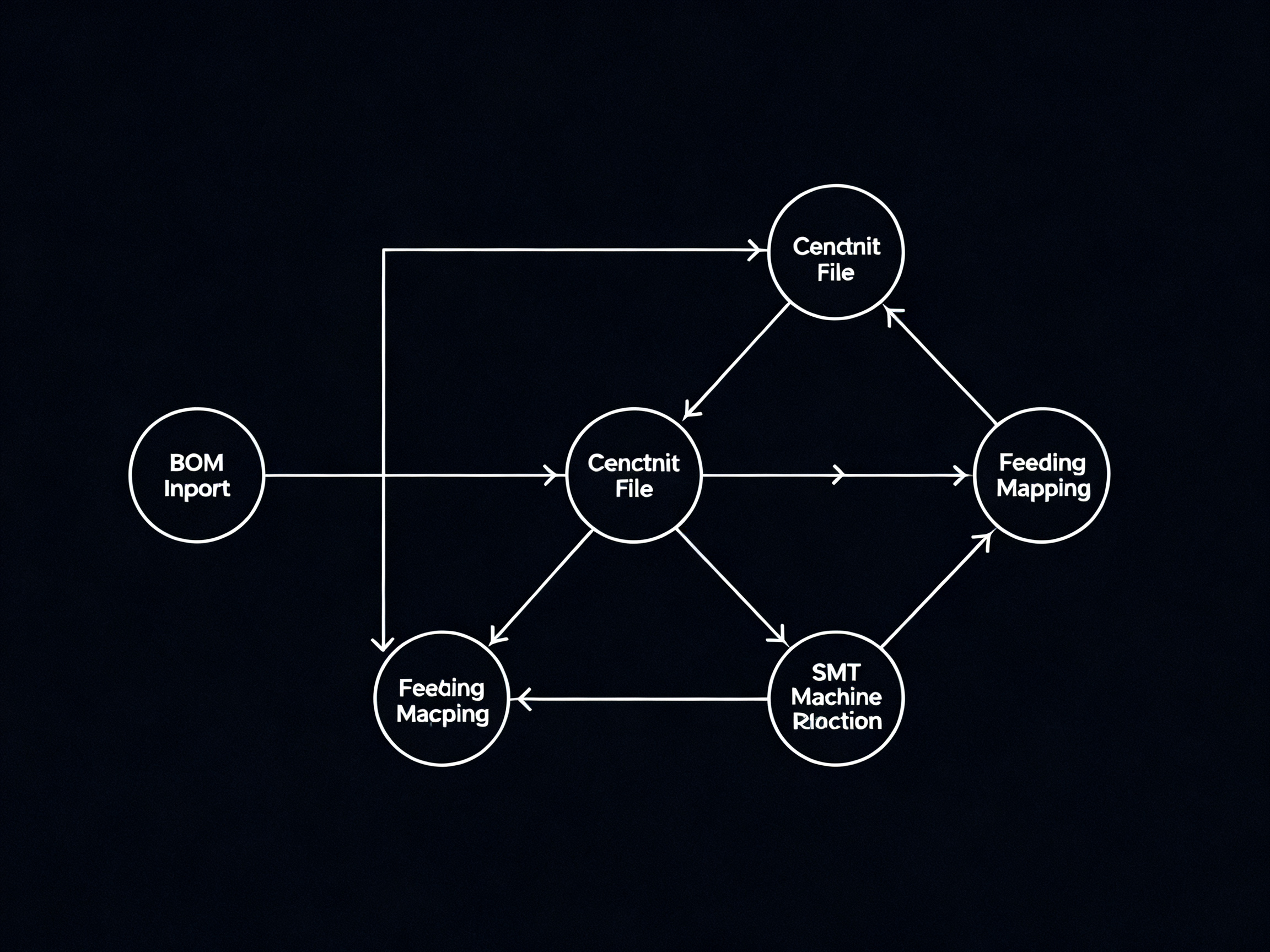
Programming Workflow: From PCB Design Software to Machine-Ready Placement Data
So you have your PCB pick and place file ready. Maybe your CAD tool exported a clean centroid file with all the XYRS data. Now what?
Turning that file into a working program on your SMT line takes a structured sequence. Skip a step, and you will find out the hard way, usually during first article inspection at 3am.
The Full Programming Sequence
Here is how the workflow actually plays out in most shops running SMT pick and place programming in 2026.
Step 1: Import the centroid file.
Your pcb pick and place file comes in as CSV, TXT, or a proprietary format depending on your CAD tool. Load it into your machine’s programming software and verify the units. Most modern machines expect millimeters, but I have seen exports come through in inches more than once. That single mismatch shifts every placement by 25.4 times the coordinate value. Yes, really.
Step 2: Map BOM data to placement records.
The centroid file gives you location and rotation. The BOM tells you what goes there. Match reference designators from the BOM to the placement file. If R1 shows as a 10k resistor in the BOM but the placement file has no value attached, you need to pull that from your CAD libraries or add it manually.
Step 3: Assign feeders and confirm package dimensions.
This is where many first-article failures start. You assign each component to a feeder slot. The machine needs to know if it is picking a 0402 from tape or a QFN-48 from a tray. Package dimensions matter because the machine calculates approach height and placement force based on the component profile. Wrong dimensions mean the nozzle crashes into the part or places it too hard.
Step 4: Select nozzles and calibrate fiducials.
Smaller parts need small nozzles. BGAs and large QFPs need vacuum cups. Some machines auto-select based on package type, but always double-check. After nozzles are set, run fiducial calibration so the machine can align to your board’s actual position, not just the ideal CAD coordinates.
Step 5: Set board origin and panelization.
Tell the machine where zero is. Most designers use the board corner, but some prefer a local origin near the center for easier math. If you are running panels with multiple boards per fixture, you also need to define the array layout and step-and-repeat offsets.
Step 6: Dry run and first article inspection.
Run a dry cycle with no paste or components. Watch for collisions, verify feeder sequencing, and time the cycle. Then run your first real board and inspect it with AOI. For BGA and QFN packages, X-ray inspection is non-negotiable at this stage. One misplaced BGA can take out an entire batch if nobody catches it.
Prototype vs. Mixed-Product vs. High-Volume Programs
The programming workflow changes depending on what you are building.
For prototypes, speed matters more than optimization. You want fast changeover between board spins, minimal feeder reconfiguration, and flexible nozzle options. Most pilot lines use a library-based approach where common packages are preloaded.
For mixed-product runs, program management becomes critical. You need to switch between different board types without losing setup data. Cloud-based program libraries and quick-swap feeder systems help here. The goal is changeover time under 30 minutes.
For high-volume lines, every optimization counts. You tune cycle time, minimize head travel, batch similar components together, and run panelization to maximize throughput. Placement accuracy for BGA and QFN packages gets extra scrutiny because the cost of a defect multiplied across thousands of units is substantial.
Verification Steps You Cannot Skip
Polarity matters. LED polarities, diode orientations, and IC pin 1 markers need to match between your CAD data and the placed board. A reversed LED is an instant reject.
Rotations need a second look. Some CAD tools export rotation clockwise, others counterclockwise. Verify your machine’s convention before running.
Fiducial alignment should be checked on every board, not just the first. Board warpage and panel bow shift fiducial positions enough to matter at fine pitch.
Tray and tape feeder setup has to match the program. If your QFN-32 is in tray position T4 but the program expects it in feeder slot F12, the machine either skips it or grabs air.
Pro Insight: When moving data from CAD to your pick and place machine pcb robot, always verify the rotation convention. Some tools measure rotation clockwise, others counterclockwise. If your pcb pick and place robot places parts with the wrong orientation, check this setting first before blaming the machine or the operator.
For panelization work, confirm that the origin point and array offset are consistent across all boards in the panel. A 0.5mm mismatch here creates problems at depaneling.
And for BGA/QFN components specifically, verify that your vision system is set to look for these packages correctly. Some machines require separate vision profiles for BGAs versus standard packages.
Real-World Example
A few months back, a team I worked with had a first article failure on a QFN-24 package. The rotation looked fine in the CAD file, but the machine kept placing it 90 degrees off. Turns out the export settings in their PCB design software had rotation direction set to counterclockwise, but the machine software expected clockwise. Once we aligned those two settings, everything placed correctly on the first try.
This is exactly the kind of issue that a quick verification step catches, but only if you know to look for it.
In the next section, we will look at how closed-loop automation and AI are reshaping these workflows, and what it means for your line integration strategy in 2026.
Understanding the PCB Pick and Place Robot in Modern SMT Lines
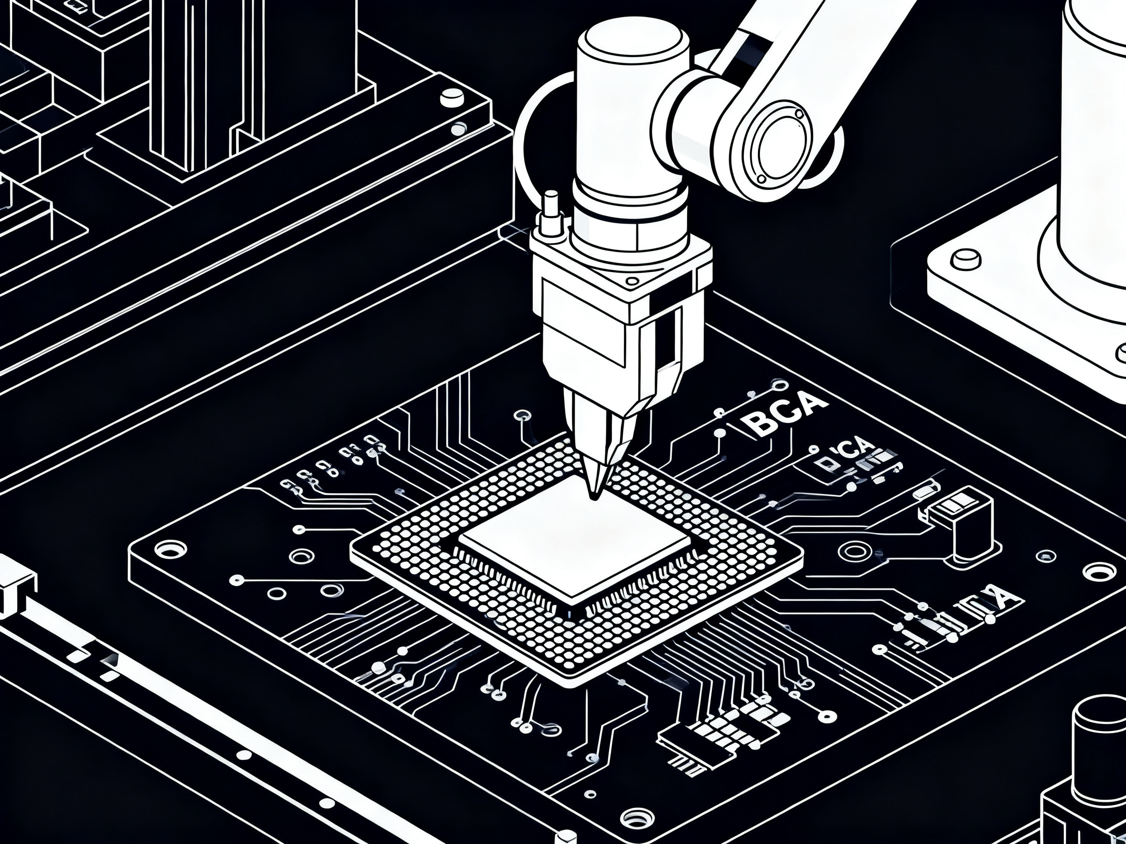
The pcb pick and place robot is the beating heart of any SMT line. It’s the machine that actually picks components from feeders or trays and places them onto your board with sub-millimeter precision. Without it, you have a very expensive pasta printer.
At its core, a pick and place robot combines motion control, machine vision, nozzle systems, feeder mechanisms, and software into one coordinated platform. The motion system moves the placement head across X, Y, and Z axes. The vision system verifies component position and board fiducials. Nozzles grip components during transfer. Feeders supply components in the right order. And the control system ties everything together so each part lands exactly where it needs to go.
Key Performance Variables That Actually Matter
Placement speed gets all the attention. Manufacturers love to advertise 50,000 or 100,000 components per hour. But speed means nothing if accuracy suffers. For modern electronics with BGA and QFN packages, placement accuracy below 25 micrometers is often the real requirement.
Vision recognition has become critical. Modern machines use multiple cameras and sometimes 3D profiling to verify component pickup, alignment, and placement. Without good vision, you get blind placement that can miss shifted parts or rotated packages.
Nozzle compatibility determines what you can actually build. Small 01005 resistors need tiny nozzles. Large connectors need vacuum cups or special grippers. Some machines handle this automatically. Others need manual swapping.
Feeder capacity affects changeover frequency. A machine with 40 feeder slots will need more frequent reloads than one with 120 slots. For mixed-product lines, feeder capacity directly impacts how often you stop production to refill components.
Industry-Specific Robot Requirements
Smartphone manufacturers need maximum speed and fine-pitch accuracy for densely packed boards with BGAs and micro-QFNs. Semiconductor assembly demands even tighter tolerances for advanced packages. Automotive electronics buyers prioritize repeatability and traceability over raw speed. Military and aerospace buyers need extended support lifecycles and strict documentation for compliance.
| Parameter | Entry-Level | Mid-Range | High-Performance |
|———–|————-|———–|——————|
| Placement Speed (CPH) | 5,000-15,000 | 20,000-50,000 | 80,000-100,000+ |
| Placement Accuracy | ±100 µm | ±30-50 µm | ±20-25 µm |
| Component Range | 0402 to 35mm | 0201 to 50mm | 01005 to 75mm |
| Feeder Capacity | 20-40 positions | 60-120 positions | 200+ positions |
| Vision Type | Single camera | Multi-camera + laser | Advanced 3D vision |
| Best Fit | Prototyping, low-volume | Medium-volume, mixed product | High-volume, fine-pitch |
The numbers tell the story. Entry-level machines work fine for prototyping and small batches. High-performance robots justify their cost through speed and accuracy when you’re running thousands of boards per day with challenging packages.
Understanding these specifications helps you match robot capability to your actual production needs rather than buying based on brochure numbers.
Machine Integration: Connecting Pick and Place to the Full SMT Production Line
Your pcb pick and place robot is only as good as the system it talks to. In 2026, SMT lines run on integrated ecosystems where printers, conveyors, inspection machines, and reflow ovens constantly exchange data with the pick and place machine and your factory software. When that communication breaks down, you lose visibility, miss defects, and watch your line efficiency crumble.
Here’s how the pieces actually fit together.
The solder paste printer feeds boards upstream. The pick and place robot receives those boards and places components. Conveyors move everything along. SPI (Solder Paste Inspection) checks the paste before placement. AOI (Automated Optical Inspection) catches placement errors after components go down. The reflow oven fuses everything together. X-ray inspection handles your BGA and QFN hidden joints. And all of that flows into your MES or ERP system for traceability, scheduling, and quality records.
In between, barcode systems track individual boards through the line so you know exactly which unit had which issue at which station.

The Protocol Layer That Makes It All Work
Here’s where most procurement teams get lost. There are three main standards floating around SMT line integration, and they do different jobs.
| Standard | What It Does | Where It Lives | 2026 Status |
|—|—|—|—|
| SMEMA | Basic board handoff signals (ready/not ready) | Legacy electrical I/O between machines | Phasing out but still common |
| IPC-HERMES-9852 | Board ID and metadata transfer between adjacent machines | TCP/IP Ethernet along the line | Replacing SMEMA as the standard |
| IPC-CFX-2591 | Equipment-to-MES data exchange (events, alarms, quality data) | Vertical connection to factory software | Essential for modern lines |
The practical setup in 2026 is Hermes on the line for board transfer, and CFX above the line for factory integration. You typically use both together. SMEMA is the fallback for older equipment that cannot speak Hermes or CFX [1].
From Our Experience: When planning a new line or upgrading an existing one, map your data flow before you buy anything. List every machine that needs to talk to every other machine, what data they need to exchange, and how fast. Then check which protocols your equipment vendors actually support. We have seen lines where the pick and place machine, the reflow oven, and the AOI all came from different manufacturers and could not share data without custom integration work.
Why Integration Decisions Hit Your Bottom Line
Uptime, traceability, and defect rates all tie back to how well your machines talk to each other.
Integrated lines in 2026 benchmark around 75 to 85 percent OEE, with first-pass yield above 98.5 percent and defect rates below 50 DPMO [6][9]. Standalone setups, where machines run in isolation with manual handoffs, typically see 200 to 800 DPMO and OEE around 55 to 65 percent. That gap is not small. It translates directly into labor costs, rework bills, and delivery performance.
For lead-free processes specifically, temperature profiling data from the reflow oven needs to flow back to your MES so you can prove compliance if a customer asks. Hermes and CFX make that data sharing cleaner than the spreadsheet-and-email approach that many shops still use.
The bottom line is simple. Your pcb pick and place robot is a centerpiece, but it is not an island. The smarter your line integration, the more value you extract from that robot and every other machine on your floor.
Automation and Line Integration for High-Volume SMT Manufacturing
High-volume SMT operations in 2026 live or die by how well their systems talk to each other. When your pick and place robot, solder paste printer, reflow oven, inspection machines, and factory software all work as one unit, you see the results in your numbers. Integrated lines benchmark around 75 to 85 percent OEE with first-pass yield above 98.5 percent and defect rates below 50 DPMO. Standalone setups with manual handoffs and isolated machines typically run 200 to 800 DPMO with OEE around 55 to 65 percent. That gap is not theoretical. It shows up in your labor账单, your rework costs, and whether you hit your delivery commitments.
So what does automation actually change in day-to-day operations?
Feeder setup gets faster when machines auto-recognition component packages and load feeder assignments from the job file. Material verification happens automatically through barcode scanning at load, so operators cannot accidentally load the wrong reel. Job scheduling ties directly to production targets, with machines pulling the next program and notifying operators of required feeder swaps before the current job finishes. Recipe management keeps your process parameters (placement speed, placement force, vision thresholds) synchronized across identical lines so that a board built on Line 2 looks exactly like one from Line 1.
Closed-loop inspection feedback is where things get interesting for defect control. When AOI catches a placement issue, that data flows back to the pick and place machine to adjust the next placement in real time. SPI results trigger automatic stencil cleaning cycles. X-ray inspection on BGA packages feeds voiding data back to the reflow profile. The whole line learns from what it sees rather than running blind until first article inspection.
From Our Experience: Planning communication between printers, pick and place machines, reflow ovens, conveyors, inspection systems, and MES platforms takes more upfront engineering than most buyers expect. We have seen lines where each machine came from a different vendor and none of them shared data without custom middleware. Map your data flow before you sign purchase orders. List every machine that needs to talk to every other machine, what data they need to exchange, and how fast. Then verify that your vendors actually support Hermes and CFX protocols rather than assuming everything plays nice together.
Automation Feature to Business Impact
| Feature | Business Impact | Typical ROI Timeline |
|—|—|—|
| Auto-feeder recognition | Cuts changeover time by 30-50% | 6-12 months |
| Barcode material verification | Eliminates wrong-part assembly | Immediate |
| Closed-loop AOI feedback | 40-65% rework reduction | 8-18 months |
| SPI auto-cleaning triggers | Improves paste quality consistency | 6-12 months |
| MES integration for OEE tracking | Identifies bottlenecks in real time | 12-18 months |
| Labor reduction (5-10 to 1-2 operators) | $50k-$150k annual savings per line | 14-22 months |
Practical Constraints You Will Hit
Legacy equipment is the biggest headache. Older machines that cannot speak Hermes or CFX need gateway hardware or manual data entry, which defeats part of the automation purpose. Mixed vendor lines create translation layers. Operator training takes longer when your team has to learn multiple software interfaces. Maintenance planning needs to account for connected systems failing together rather than in isolation. And cybersecurity for your connected factory floor is a real concern now that machines have IP addresses and talk to your MES.
For manufacturers targeting automotive, aerospace, or military customers, compliance with international standards means documentation. Your automation system needs to log every placement, every reflow profile, and every inspection result in a traceable format that customers or auditors can read. That is harder to build with legacy equipment.
The bottom line is this. Automation pays, but it requires upfront planning and realistic expectations about what your existing equipment can do. Start with the highest-impact automation features, like material verification and closed-loop inspection feedback, before chasing full line integration.
Quality Control: Reducing Defects Before, During, and After Placement
Quality control in SMT pick and place programming is not a single checkpoint. It is a continuous process that starts before your pick and place machine pcb board even hits the conveyor and continues long after components land. Get this right and you push your defect rates well below 50 DPMO. Skip it and you will spend your nights chasing rework like the 2am scenario we opened with.
Pre-Placement Controls
This is where most defects are either prevented or guaranteed. Start with your pcb pick and place file. Verify the centroid data matches your BOM, that rotation values are correct for your machine convention, and that all reference designators are present. A single missing component in your pick and place machine pcb design data means the machine skips that part entirely.
Feeder inspection matters more than most people realize. Check that reels are not damaged, that tape is properly seated, and that cover tape peels cleanly. A peeling cover tape at the feeder station creates missing component events that are hard to track down.
Moisture-sensitive components, especially BGA and QFN packages, need proper handling before assembly. If a moisture-sensitive device has been exposed too long without baking, delamination during reflow becomes a real risk. Check the MSL rating on your packaging and track exposure time.
Nozzle condition affects placement accuracy directly. Worn nozzles lose vacuum grip, causing parts to shift during transfer. Check nozzle tips regularly and replace them on schedule.
Stencil quality for paste printing upstream also feeds into placement defects. Insufficient paste volume or misaligned deposits create head-in-pillow and insufficient solder collapse issues that show up after reflow.
Finally, run fiducial calibration before every job. Board warpage and panel bow shift fiducial positions enough to throw off fine-pitch placements if you skip this step.
In-Process Controls
Modern pcb pick and place robots use vision systems to catch problems during placement. Missing-component detection flags skipped parts. Polarity checks catch reversed LEDs and oriented components. Placement force monitoring prevents parts from being pressed too hard into paste or lifted after placement.
Closed-loop feedback from SPI and AOI systems gives you real-time correction capability. When AOI detects a placement offset, that data can flow back to adjust the next placement. This is where integrated lines outperform standalone setups by a wide margin.
Barcode traceability on individual boards tracks defects to specific stations and operators, making root cause analysis faster and more accurate.
Post-Placement Controls
First-article inspection is your safety net. Pull the first board and run it through AOI. For BGA and QFN packages, X-ray inspection is non-negotiable. BGA defect rates typically run around 600 PPM in benchmarking studies, which is high enough to justify 100% inspection on first article for critical packages.
Reflow profile validation ensures your solder joints formed correctly. Compare your actual thermal profile against the recommended one, especially for lead-free processes where window tolerances are tighter.
Defect trend analysis over time tells you where to focus improvement efforts. Track your DPMO by defect type and you will see patterns emerge that point to specific root causes.
Defect Troubleshooting Matrix
| Symptom | Likely Root Cause | Check This (File/Program) | Check This (Machine) | Check This (Process) |
|—|—|—|—|—|
| Head-in-pillow on BGA | Insufficient paste collapse | Rotation values correct | Placement force too low | Reflow peak temp too low |
| QFN misalignment | Coordinate mismatch | Origin point verification | Fiducial calibration | Board warpage |
| Missing component | Missing placement record | BOM vs centroid match | Feeder empty or jammed | Tape peel failure |
| Polarity defect | Wrong rotation or orientation | Rotation convention set | Nozzle selection correct | Component oriented incorrectly in tray |
| Bridge/short | Paste volume too high | Stencil aperture data | Vision threshold settings | squeegee pressure too high |
| Tombstoning | Uneven paste deposits | Stencil design | N/A | Reflow ramp rate too steep |
Track these metrics consistently and your pcb pick and place machine pcb robot will deliver the results your production line needs.
Choosing or Upgrading a Pick and Place Machine for PCB Assembly
Buying a pcb pick and place robot is not just about the machine. It is about fitting that machine into your production reality and making sure it plays well with everything else on your line. Skip this thinking and you end up with a fast, accurate robot that creates bottlenecks instead of solving them.
So when should you actually upgrade?
Signs You Need an Upgrade Now
Your current pcb pick and place machine might be holding you back if you are seeing any of these red flags:
- Defect rates creeping above 500 DPMO on placement-sensitive packages like BGA and QFN
- No support for lead-free processes, which matters for automotive and aerospace customers
- Inability to share data with your MES or newer inspection equipment
- Component range that tops out at 0402 when you need to place 01005 or large connectors
- Changeover taking more than an hour between different board types
- Missing traceability data that customers or auditors keep asking for
Any two of these together is a strong signal that your machine has become a liability rather than an asset.
What to Actually Evaluate
Before you talk to vendors, list your real requirements. Speed numbers on brochures mean almost nothing without context. Here is what actually matters when you are evaluating a pcb pick and place robot for your operation:
Placement accuracy comes first for fine-pitch work. If you are building anything with 0.4mm pitch BGA or fine-pitch QFN, you need sub-30 micron accuracy. Anything looser than that and you are setting yourself up for head-in-pillow defects and field failures.
Feeder ecosystem affects your changeover time daily. Check how many feeder positions you get, whether they support standard formats, and how fast auto-feeder changeover actually runs. Some machines claim quick-swap but require manual reconfiguration anyway.
Software compatibility with your CAD tools and MES matters more than most buyers realize. If your centroid files come from KiCad but your machine only accepts proprietary formats, you are adding a conversion step that creates errors.
Integration protocols in 2026 mean Hermes for line handoff and CFX for factory data exchange. If a machine cannot speak either of these, you are buying yesterday’s technology [1][3].
Serviceability and support response time vary enormously between vendors. A machine that costs less upfront might cost you more in downtime if parts take a week to arrive.
Procurement Checklist and ROI Framework
Use this table to organize your evaluation and calculate rough payback from automation investments.
| Investment Area | Measurable Impact | Risk Reduced | Data Needed for Calculation |
|—|—|—|—|
| Higher-accuracy machine | 40-65% rework reduction on BGA/QFN | Placement defects escaping to test | Current DPMO by package type, rework cost per unit |
| Auto-feeder recognition | 30-50% changeover time cut | Wrong-part assembly events | Current changeover hours per week, labor cost per hour |
| Hermes/CFX integration | Real-time OEE visibility, faster lot trace | Data gaps in audit logs | Current OEE, time spent on manual data entry |
| Expanded feeder capacity | Fewer reload stops, higher line utilization | Production interruptions | Current stops per shift, throughput loss per stop |
| Closed-loop AOI feedback | 8-15 percentage point FPY improvement | Defects reaching customers | Current FPY, cost per defective unit |
The math is pretty straightforward. Take your current rework spend, multiply by the defect reduction percentage from the table, and compare against the machine price difference. Most high-volume operations see payback in 14 to 22 months on a solid upgrade [6].
The Bigger Picture
A pcb pick and place robot is the centerpiece of your SMT line, but it is not an island. Your buying decision needs to account for the printer upstream, the reflow oven downstream, and the inspection systems in between. If your new machine cannot talk to your existing SPI or AOI, you are creating integration headaches that eat into the productivity gains you paid for.
Start with your production targets. Work backward to the accuracy, speed, and integration requirements you actually need. Then evaluate machines against those real requirements rather than against spec sheets. This approach keeps you from overbuying for capabilities you will never use, or worse, underbuying and hitting walls six months after installation.
Implementation Checklist for Pick and Place Programming and Automation
Use this checklist before you bring a new PCB design into production or before upgrading your SMT line. Share it with your design team, production engineers, quality staff, and equipment vendors so everyone knows who owns what.
Design Data Preparation
- [ ] Verify component libraries match IPC-7351 land patterns or manufacturer recommendations
- [ ] Confirm centroid file exports with correct units (mm), origin point, and rotation convention
- [ ] Match BOM reference designators to centroid file records
- [ ] Validate fiducial mark locations and clearance around each fiducial
- [ ] Check BGA and QFN footprint dimensions against datasheets
Machine Programming
- [ ] Import centroid file and verify units before mapping
- [ ] Assign package types to feeder slots using your master feeder list
- [ ] Set board origin and confirm with design coordinates
- [ ] Select correct nozzles for each package type
- [ ] Run vision calibration and fiducial alignment routines
- [ ] Execute dry run simulation before loading production boards
Feeder and Nozzle Setup
- [ ] Load reels and confirm tape seating and cover tape peel
- [ ] Verify barcode scanning registers correct component data
- [ ] Confirm nozzle tip condition and replacement schedule
- [ ] For BGA and QFN trays, verify tray positions match program assignments
First-Article Validation
- [ ] Run first board through AOI after placement
- [ ] Perform X-ray inspection on all BGA and QFN packages
- [ ] Compare placement coordinates, rotation, and polarity to CAD data
- [ ] Log any deviations and adjust program before continuing production
Line Integration and Ongoing Optimization
- [ ] Confirm Hermes and CFX protocol support for new equipment
- [ ] Verify closed-loop feedback from AOI and SPI systems
- [ ] Schedule periodic fiducial calibration checks
- [ ] Track DPMO by defect type monthly and address trends
| Task Area | Owner | Status | Evidence Required | Approval |
|—|—|—|—|—|
| Library verification | Design Engineering | [ ] Complete | IPC-7351 sign-off | QA Manager |
| Centroid file export | Design Engineering | [ ] Complete | File with units/rotation documented | Manufacturing Eng |
| BOM-to-centroid match | Manufacturing Engineering | [ ] Complete | Matched BOM printout | Production Lead |
| Feeder assignment | Production Technician | [ ] Complete | Feeder map printout | Production Lead |
| First article inspection | Quality Technician | [ ] Complete | FAIR with AOI/X-ray results | QA Manager |
| Line integration test | Automation Engineer | [ ] Complete | Hermes/CFX test log | Manufacturing Eng |
This checklist keeps your team aligned from design handoff through first-article approval. Run through it for every new product and review it before any major line upgrade.
Conclusion: Build Reliable SMT Automation Around Accurate Placement Data
Let’s bring it all together. After walking through PCB pick and place files, centroid data formats, machine programming workflows, robot capabilities, line integration protocols, and quality control strategies, one theme keeps surfacing: your SMT line is only as reliable as the data that drives it.
Accurate centroid files with correct rotation conventions prevent the kind of 3am headaches we opened with. Disciplined programming checks catch errors before boards hit paste. Line integration using Hermes and CFX protocols gives you the visibility to spot problems before they become批量缺陷. And automation built around measurable production goals actually delivers the ROI numbers that justify the investment.
Quick Recap: The Six Pillars of SMT Reliability
| Pillar | Why It Matters | Key Metric to Watch |
|——–|—————|———————|
| Data Quality | Centroid accuracy drives placement precision | Rotation and unit verification |
| Programming Discipline | Fewer first-article failures | Changeover time under 30 minutes |
| Robot Capability | Handles BGA, QFN, fine-pitch packages | ±25 µm accuracy or better |
| Line Integration | Connected machines share real-time data | Hermes + CFX protocol support |
| Automation | Reduces manual errors and labor costs | OEE 75-85%, DPMO below 50 |
| Quality Control | Catches defects before they escape | FPY above 98.5% |
Your Next Steps
If you’re running SMT production today, here is what to do next. Audit your design-data exports and confirm that centroid files have correct units, origins, and rotation conventions. Standardize your programming checklist so every new product goes through the same verification steps. Validate first articles rigorously, especially for BGA and QFN packages. Evaluate your integration readiness by checking whether your machines speak Hermes and CFX. And plan automation investments around concrete production goals rather than feature lists.
Evaluating Complete SMT Line Needs
If your current setup is holding you back, it may be time to look at the bigger picture. A complete SMT production line from a single equipment partner can simplify integration, reduce compatibility issues, and give you one point of contact for support and service. Manufacturers like S&M Co. Ltd. offer integrated solutions including reflow ovens, wave soldering equipment, and full production lines designed for high-volume assembly in sectors like consumer electronics, semiconductors, and military applications. Reach out to discuss your production requirements and see how a coordinated line approach could improve your defect rates, throughput, and overall equipment effectiveness.
The tools and standards are there. The benchmarks are clear. Now it is just a matter of putting the pieces together.