
Published: 08 October 2026
Reading Time: 18 minutes
Reviewer: Simon Scrapes, Founder
Selective Soldering: The Complete 2026 Guide to Process, Machines, and Techniques
You’re staring at a circuit board. It’s got tiny surface mount parts on one side and bigger through-hole connectors on the other. You need to solder the through-hole parts, but if you dunk the whole board in molten solder, you’ll wreck the delicate stuff already placed.
Sound familiar?
You’re not alone. Nearly 52% of electronics manufacturers have now adopted selective soldering as their primary through-hole method. It’s become essential for anyone working with mixed-technology assemblies that combine surface mount and through-hole components.
Here’s the thing. Traditional wave soldering just can’t handle today’s complex boards without causing damage. The numbers prove it. Selective soldering can cut defects by 50 to 80% compared to wave soldering on complicated assemblies. We’re talking defect rates dropping from 5 to 12% down to just 0.5 to 2%.
That’s a big deal when you’re building automotive electronics, industrial controllers, or medical devices where failures cost more than just rework time.
Why does this matter right now in 2026? Lead-free solder regulations keep tightening, components keep miniaturizing, and boards keep getting more complex. The European Commission has pushed exemptions down to narrower entries, with enforcement stretching through 2026 to 2027. Traditional wave soldering often damages sensitive components under these pressures.
Understanding selective soldering helps production managers make smart equipment decisions for better quality and efficiency.
That’s what this guide is for. We’ll cover how the process actually works, what equipment you need, and which techniques get the best results.
[AUTHOR BIO PLACEHOLDER – No author information was provided in the inputs. Insert relevant credentials here.]## What Is Selective Soldering? Core Concepts and Industry Applications
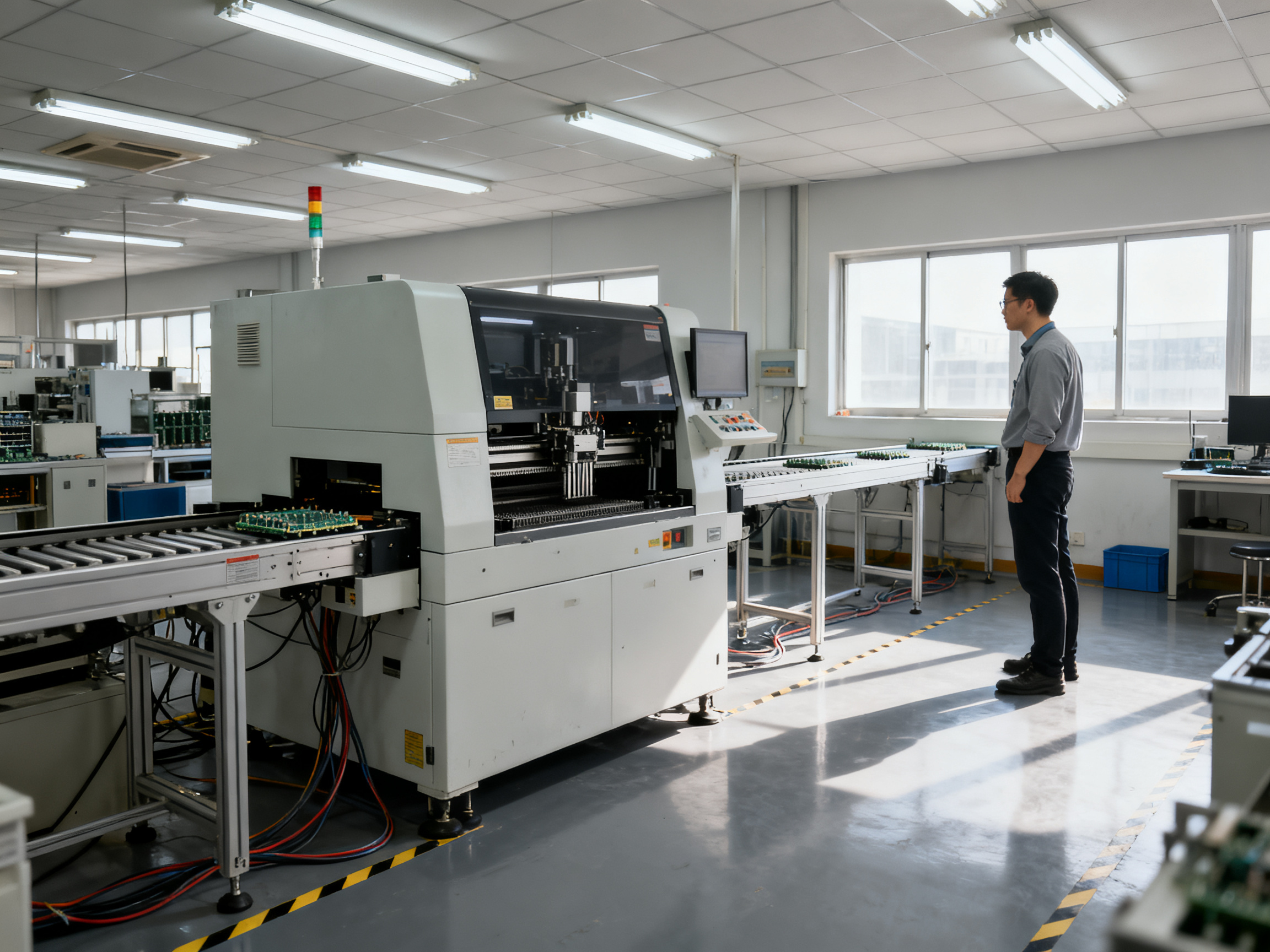
So what exactly is selective soldering? Think of it like using a laser pointer instead of a spotlight. Instead of melting solder across your entire board, a selective soldering machine targets only the specific through-hole pins that need bonding. Everything else stays cool and untouched.
The machine has three main jobs. First, it applies flux only where solder is needed. Second, it preheats that tiny area to the right temperature. Third, a small solder nozzle dips down and delivers molten solder exactly where you want it. The whole board never sees full wave immersion.
This matters big time for mixed-technology assemblies. You know those boards with delicate surface mount parts on top and through-hole connectors on the bottom? Wave soldering would drown those SMD components in heat and cause bridges or outright damage. Selective soldering avoids that problem entirely by treating only what needs treating.
The process works through a programmed nozzle that follows exact coordinates. Modern machines store recipes for each board type, so switching between products takes minutes rather than hours of manual setup. That’s a lifesaver for contract manufacturers handling dozens of different assemblies per week.
Industry adoption shows just how essential this technology has become. About 52% of electronics manufacturers now use selective soldering as their primary through-hole method, and EMS providers alone account for 38.5% of all selective soldering capacity 11 13.
Where this technology shows up in real life:
| Industry | Typical Use Case |
|—|—|
| Automotive | ECU modules, ADAS sensors, battery management systems |
| Industrial | Motor drives, PLC controllers, power supplies |
| Medical | Diagnostic equipment, patient monitoring devices |
| Aerospace | Avionics controls, communication systems |
| Consumer Electronics | Smart home devices, connectivity modules |
These sectors all share something: reliability problems cost way more than the extra precision selective soldering provides. A failed automotive sensor might mean a recalled vehicle. A faulty medical monitor could harm patients. No wonder manufacturers in these spaces treat selective soldering as non-negotiable rather than optional.
The numbers back this up. When comparing defect rates, selective soldering typically achieves 0.5 to 2% defects versus 5 to 12% for traditional wave soldering on complex mixed-technology boards 3. That’s a massive difference when you’re building hundreds of units per shift.
For manufacturers evaluating their options, understanding how the process actually works internally helps with equipment decisions and process optimization. The next sections dig deeper into the mechanics, equipment choices, and techniques that separate good results from great ones.
Understanding the Selective Soldering Process: A Technical Deep Dive
The selective soldering process breaks down into four distinct stages. Each one matters, and skipping steps or rushing through them causes problems downstream. The stages are flux application, preheating, actual soldering, and cooling. Think of it like baking bread. You cannot skip the rising time and expect good results.
Stage 1: Flux Application
Flux comes first. The machine applies it only where solder will eventually go, not across the whole board. This matters because flux does two important jobs. First, it cleans oxides off the metal surfaces. Second, it prevents new oxides from forming while the board heats up.
Modern machines use either drop-jet systems or ultrasonic spray for flux delivery. Drop-jet works great with alcohol-based fluxes and gives you tight control over where the flux lands. Ultrasonic systems can handle more flux types, including water-soluble and high-solids formulas, and they resist clogging better 3.
Stage 2: Preheating
After fluxing comes preheating. The machine warms the board to around 80 to 130 degrees Celsius on the topside. This step activates the flux and gets the board ready for the hot solder. Without proper preheat, you get thermal shock. Components can crack. Joints form poorly.
The preheat ramp rate typically runs about 2 to 4 degrees Celsius per second. Too fast causes splatter and stress. Too slow wastes time and risks drying out the flux. For thicker boards over 3mm with lots of copper, you need more preheat power and longer soak times to get the whole assembly to the right temperature 6 11.
Stage 3: Soldering
Here is where the magic happens. A small solder nozzle dips down and delivers molten solder exactly where needed. For lead-free SAC305 alloy, the solder pot typically runs around 280 to 320 degrees Celsius. Some operators prefer 270 degrees when working in regular air, but 290 degrees works fine when you use nitrogen inerting to control oxidation 10.
The nozzle only touches the target joints. Everything else on the board stays cool. This is why selective soldering works so well for mixed-technology boards that have both surface mount parts and through-hole connectors.
Stage 4: Cooling
After soldering comes controlled cooling. The board exits the heat zone and gradually returns to room temperature. This step solidifies the solder joint properly and limits thermal stress on nearby components. Rushing the cooling causes cracks and weak joints.
Why Parameter Control Matters So Much
Every stage requires tight control. Miss your preheat temperature by 20 degrees and the flux might not activate correctly. Let solder sit too long and you get icicles or bridges. Cool too fast and the joint becomes brittle.
The good news? Modern machines store recipes for each board type. Once you dial in the perfect settings for a product, switching between different boards takes minutes rather than hours of manual adjustment. That repeatability is what makes selective soldering viable for high-mix production environments.
Pro Insight: When selecting solder nozzles, match the nozzle opening to your component spacing. A nozzle that is too wide wastes solder and risks bridging on closely spaced pins. A nozzle that is too narrow might not deliver enough solder for proper hole fill on larger connectors.
Key Components of Selective Soldering Machines
A selective soldering machine is only as good as its core parts. Three components matter most: the solder nozzle, the flux application system, and the preheating setup. Get these right and your process runs smooth. Get them wrong and you’ll be chasing defects all day.
Solder Nozzles
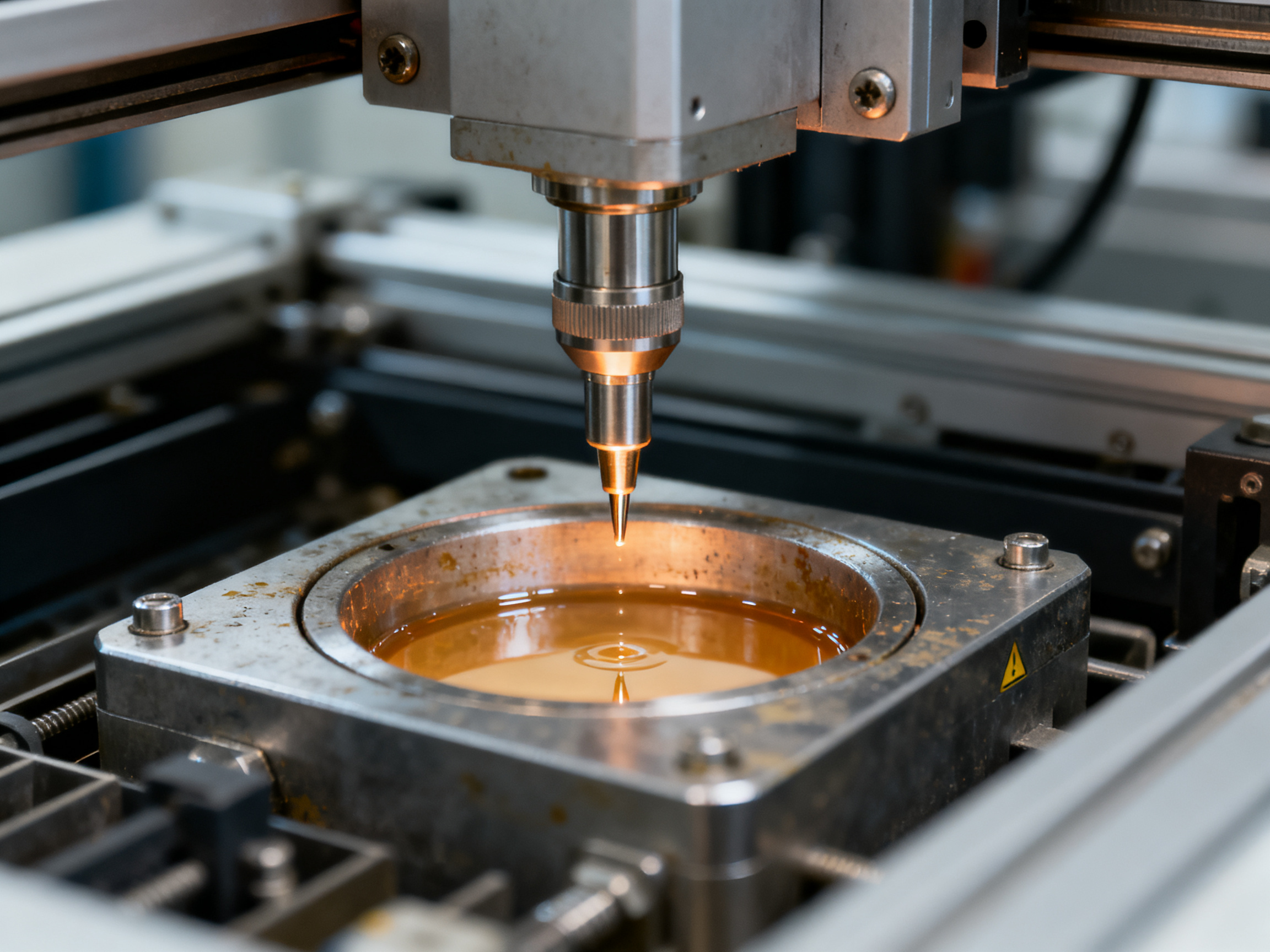
The solder nozzle determines where the molten solder goes. Nozzle geometry comes in three main flavors: mini-wave, drag, and dip. Mini-wave creates a small wave of solder as the nozzle moves. Drag nozzles touch down and trail across a row of pins. Dip nozzles submerse multiple joints at once.
Choosing the right nozzle means matching it to your pad size, component pitch, and what parts sit nearby. A nozzle that’s too wide wastes solder and risks bridging on closely spaced pins. One that’s too narrow might not deliver enough solder for proper hole fill on larger connectors. For lead-free SAC305 alloys, most shops run solder pot temperatures between 280 and 320 degrees Celsius to handle the higher melting point compared to tin-lead 8.
| Nozzle Type | Best For | Typical Use Case |
|—|—|—|
| Mini-wave | Single joints, small groups | Through-hole pins in tight spaces |
| Drag | Rows of pins, connectors | Dual inline packages, headers |
| Dip | Multiple identical joints | Power modules, large connectors |
Flux Application Systems
Flux cleans oxides and preps surfaces for wetting. The machine can apply it through spray, drop-jet, or ultrasonic systems. Drop-jet works great with alcohol-based fluxes and gives tight control over where flux lands. Ultrasonic systems handle more flux types including water-soluble formulas and resist clogging better 3. Ultrasonic fluxing is compatible with all fluxes, including rosin and water-soluble fluxes up to 37% solids, and uses a self-cleaning nozzle to prevent clogging 1.
Pro Insight: When selecting solder nozzles, match the nozzle opening to your component spacing. A nozzle that is too wide wastes solder and risks bridging on closely spaced pins. A nozzle that is too narrow might not deliver enough solder for proper hole fill on larger connectors.
Preheating Systems
Heat matters. Preheating activates the flux and gets the board ready for molten solder. Most systems combine top-side radiant heat with bottom-side convective heat. This combo achieves uniform thermal profiles across the PCB and protects nearby components from thermal shock.
For lead-free processing, preheat typically targets board temperatures around 80 to 130 degrees Celsius. The ramp rate usually sits around 2 to 4 degrees per second. Too fast causes splatter and component stress. Too slow wastes time and risks drying out the flux. Thicker boards over 3 millimeters with heavy copper layers need more preheat power and longer soak times to get the whole assembly to the right temperature 6.
Some manufacturers add nitrogen inerting to the preheat zone. This lowers oxygen below 50 parts per million and reduces oxidation. It can cut dross formation by 40 to 60% and improve wetting on difficult finishes by 15 to 25% 4. The tradeoff is added equipment cost and ongoing gas consumption.
Understanding these three subsystems helps production managers evaluate equipment options based on their specific board types and defect tolerances.
Comparing Selective Soldering Methods: Mini-Wave, Drag, and Dip
Now that you understand the four-stage process, let’s dig into the three main ways machines actually deliver solder. Each method has its own strengths, and picking the right one depends on your board design, production volume, and quality targets.
Mini-wave soldering uses a small fountain of molten solder that rises up to meet the joint. The nozzle stays put while solder pumps through, creating a focused wave. This method shines for single joints or tiny groups of pins, especially when components sit close together and you need precise control over where solder lands. The mini-wave approach gives you tight process windows and minimal heat impact on nearby areas. That’s why it works so well for mixed-technology boards with sensitive SMT parts already placed.
Drag soldering moves either the board or the nozzle along a path, letting solder flow behind as it travels. This technique handles longer pad arrays and connectors nicely. Think dual inline packages, headers, and any component with pins in a row. The motion creates a natural solder trail that fills multiple joints in sequence. It’s less precise than mini-wave but faster when you have several pins to hit.
Dip soldering submerses the target area directly into a solder pot. The board or fixture lowers into molten solder for a set contact time, then pulls back out. This method offers the fastest cycle times when your geometry allows it. One source shows dipping at around 27 seconds versus dragging at nearly 60 seconds for the same task 7. But here’s the catch. Dip soldering has less positional flexibility because you need the nozzle to match your joint pattern exactly. It works best for power modules and large connectors where multiple identical joints need processing at once.
| Method | Best For | Cycle Time | Flexibility |
|—|—|—|—|
| Mini-wave | Single joints, tight spacing, mixed-tech boards | 1-10 minutes depending on joint count | High |
| Drag | Rows of pins, connectors, longer pad arrays | 30-90 seconds | Medium |
| Dip | Multiple identical joints, power modules | 20-40 seconds | Low (tooling-dependent) |
So which method should you pick? A lot depends on your board mix. Mini-wave gives you the most control for complex assemblies. Drag soldering balances speed and precision for standard connector types. Dip soldering wins on throughput when you have high-volume products with matching geometries.
One more thing to consider. Modern machines often let you switch between methods using the same platform. You might run mini-wave for your complex boards and swap to dip tooling for high-volume runs. That flexibility matters when your production mix changes week to week.
From Our Experience: We see a lot of manufacturers start with one method, then add capabilities as their board portfolio grows. A flexible platform lets you adapt without buying separate machines for each approach.
Selective Soldering Advantages and Disadvantages: A Balanced Analysis
Every manufacturing process has trade-offs. Selective soldering is no different. Knowing what it does well and where it struggles helps you decide if it’s the right fit for your production line.
The Upsides: Why Manufacturers Choose Selective Soldering
The biggest win with selective soldering is how it handles heat. Instead of melting solder across your entire board, it targets only the through-hole joints that need it. Everything else stays cool. That means your temperature-sensitive SMD parts never see the kind of heat that damages them.
Defect rates drop significantly too. Selective soldering typically achieves 0.5 to 2% defects compared to 5 to 12% for wave soldering on complex mixed-technology boards. That’s a huge difference when you’re building automotive electronics or medical devices where failures cost more than just rework time.
Joint quality stays consistent across runs. The machine follows the same program every time, so you get repeatable results without operator skill variations. That’s a big deal compared to hand soldering, where your outcomes depend heavily on who is at the bench.
Lead-free compliance gets easier. The process handles lead-free solder profiles without exposing nearby SMD components to damaging temperatures. With RoHS regulations tightening and EU exemptions narrowing in 2026, this matters more than ever for manufacturers serving automotive, industrial, and medical markets.
The Downsides: What to Consider Before Investing
Equipment costs run higher than wave soldering systems. You’re looking at a bigger initial investment, and that can be tough to justify if your volumes are low.
Cycle times for small batches can actually be longer. Setting up programs and fixturing for each board type takes time upfront. So for simple through-hole boards in high volume, wave soldering might still beat selective on throughput.
Precise fixturing and program development matter. Getting the process right for a new board takes engineering effort. You need accurate board references, proper nozzle selection, and thermal profiling. Skip these steps and you’ll chase defects.
Cost-Benefit Analysis Framework
| Factor | Selective Soldering | Hand Soldering | Wave Soldering |
|—|—|—|—|
| Defect rate | 0.5-2% | 5-15% | 5-12% |
| Initial investment | High | Low | Medium |
| Per-board cost (high volume) | Low | High | Low |
| Per-board cost (low volume) | Medium | Medium | High |
| Lead-free compatibility | Excellent | Good | Moderate |
| Operator dependence | Low | High | Medium |
| Changeover time | Minutes | N/A | Hours |
The math gets interesting when you look at real numbers. One 2026 cost analysis showed selective soldering hitting payback in about 11.5 months when labor, rework, and material savings all factored together. Vendors typically cite 9 to 18 months for mid-volume lines processing 200 to 500 boards per shift.
Expert Tip: Common inspection pitfalls in high-volume production include missing insufficient fill on hidden joints and overlooking flux residue near connectors. Use AOI for visible joints and X-ray for hidden solder to catch defects before they ship.
So when does selective soldering make sense? It’s worth the investment for mixed-technology boards with both SMD and through-hole parts, high-reliability products where defects are costly, lead-free assemblies that need tight thermal control, and production runs where changeover flexibility matters.
For simple through-hole boards in very high volume with straightforward geometry? Wave soldering probably still wins on cost per board. The key is matching the process to your actual product mix rather than assuming one size fits all.
Selective Soldering vs. Hand Soldering vs. Wave Soldering: Making the Right Choice
So how do you actually pick between these three approaches? Here’s the deal. Each method has its place, and the right choice depends on what you’re building, how much you’re building, and what happens when a joint goes bad.
Hand soldering gives you total flexibility. You can touch up prototypes, fix individual joints, and work on boards with weird geometries that no machine could handle. Sounds perfect, right? But here’s the catch. Results vary based on who is holding the iron. An experienced technician might hit 98% first-pass yield, while someone less practiced drops that number significantly. Labor costs also scale directly with production volume. For high-mix contract manufacturers running hundreds of different board types per month, relying on hand soldering for through-hole work becomes a bottleneck and an expense that eats into margins fast.
Traditional wave soldering handles high-volume through-hole assemblies efficiently. The board moves over a molten solder wave and every joint on the bottom gets soldered in one pass. It’s fast and cost-effective for simple boards. But wave soldering treats your entire assembly like one big target. If you have surface mount parts on top, they see all that heat and solder splash. Mixed-technology boards often fail wave soldering because the SMD components get damaged or drowned in solder bridges. You’re forced to mask off areas, which takes time and still might not prevent defects.
Selective soldering sits in the middle ground. It gives you automated consistency and repeatability, but with surgical precision that wave soldering cannot match. You program exactly which joints get soldered, the machine follows that program every single time, and nothing else on the board gets touched. For mixed-technology assemblies, this is exactly what you need. The tradeoff is higher equipment cost and slightly longer cycle times for some applications.
| Factor | Hand Soldering | Wave Soldering | Selective Soldering |
|—|—|—|—|
| Defect rate | 5-15% | 5-12% | 0.5-2% |
| Best for | Prototypes, low volume, rework | High volume, simple THT boards | Mixed-tech, high reliability |
| Labor intensity | High | Low | Low |
| Changeover time | None | Hours (masking) | Minutes (program switch) |
| Equipment cost | $500-$2,000 | $30,000-$80,000 | $80,000-$200,000 |
| Lead-free handling | Manual skill dependent | Challenging | Designed for it |
The numbers tell a clear story. When defect rates drop from 5-12% down to 0.5-2%, the math changes fast. Rework costs money. Returns cost more. In industries like automotive and medical devices, a single field failure can dwarf the cost of the entire assembly. That’s why so many manufacturers in 2026 are choosing selective soldering even when the equipment costs more upfront.
So when should you pick which method?
Go hand soldering if you’re building fewer than 50 boards per month, you need maximum flexibility for one-off designs, or you’re doing prototype work that might change tomorrow.
Go wave soldering if you have high-volume, simple through-hole boards with no sensitive surface mount parts on the opposite side. The throughput is hard to beat when your geometry allows it.
Go selective soldering if you’re building mixed-technology assemblies, you need lead-free compliance, your products carry reliability requirements, or your production mix changes frequently and changeover time matters.
Most established SMT lines in 2026 run both wave and selective systems. Wave handles the easy bulk work. Selective handles everything else. It’s not about finding one method to rule them all. It’s about matching the right tool to each job.
Best Practices for Selective Soldering Quality Assurance
Here’s where things get real. You’ve got your selective soldering process dialed in, but how do you know it’s staying that way? Quality assurance isn’t a one-time setup. It’s an ongoing commitment to catching problems before they become costly escapes.
The first step is establishing statistical baselines for your critical parameters. Think solder temperature, contact time, flux quantity, and preheat temperatures. Without these baselines, you’re flying blind. Most shops run solder pots between 280 and 320 degrees Celsius for lead-free SAC305 alloys, with tighter control giving you better repeatability 8. Document your actual readings across multiple runs to build a real picture of what “normal” looks like for your process.
Inspection That Actually Catches Problems
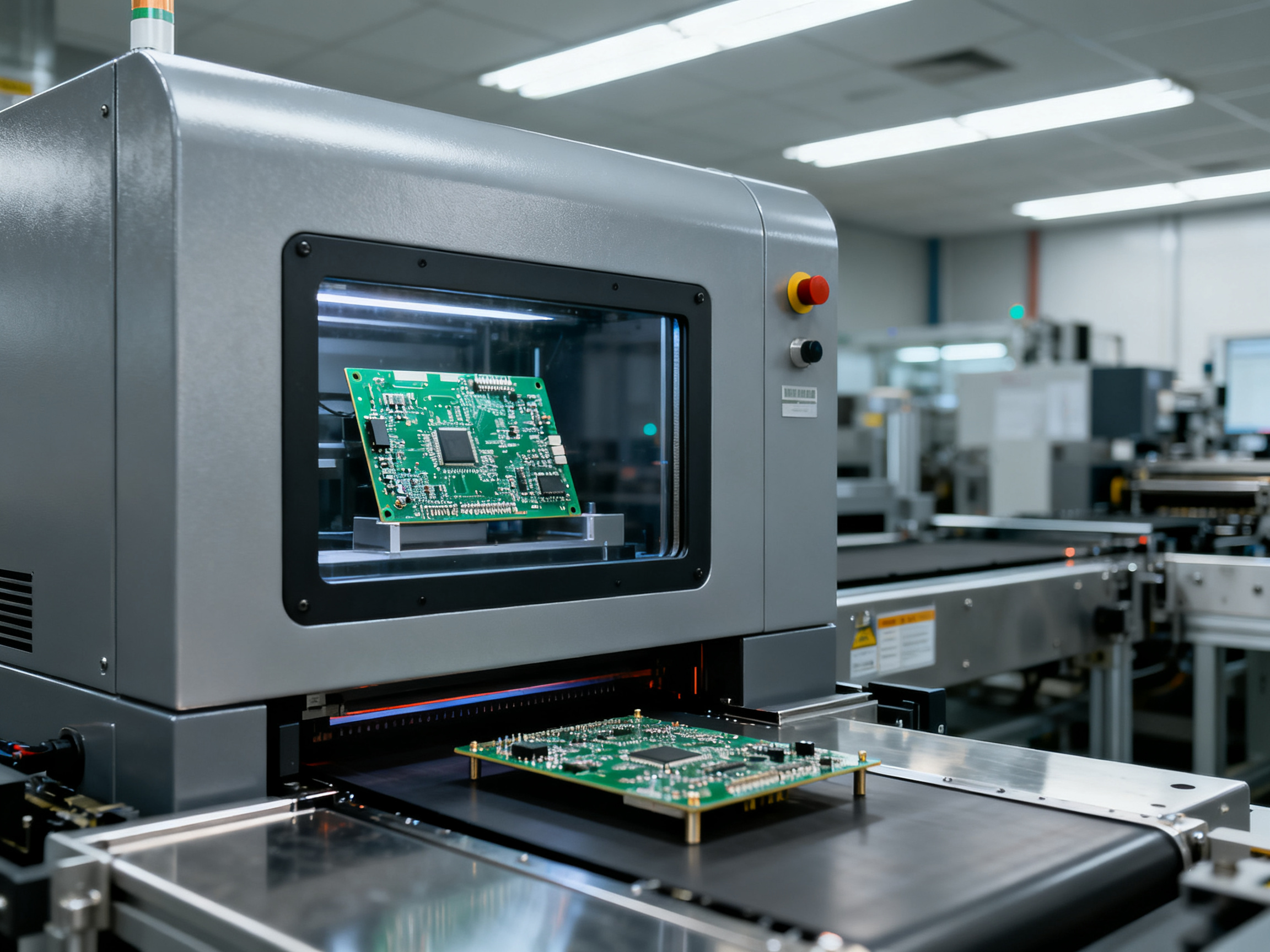
Visual inspection works great for surface defects like bridges, icicles, and fillet issues. But here’s the catch. Some joints hide where your eyes can’t reach. That’s where X-ray inspection comes in. It lets you check voiding and hole fill inside buried connections without destroying the board. For boards with BGA or QFN components nearby, X-ray becomes essential rather than optional.
Common defect types to watch for:
- Solder bridges between adjacent pins
- Icicles and spikes from excessive contact time
- Insufficient hole fill leaving weak joints
- Pad lifting from thermal stress or improper support
- Flux residue causing reliability issues over time
Expert Tip: Common inspection pitfalls in high-volume production include missing insufficient fill on hidden joints and overlooking flux residue near connectors. Use AOI for visible joints and X-ray for hidden solder to catch defects before they ship.
Keeping Track With SPC
Statistical Process Control sounds fancy, but the idea is simple. Log your key parameters every cycle. Watch for trends before they turn into escapes. If your solder pot keeps drifting upward, you catch it on Tuesday instead of finding bridges on Friday.
The parameters worth tracking include solder bath temperature, contact time, flux deposition rate, and preheat ramp rate. Set control limits based on your actual process capability, not textbook numbers. Your boards, your data, your limits.
Quality Checklist for Selective Soldering Operations
Use this checklist for each production run:
| Checkpoint | What to Verify |
|—|—|
| Setup verification | Correct program loaded, proper fixturing in place |
| Temperature log | Solder pot within specification, preheat reaching target |
| Flux check | Correct type loaded, spray pattern clean |
| First article | Visual inspection of sample joints, X-ray if required |
| In-process monitoring | Periodic sampling based on volume and defect history |
| Defect tracking | Log all defects by type and location for Pareto analysis |
This systematic approach keeps defects from escaping to customers and eating into your margins.
Implementing Selective Soldering in Your SMT Production Line
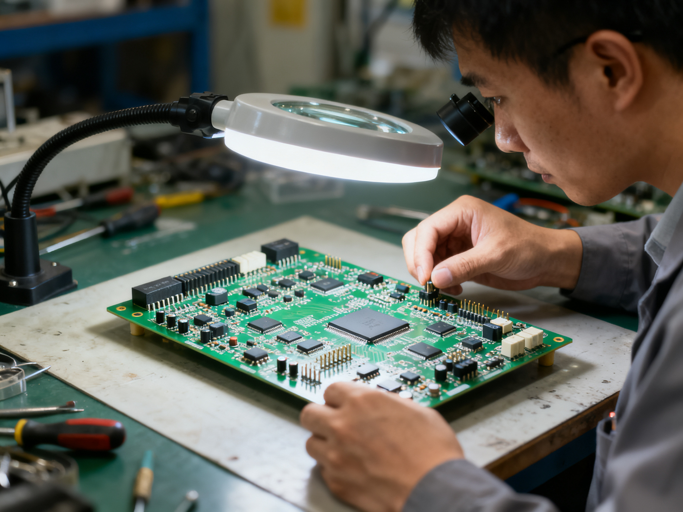
So you have decided selective soldering makes sense for your operation. Now what? Implementation is where a lot of projects stumble, not because the technology is hard, but because people underestimate the prep work needed before the machine even arrives.
Phase 1: Equipment Evaluation
Start by matching your board characteristics to equipment capabilities. Ask yourself a few basic questions. How many through-hole joints per board on average? What is the minimum pad spacing you need to solder without bridging? Do you have components on the bottom side that sit close to your through-hole pins? These answers determine whether you need high-position nozzles, extra clearance tooling, or dual-station capability.
Most manufacturers in 2026 offer platforms with modular solder pots, configurable flux systems, and recipe storage for hundreds of board types. If your product mix changes weekly, prioritize fast changeover and offline programming over raw speed. That flexibility pays off faster than an extra second per board.
Phase 2: Process Development
Fixture design usually takes longer than expected. Your board needs proper support underneath to prevent flexing during soldering, and you need accurate referencing so the nozzle hits the right holes every time. We see shops budget two to four weeks for first article qualification on a new board family, though simpler assemblies might come in faster.
Program development follows fixture setup. You will dial in preheat profiles, flux delivery rates, solder temperature, and contact time for each board type. Keep detailed records. These recipes become your process library, and switching between products should take minutes once you have them stored.
Phase 3: Production Integration
Connecting your selective soldering system to MES and ERP platforms matters more every year, especially for automotive and aerospace customers who require full traceability. Modern machines support standard network interfaces that log board serial numbers, process parameters, and inspection results for each run.
Implementation Checklist
Use this checklist to track your progress:
| Phase | Key Tasks | Typical Duration |
|—|—|—|
| Equipment evaluation | Define board specs, joint density, clearance requirements | 1-2 weeks |
| Fixture design | Build tooling, verify board support and referencing | 2-4 weeks |
| Program development | Thermal profiling, parameter optimization, first article inspection | 2-4 weeks per board family |
| MES/ERP integration | Network setup, traceability configuration, data validation | 1-3 weeks |
| Operator training | Machine operation, maintenance, basic troubleshooting | 1-2 weeks |
Building Your Internal Capability
The best selective soldering operations have someone on staff who owns the process. This person understands thermal profiling, knows how to read defect patterns, and can adjust recipes without waiting for vendor support. Cross-functional teams work well here, bringing together manufacturing engineering, quality, and the operators who run the equipment daily.
Training programs through SMTA and IPC-aligned certifications give your team a solid foundation. But nothing replaces hands-on experience with your actual board types. Build time for supervised trials before expecting independent operation.
From Our Experience: We have seen manufacturers skip process documentation and pay for it later when operators leave or equipment moves to a different shift. Lock down your recipes, document your setup verification steps, and treat change control seriously from day one.
The upfront investment in proper implementation pays back through faster changeovers, fewer defects, and confidence that your process will perform consistently no matter who is running the machine.## Future-Proofing Your Selective Soldering Operations
The electronics industry keeps moving fast. If you’re running selective soldering today, you need to think about what comes next. Here’s where things are heading in 2026 and beyond.
AI-Assisted Process Optimization
AI is starting to show up in selective soldering equipment, but it’s not quite the full autopilot some vendors advertise. Right now, the real value is in monitoring and analytics, not autonomous control. Think of it as having a smart assistant that watches your process parameters and flags issues before they become defects.
The machine logs everything: solder temperature, contact time, flux application, preheat data. Then software looks for patterns. If your solder pot temperature keeps drifting upward over several shifts, AI spots the trend on Tuesday instead of finding bridges on Friday when you’re doing final inspection.
This is useful because it helps you move from reactive problem-solving to proactive process control. You’re not waiting for defects to appear; you’re seeing the conditions that lead to defects. But here’s the honest answer: fully self-optimizing soldering systems that adjust themselves without human oversight? That’s still more promise than proven reality in most factories.
Industry 4.0 Integration
Being connected matters more every year. Your selective soldering machine should play nice with your MES and ERP systems. Board serial numbers, process parameters, inspection results – all that data should flow automatically. This isn’t just about convenience. It’s about traceability. When a customer comes asking about a batch from six months ago, you need to show exactly what happened at every step.
Remote monitoring is another piece of this. If something goes wrong at 2am, you want to know about it before your operator arrives for the morning shift. Modern machines support this through standard network interfaces. You get alerts, maintenance reminders, and process data dashboards without needing someone standing right at the machine.
Predictive maintenance is the buzzword here. The idea is simple: track wear on components like solder nozzles and pumps, then schedule maintenance before failures happen. Some systems already log motor current and flux flow to catch problems early. The numbers vary by vendor, but the goal is the same. Reduce unexpected downtime. Keep your line running.
Enhanced Nitrogen Inerting Systems
Nitrogen inerting is getting smarter and more efficient. Newer systems use localized shrouding instead of flooding the whole chamber with gas. This cuts your nitrogen consumption significantly while still getting the oxidation control you need. Less dross, better wetting, fewer bridges. That’s the promise.
Real-world results vary depending on your board finishes and flux choices, but the direction is clear. One source says dross formation drops by 40 to 60 percent with better inerting. Wetting improves on tough finishes too. Worth it? Depends on your defect history and your budget.
Smaller Nozzle Geometries
Component miniaturization keeps pushing boundaries. As pitches get tighter, nozzle manufacturers are responding with smaller, more specialized geometries. These let you access joints in denser areas without disturbing nearby components.
But here’s the catch: selective soldering is still fundamentally a through-hole and selective-access process. If you’re dealing with 0.3mm pitch or finer, you’re probably looking at reflow or laser-based methods instead. Selective soldering shines at through-hole work and mixed-technology assemblies. Know where your equipment fits and don’t expect it to do jobs it wasn’t designed for.
What This Means for Your Equipment Decisions
When you’re evaluating new systems, think about connectivity first. Can the machine log everything you might need for traceability? Does it work with your existing MES? Can you monitor it remotely? These features matter more as customers demand more documentation and as your own quality systems mature.
Nitrogen capability is worth considering if you’re running lead-free alloys or dealing with oxidation issues. And think about your board roadmap. If you’re expecting more mixed-technology assemblies or tighter tolerances, a flexible platform with good nozzle options makes more sense than a bare-bones unit.
From Our Experience: We’ve seen manufacturers skip process documentation and change control early on, then pay for it later when key operators leave or equipment moves to different shifts. Lock down your recipes, document your setup verification steps, and treat change control seriously from day one. The machines last longer than the people who run them.
The future of selective soldering is about smarter processes, better data, and tighter integration with factory systems. Focus on what’s proven today, but keep an eye on where the technology is heading. Your equipment choices now should set you up for the next several years, not just the next product launch.
Conclusion: Your Path to Optimized Selective Soldering Performance
Selective soldering has earned its place as an essential technology for manufacturers building mixed-technology assemblies. The numbers tell the story. When defect rates drop from 5 to 12 percent down to 0.5 to 2 percent, the math changes fast, especially for automotive, medical, and industrial products where failures cost more than just rework time.
The real question is not whether selective soldering makes sense for your operation. It probably does if you are working with boards that combine surface mount and through-hole parts. The question is how to implement it well.
Investment decisions need to balance what you need today against where your production is heading. A flexible platform that handles recipe changes quickly matters more than raw speed if your product mix shifts week to week. Think about connectivity too. MES integration and traceability data flow matter more every year as customers demand documentation.
Success comes from treating selective soldering as a system, not just a machine. Process parameters, quality inspection, operator training, and ongoing optimization all work together. Skip one piece and the whole thing suffers.
Key Takeaways and Next Steps by Adoption Stage
| Your Situation | Recommended Next Steps |
|—|—|
| Just starting out | Pilot with your worst-case board, validate thermal profiles, build recipes before production runs |
| Adding selective to existing line | Focus on MES connectivity, operator training, and defect tracking from day one |
| Optimizing current operation | Run SPC on critical parameters, audit inspection coverage, consider nitrogen inerting for lead-free work |
Start with your hardest board. Get that process locked down. Then expand from there.
Selective soldering continues to evolve with smarter monitoring, better nitrogen control, and more connected factory integration. The manufacturers who invest in proper process development now will be ready for whatever comes next.