
Published: November 15, 2026
Last updated: November 15, 2026
Reading Time: 17 minutes
Reviewer: [Placeholder, no reviewer assigned yet]
This guide covers SMT conveyor selection in 2026: belt conveyor types, SMT cooling conveyor options, inline SMT PCB conveyor links, and PCB turn conveyor mechanics, plus a selection framework you can use when writing an RFQ.
Published: November 15, 2026
Last updated: November 15, 2026
Reading Time: 17 minutes
Reviewer: [Placeholder, no reviewer assigned yet]
Here’s the thing about SMT lines that nobody warns you about: the placement machine gets the credit, but the conveyor decides whether you actually ship that day.
A board arrives at the reflow oven slightly wider than the rail gap. It shunts sideways, lands on a stopper, and now the oven is blocked with 40 minutes of takt time still on the clock. Same story with a board that exits reflow too hot and gets handled by a gloved hand, or a buffering link that starves because the handoff signal arrives a few hundred milliseconds late. None of that shows up in the placement machine’s spec sheet.
So let’s break it down. Four conveyor families cover most lines in 2026: standard belt units, also called an smt conveyor belt; dedicated smt cooling conveyor sections after reflow or wave soldering; inline smt pcb conveyor links that sit between printers, placement machines, and inspection equipment; and the pcb turn conveyor, whether that’s a 90 degree corner, a 180 degree flip, or a turntable.
Each one solves a different problem, and picking the wrong type creates the bottleneck you were trying to remove.
The flow looks simple on paper:
Printer  >  Placement  >  Reflow / Wave Solder  >  Cooling  >  AOI / Inspection
             ^                                                          |
             |---------------  inline buffering / accumulation  --------|
Every arrow is a handoff. Every handoff is a chance for a board to tilt, stick, overheat, or wait.
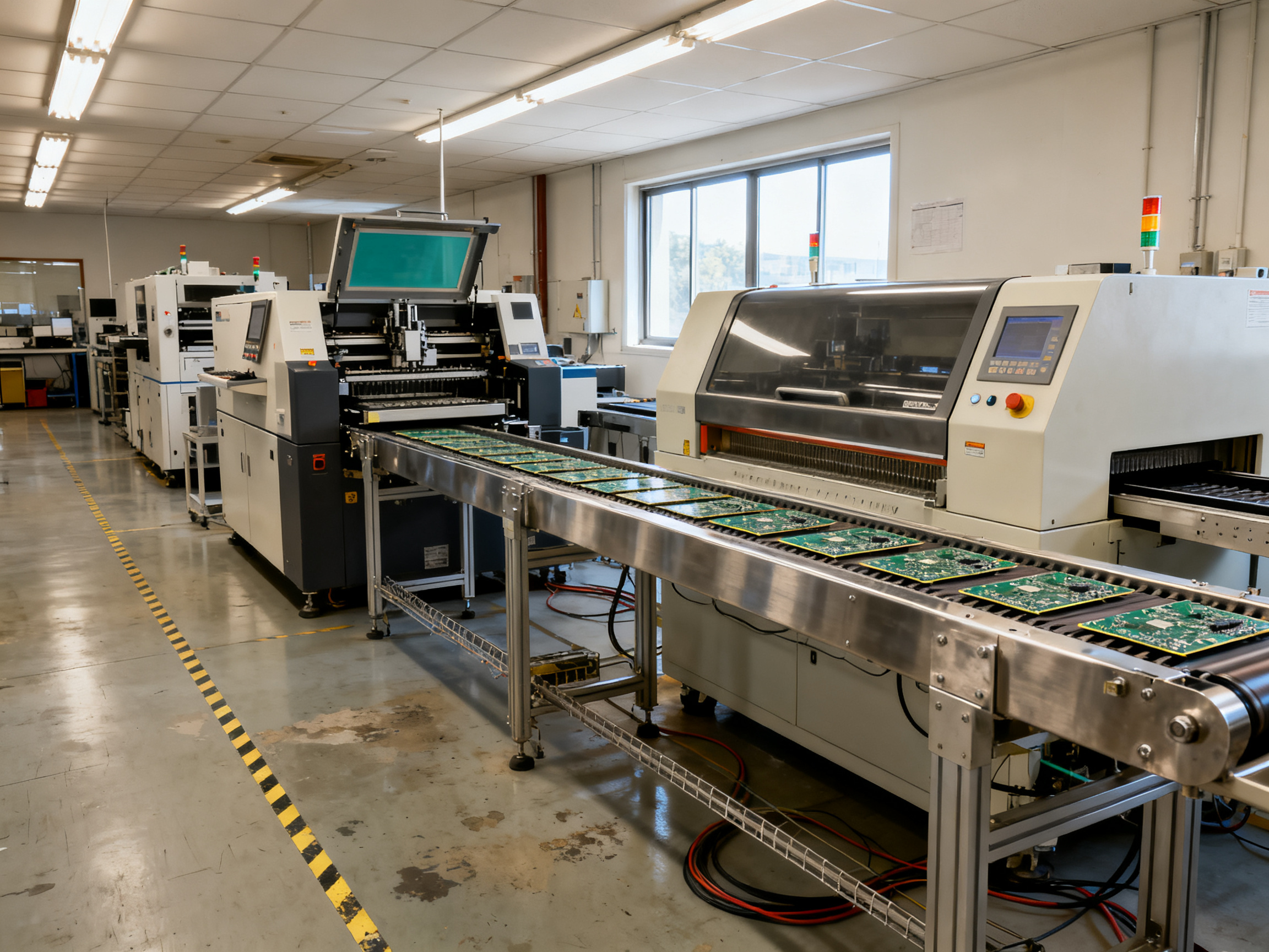
This guide breaks down how each conveyor type works mechanically, what each one is genuinely good at, and how to match the right unit to your process. It’s written for production heads, process engineers, procurement managers, and technical officers evaluating a new line or planning an upgrade in 2026.
Note: this guide is still awaiting a named author and a technical reviewer. Verified author credentials, reviewer assignments, and source-level citations will be added once they are supplied, and the article will not carry unverified figures in the meantime.
Introduction: Why Conveyor Selection Affects the Entire SMT Line
About the Author
[Author Name] is [verified role or credential] with experience in [verified SMT, PCB handling, soldering, automation, or electronics-manufacturing work]. [He/She/They] has contributed to [verified relevant project or measurable achievement], which shapes the process-first approach used throughout this conveyor selection guide.
Editorial status: This guide is published ahead of its named author and technical reviewer assignment. Verified author credentials, reviewer attribution, and source-level citations will be added once supplied. Until then, no unverified specifications, temperatures, or performance figures appear in this article.## 2. Belt Conveyor Systems and SMT Conveyor Options
Once the board is supported and aligned, something has to move it. In most SMT lines, that something is a belt. The belt may look simple, but its material, width, tension, and drive arrangement can determine whether panels move smoothly, stop accurately, and survive the heat of the reflow oven.
A belt conveyor uses a continuous loop of flexible material running around pulleys. One or more motors turn the pulleys, creating friction that carries the board forward. The board typically rides on two rails or on the belt itself, depending on the machine design. Small sensors detect its leading and trailing edges, while a stopper, gate, or motor-controlled motion profile controls where it stops.
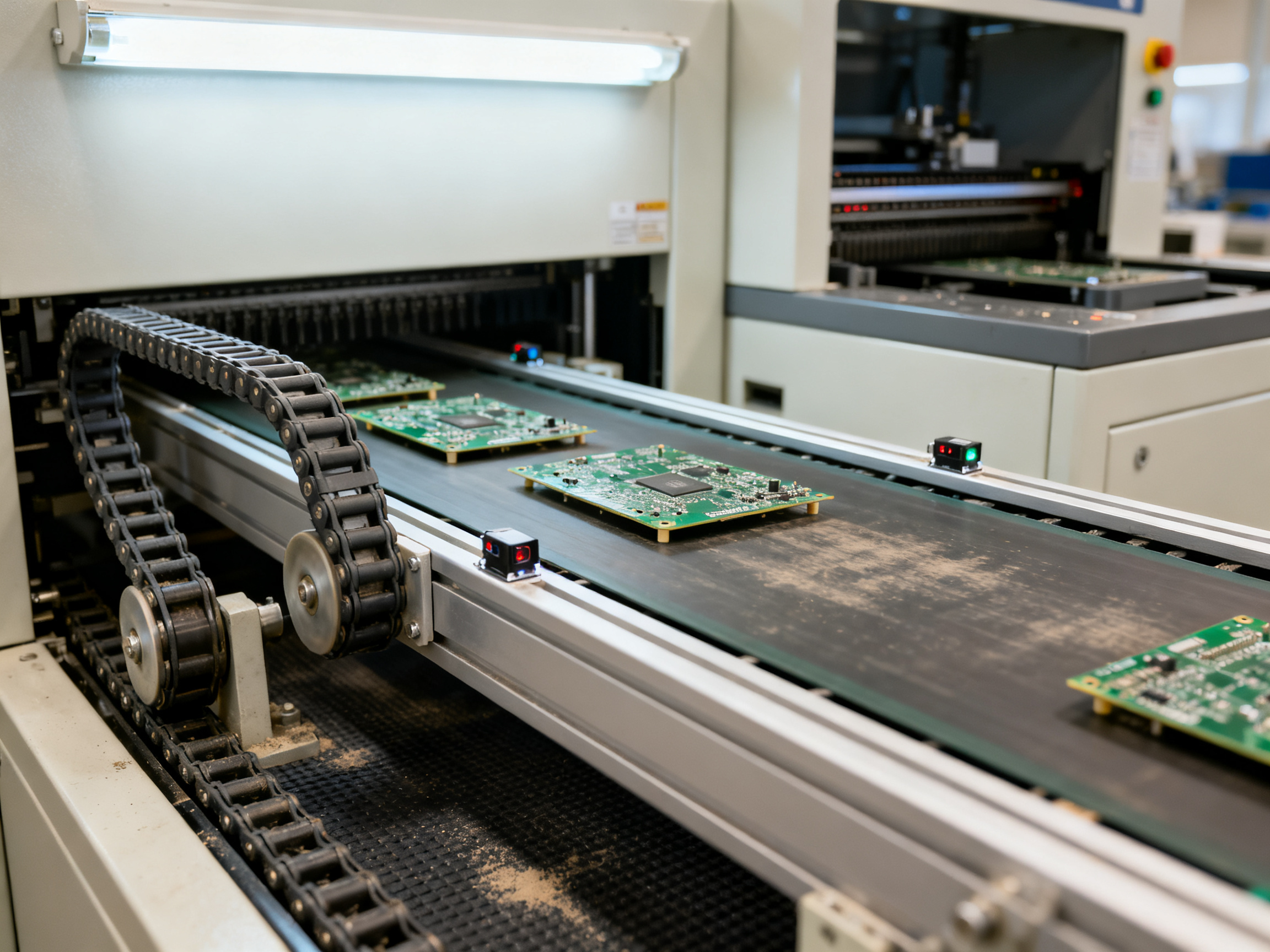
The most common SMT conveyor belt options include:
| Belt option | Typical characteristics | Best suited to |
| — | — | — |
| Standard rubber belt | Durable, economical, and widely available | General-purpose assembly lines and moderate-temperature environments |
| Silicone belt | Flexible, resistant to heat, and less likely to mark components | Reflow ovens, inspection stations, and clean handling |
| PTFE-coated belt | Low-friction surface with strong temperature resistance | High-temperature processes and applications requiring easy cleaning |
| Plastic link belt | Modular links travel around the drive system | Heavy panels, washdown environments, and lines needing longer conveyor sections |
| Finger conveyor | Individually driven fingers move each board | Dipped or bottom-board assemblies, inspection, and selective buffering |
| Cable conveyor | A flexible cable carries boards through a curve or along a track | Compact systems and routes with tighter space constraints |
Belt material matters more than it appears
The belt is exposed to more than the board’s weight. It rubs against panel edges, collects solder dust, oil, flux residue, and packaging debris. It may also enter an oven or operate near hot equipment. A belt that is too soft can wrinkle or allow a board to drift. A belt that is too rigid can mark components or create transfer problems.
Temperature is usually the first concern in reflow lines. The belt and its supporting track must tolerate the oven profile without stretching, hardening, or leaving residue on the underside of a PCB. A material that performs well in a cool assembly area may fail after several hours inside a high-temperature zone, so the full temperature range matters—not just the maximum operating temperature.
The surface texture matters too. A smooth, low-friction belt makes positioning easier, while a textured or cleated surface can provide traction for awkward loads. The right choice depends on the board, the rail arrangement, the transfer method, and the required stopping accuracy.
Width, tension, and tracking
Three mechanical details are easy to overlook:
- Width: The belt must be long enough to support the intended panel family without letting the board tip or hang over the edge.
- Tension: Too little tension causes slipping and inaccurate stops; too much tension increases bearing wear and can pull the conveyor out of alignment.
- Tracking: The belt must remain centered as it runs. Edge wear or uneven tension can cause it to wander toward one rail, reducing usable support and creating jams.
Rather than selecting a belt from its catalog description alone, operators should run representative panels at the line’s actual speed and temperature. Observe how the board enters, stops, and leaves each station. A belt that handles a small, light board but twists under a large panel is not suitable for that production family.
Expert Tip: Keep spare belts matched to the exact conveyor model, width, and material grade. During a line stoppage, a generic replacement can introduce changes in drag, positioning, and heat resistance that create hours of troubleshooting.
Belt conveyors, buffer conveyors, and indexing
Not every conveyor simply runs continuously. A buffer conveyor holds additional boards so the upstream printer can keep working while a slower downstream process catches up. A fingertip conveyor uses independently controlled fingers to separate boards and place them into the next machine. A stop-and-inspect conveyor accelerates, decelerates, and stops each panel at a camera or operator station.
These modes affect the relationship between machine cycle time and conveyor speed. Continuous motion is fast and simple, but it offers little tolerance for a downstream pause. Stop-and-inspect systems improve control and reduce board-to-board contact, but they require more precise motion and handoff logic. Buffering improves throughput when cycle times differ, yet it consumes space and adds another point where board alignment can go wrong.
The practical question is not simply, “Which belt is fastest?” It is, “Which conveyor architecture matches the product, process, and required throughput?” A line carrying mixed-size panels may need adjustable rails and programmable buffering. A line with one stable board size may perform better with a simpler stop-and-go conveyor.
In the next section, we’ll compare the major conveyor types side by side—belt, roller, chain, and magnetic—and look at how to select the right system for a specific SMT production line.## 2. Belt Conveyors and SMT Conveyor Belts
A belt conveyor does one job quietly: it moves a board from station to station without shaking it, scraping it, or dropping it. That sounds simple. In practice, the belt is the part of an SMT line that touches every single panel, and it is the first thing that decides whether a board survives the trip from printer to AOI.
How the belt actually works
A continuous loop of flexible material runs around drive pulleys. Motors turn the pulleys, friction carries the loop forward, and the board rides on the belt or on a pair of support rails. Edge sensors detect the leading and trailing edges of each panel, and a stopper, gate, or controlled motion profile decides where it stops. In most SMT conveyor systems, that stop signal is what syncs the conveyor to the printer, placement machine, and inspection equipment.
Belt material comparison
| Belt option | What it handles well | Watch out for |
| — | — | — |
| Standard rubber belt | Cost, durability, wide availability | Marking soft parts, less heat tolerance |
| Silicone belt | Heat, flex, clean component handling | Higher cost, picks up dust if it sheds |
| PTFE-coated belt | Temperature resistance, easy cleaning | Cost, and a slick surface needs good grip |
| Plastic link belt | Heavy panels, washdown, long runs | Joints can bump delicate edges |
| Finger conveyor | Separating and indexing boards | More moving parts to maintain |
| Cable conveyor | Curves and tight routing | Less support for heavy or wide panels |
Antistatic properties matter here too. A belt that is not rated for controlled ESD handling can put charge on the panel and on the components sitting on it, and that charge shows up later as a mysterious failure in test, not on the line.
Rail adjustment, speed, and board support
Rails usually adjust sideways to match panel width, and that adjustment is the fix for most side-shunt jams. But rails set too narrow twist the panel, and rails set too wide let it rattle. Speed control matters for a different reason: if the conveyor runs faster than the placement machine’s cycle, boards queue; if it runs slower, the placement machine starves.
Expert Tip: Before you buy, put a worst-case board on the line. The widest panel, the heaviest, the one with the tallest components, and the one with the least edge clearance. Watch how each one enters, stops, and leaves. A belt that handles a small light board cleanly can still twist a heavy panel or mark a tall component.
Best fit, and where belts stop making sense
Belt conveyors suit controlled, low-vibration transport between printers, placement machines, soldering systems, AOI, and unloading. They struggle in oily or dirty environments, with hot boards handled immediately, with very heavy panels, and with densely populated high-density boards where clearance under the belt is tight.
Maintenance is boring and predictable. Clean the belt, check tracking and tension, keep sensors clean, and confirm the rails are parallel.
For high-volume lines running lead-free reflow and wave soldering, a matched belt conveyor setup from a supplier that builds the full SMT production line, such as S&M Co. Ltd. (Shenzhen Chuxin Electronic Equipment Co., Ltd.), tends to integrate more cleanly with the oven’s own transfer conventions.
In the next section, we’ll compare belt, roller, chain, and magnetic conveyors side by side and pick a system for a specific SMT production line.## 3. SMT Cooling Conveyors After Reflow or Wave Soldering
A board leaving a reflow oven is not “done.” It’s still hot, still moving, and still full of molten solder that is on its way to freezing. What happens in the 30 seconds after the oven decides the same way that happens with any PCB handling equipment: whoever touches the board next decides whether it gets inspected cleanly or warped.
That’s the job of an SMT cooling conveyor: controlled transport that brings board and component temperatures down toward a safe handling point before a human hand, an AOI camera, a packaging tray, or an automated handler arrives.
When passive transport stops being enough
Cooling happens on the board’s own timeline, and it isn’t linear. The core stays hot longer than the surface. A panel that looks fine on top can still be holding heat in its center layers, which is exactly where warpage and thermal-shock risk live.
Cooling configurations you’ll see in 2026:
| Configuration | How it cools | Watch for |
| — | — | — |
| Passive transport (ambient) | Convection and radiation only, no forced air | Slowest option; length becomes the only variable |
| Fan-assisted | Gentle airflow across the panel surface | Uniformity varies; needs clear airflow path |
| Forced-air / directional | Focused jets at board or component zones | Better for dense or heavy panels, but can shift light boards |
| Controlled cooling with monitoring | Active airflow with sensors or recipe control | Highest cost, best traceability |
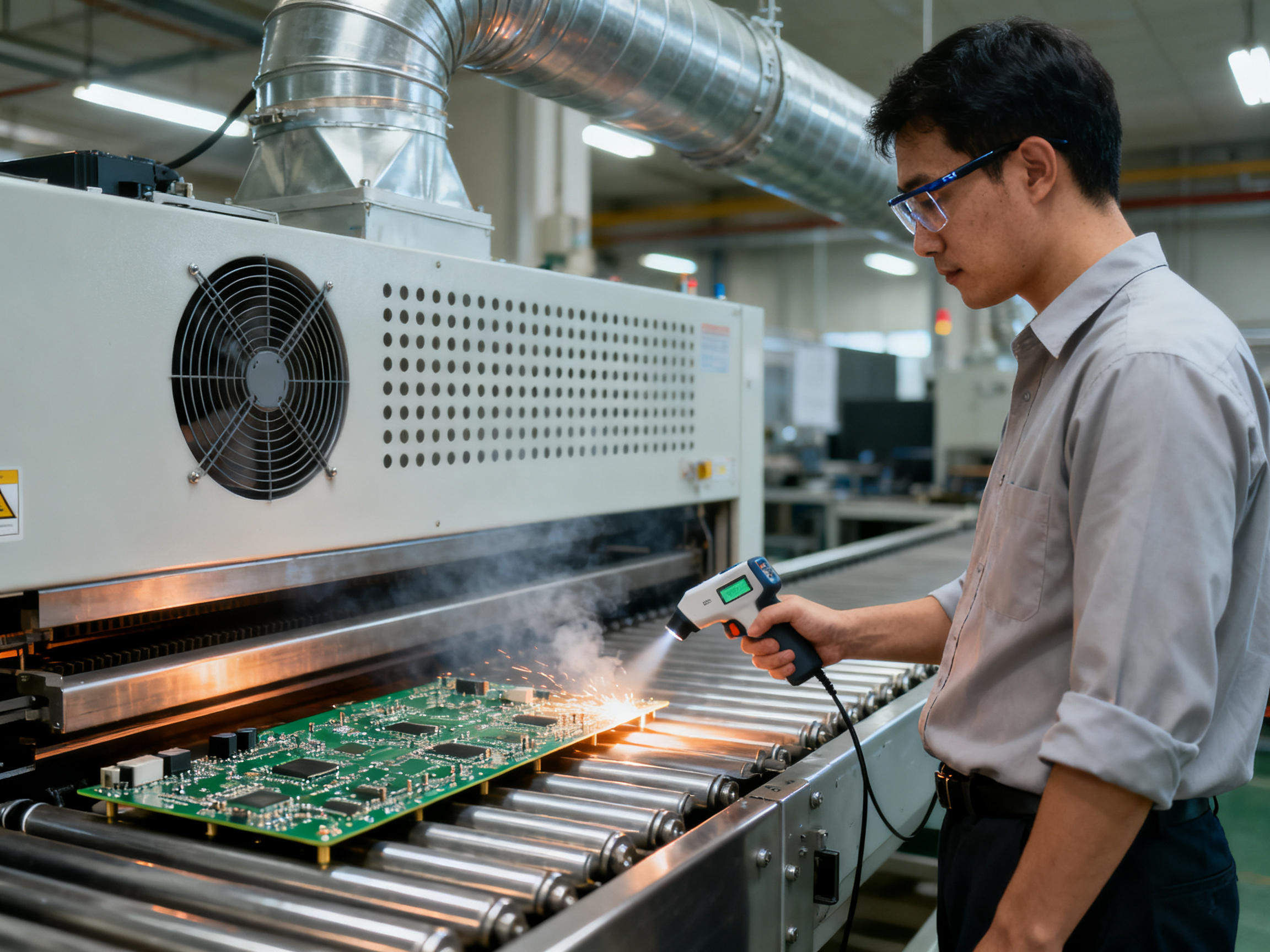
Because no single exit temperature fits every product, vendors quote cooling capacity differently: length in millimeters, airflow in cubic meters per hour, watts per zone, or boards per hour. Read any of those as a vendor-specific number, not a universal spec.
A simple cooling-load example
Let’s walk through one board to show the method, since every number here is an assumption you replace with your own.
Assume a 250 mm by 200 mm panel, 1.6 mm FR-4, roughly 300 g of mass. Copper and components add to the effective heat capacity, so treat the 300 g as a floor, not a final figure. If that panel exits the oven 60 K above ambient, and you assume roughly 350 J/kg·K for the panel, the energy to remove is about 6,300 joules. At 1,000 joules per second, that is a shade over 6 seconds of net heat removal. Real systems run less efficiently than that, so the practical answer is longer, and it gets longer as board mass and layer count climb.
That calculation is really just a conversation starter with the supplier. Their job is to show you a conveyor length that clears your real exit temperature with margin.
The risks nobody puts in the brochure
- Thermal shock: Pulling a panel into cool air too fast can stress solder joints and large copper planes.
- Uneven cooling: A thin top layer cooling while the core lags creates differential contraction and warpage.
- Flux fumes: Cooling airflow can pull volatile residue and smoke toward operators. Filtration is not a luxury.
- Condensation: Humid shop air plus a cold board equals moisture on the surface, which is bad news for adhesion and for coating inspection.
- Operator exposure: A line that requires a glove or a heat barrier at the exit is a line that will eventually have a handling defect.
Pro Insight: Validate cooling capacity with actual board-temperature measurements, not just oven recipes and conveyor length. Oven profiles describe what the board saw on the way in. A thermocouple or thermal camera on the actual panel at the exit tells you what the board is carrying when it reaches the operator.
Cooling capacity should be measured at the board, on your product, at your line speed. A conveyor that cools a small, light panel beautifully may do nothing for a heavy, multilayered assembly moving at full takt.
Once the board is at a stable temperature, the rest of the line can be sized on takt rather than on guesswork. That’s the next section: inline SMT PCB conveyor links, and how buffering capacity changes when cycle times don’t match.## 4. Inline SMT PCB Conveyors for Linking and Buffering Equipment
The printer doesn’t feed the placement machine directly. Something sits between them, and that something is an inline SMT PCB conveyor. It sounds like plumbing. It is actually where cycle time gets balanced, where WIP is created, and where a jam in one machine stops one machine instead of the whole line.
The family of inline equipment
Not all inline conveyors do the same job, and mixing them up is a classic spec mistake.
| Inline unit | Core purpose |
| — | — |
| Linking conveyor | Carries boards station to station at line speed with minimal logic |
| Inspection conveyor | Stops or indexes each board for AOI, SPI, or operator review |
| Buffer / accumulation conveyor | Holds boards to absorb cycle-time differences and upstream upsets |
| Reject conveyor | Diverts failed boards off the main path without stopping flow |
| Loader / unloader | Feeds bare boards in from a magazine or takes finished boards out to a tray |
| Multifunction transfer unit | Combines buffering, inspection, and reject handling in one footprint |
Printer --> Buffer --> Placement --> Reflow --> Cooling --> AOI --> Reject
                |                                                    |
                +------------------ bypass / unload ----------------+
Sizing a buffer without guessing
Buffers are sized in board slots, and slots come from cycle-time math, not intuition.
Start with the cycle times. Say the placement machine runs an 8-second cycle and the reflow oven consumes a board every 12 seconds. Over a 600-second reflow upset, placement pushes 75 boards while reflow takes 50. That net 25 boards is what the buffer has to absorb, so you need at least 25 slots, plus margin for recovery. I’d spec 30.
Now check the conveyor can physically move them. With a 100 mm board pitch and a 300 mm/s conveyor speed, each board takes about 0.33 seconds to advance. A 30-slot buffer with a 100 mm pitch is roughly 3 meters of accumulation lane before you add transfer gaps. That length has to fit your floor plan, and it has to fit without going back through the previous station.
The automation features that actually matter
- Adjustable rail width, and automatic width control where product mix changes often
- Board counting, so operators know the WIP number without counting by hand
- Status towers for andon calls: green for clear, amber for filling, red for fault
- Bypass mode, so a failed unit can be routed around while the line keeps running
- Barcode or 2D code reading with MES tracking, tying each board to its route and inspection data
- Line communication to the printer, placement machine, and reflow oven for handshake and fault propagation
That last point deserves attention, because it is where integration projects go wrong. Signal timing, connector type, and the handshake protocol between the conveyor controller and the machine upstream have to match. A conveyor that arrives with a different convention than the machine it plugs into will look fine on the bench and fail on the floor.
Pro Insight: When you spec a buffer, ask the supplier to state the fault behavior in writing. If the downstream machine stops, does the conveyor hold, back up, or keep feeding? That answer decides whether a 90-second reflow fault becomes a 90-second line stop or a 20-minute recovery.
Traceability-enabled inline conveyors are worth the extra cost when a customer audits lot genealogy, and close to pointless when nobody downstream reads the data. Know which one you are buying.
In the next section, we’ll look at PCB turn conveyor mechanics, and why a 90 degree corner can be the hardest part of an otherwise routine line.## 5. PCB Turn Conveyors for Direction Changes and Space Constraints
Sometimes the board needs to go sideways. A printer feeds a placement machine, inspection feeds rework, and a good chunk of real SMT lines run back on themselves to save floor space. That is where the PCB turn conveyor earns its place.
What counts as a turn
The name covers several different mechanisms, and mixing them up in a spec is a common source of trouble.
| Mechanism | How it changes direction | Typical use |
| — | — | — |
| 90-degree corner transfer | Board transfers laterally onto a perpendicular lane | L-shaped layouts, short jogs between stations |
| 180-degree turn (U-turn) | Board reverses on the same line | Long lines in narrow spaces, work-in-process returns |
| Turntable | Board indexes onto a rotating platform | Feeding multiple parallel lanes |
| Shuttle / cross transfer | Board moves side to side on a moving carriage | One machine feeding two destinations |
| Manual board handling | A person picks and places the board | Legacy lines, low volume, repair cells |
A corner transfer and a shuttle are not the same product. One slides a panel across a gap with a powered push or a driven belt. The other translates a carriage sideways while the board waits on a transfer table. Different footprints, different cycle times, different failure modes.
Where turns earn their footprint
Straight line:      [Printer] > [Placement] > [Reflow] > [AOI]

L-shaped:           [Printer] >
                              [Placement] >
                                             [Reflow]

U-shaped (return):  [Printer] > [Placement] > [Reflow]
        ^                                     |
        |----------- return lane ------------|
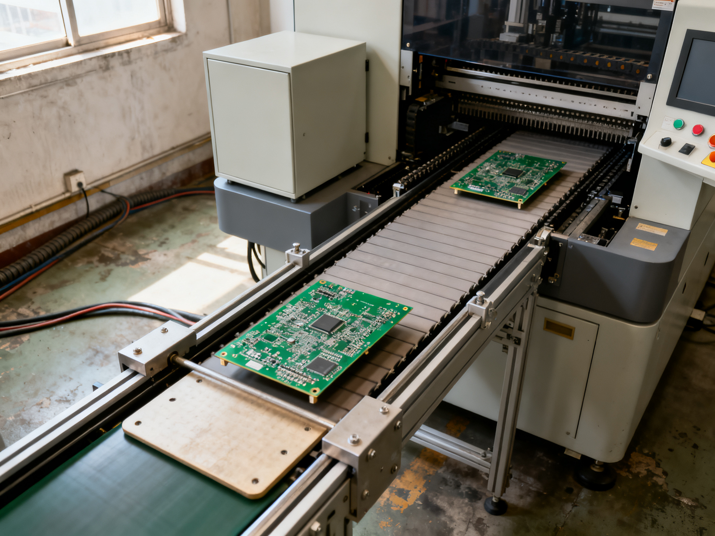
A U-shaped line packs more stations into the same floor area, and it separates a hot process from a cold one, which helps with cooling and with operator comfort. Turns also let you feed parallel inspection or rework paths from a single upstream machine, so a reject lane can run beside the good-board lane instead of crossing traffic.
The things that go wrong
- Alignment accuracy. A board that lands a few degrees off rotates into the lane guard or jams against the rail.
- Transfer time. Every turn adds a cycle-time penalty compared with straight travel, and on a tightly balanced line that penalty shows up as a printer waiting.
- Component clearance. Tall parts, heat sinks, and connectors need vertical and lateral room during rotation. Under-side clearance matters too, because the board often rides on a transfer plate during the move.
- Stability. Heavy or double-sided assemblies shift if the transfer surface is slick or if the drive stops mid-move.
- Maintenance. More moving parts means more things to wear. Sensors on corner units are a frequent cause of phantom jams, because a panel that has rotated into position can shadow a photo-eye that normally sees clear.
- Failure recovery. If the corner jams with a board half-turned, does the operator pull the board out by hand, or does the unit have a defined recovery sequence? Ask for that in writing before the machine ships.
Expert Tip: Run your widest panel through the corner with the tallest components you build, at line speed, ten times in a row. Corners pass bench tests and fail in production, and the difference is usually panel geometry, not the mechanism.
For lines that already run lead-free reflow and wave soldering with tight buffer requirements, suppliers that build the oven, the cooling section, and the inline handling together tend to have fewer handshake surprises. That is one practical reason to source the whole chain rather than mix brands, and it is why suppliers such as S&M Co. Ltd. (Shenzhen Chuxin Electronic Equipment Co., Ltd.) bundle conveyors with their reflow and wave soldering equipment for high-density, military, and semiconductor work.
In the next section, we’ll pull it together with a selection framework, so you can match the conveyor architecture to your product mix, takt time, and floor plan.## 6. Selection Framework: Match the Conveyor to the Process
Now the part where most buying decisions go sideways. A buyer shows up with a nice-looking spec sheet, compares belt speeds and prices, and picks the cheapest unit that fits the floor space. Three months later the line jams on a wide panel, and the conveyor gets blamed for a rail setting nobody documented.
Start with the process, not the catalogue.
Step 1: Map the line before you spec anything
Draw the flow with the real stations, in order, with the transfer points marked. Then write down what sits between each pair of machines. That inventory is usually a surprise, because operators have added a hand-off trolley, a rework table, or a temporary scanner that nobody has in the documentation.
Step 2: Measure the boards, including the ugly ones
For each product family, record the panel width, length, thickness, mass, component height, and the amount of board edge exposed for gripping. Add the negatives: the widest board, the heaviest, the one with the tallest part, the one with the least free edge.
Step 3: Define takt and buffer need
Set the target boards per hour, then work backwards to conveyor speed and buffer slots, as covered in the inline section earlier. Leave recovery margin. A buffer sized to exactly the calculated upset duration gives you zero room the next time a machine faults.
Step 4: Identify thermal, ESD, and contamination risks
Where does the conveyor run hot, wet, oily, or dusty? Which stations need controlled ESD handling? Which need airflow and filtration?
Step 5: Confirm every interface in writing
Transfer height, rail datum, handoff gap, signal type, connector, and handshake behavior with each neighbouring machine. Do this before the order, not during commissioning.
A quick decision path
Moving boards between stations, moderate temperature?
  -> Belt conveyor (SMT conveyor belt)
       -> Entering or leaving a hot zone?
            -> Yes: SMT cooling conveyor
       -> Need takt matching or buffering?
            -> Yes: inline SMT PCB conveyor with buffer slots
       -> Need a direction change?
            -> Yes: PCB turn conveyor (corner, U-turn, or shuttle)
Requirements sheet to hand to suppliers
| Parameter | Target | Tolerance | Test method | Vendor response |
| — | — | — | — | — |
| Panel width range | Your mix | Plus margin | Load test with widest panel | |
| Panel mass | Your heaviest | Plus margin | Load test | |
| Component height | Your tallest | Plus margin | Clearance check | |
| Transfer height | Match adjacent machines | Plus or minus agreed | Measurement at install | |
| Speed range | Takt derived | As needed | Timing run | |
| Buffer slots | Calculated | Plus margin | Upset simulation | |
| Operating temperature | Process range | Full profile | Oven dwell test | |
| ESD handling | Per site program | Per standard | Vendor declaration | |
| Fault behavior | Defined | Written | Power loss and block test | |
| Handoff signal | Matches neighbour | Exact | Bench handshake | |
| Traceability | If required | Optional | Barcode read test | |
Must-have versus nice-to-have
Keep this separation tight, or you will overbuy and then under-specify the parts that matter.
| Must-have | Nice-to-have |
| — | — |
| Correct width range and load rating | Automatic width control |
| Matching transfer height and rail datum | Automatic board counting |
| Defined fault and recovery behavior | Andon status towers |
| ESD handling for the site program | Barcode or 2D code traceability |
| Written handover behavior with neighbouring machines | Bypass routing |
| Spare belt or chain in the correct material grade | Recipe-driven cooling profiles |
Pro Insight: Spec the worst-case PCB, not the average one. The average board will pass on any conveyor, so it tells you nothing. The panel that jams, marks, or twists is the one that decides whether the unit was worth buying, and it is rarely the board on the factory’s marketing sheet.
Acceptance testing, before the invoice
Run the line with production boards, not samples. Test normal flow, a blocked downstream station, a missing board, an oversized board, a width change, a power loss and restart, the alarm states, the guards, and manual bypass. Sign off on observed behavior, not on a checklist the vendor fills in on paper.
If your line combines reflow, wave soldering, cooling, and inline handling, it is worth asking whether one supplier should own the whole chain. That is the argument S&M Co. Ltd. (Shenzhen Chuxin Electronic Equipment Co., Ltd.) makes with its lead-free reflow ovens, wave soldering systems, and matching conveyor sections, and it removes a whole category of handshake problems before they start.
The final section pulls this into a short buying checklist you can take into a supplier meeting.## 7. Integration, Controls, and Line Compatibility
A conveyor that runs fine on the bench can still wreck a production line. And the failure rarely comes from the belt. It comes from the interfaces: transfer height off by 2 mm, a rail datum that does not match the printer’s, a handshake signal arriving late. So this section is mostly about interfaces, since that is where the hours get lost.
Mechanical checks first
| Check | What “good” looks like |
| — | — |
| Transfer height | Board surface is level across every station handoff, with the tolerance agreed in writing |
| Rail datum | Conveyor rails match the adjacent machine’s rails in height and lateral position |
| Board handoff gap | Gap between conveyor and machine is tight enough to support the board, wide enough to avoid contact |
| Underside clearance | Room for standoffs, heatsinks, and the transfer plate under the panel |
| Access | Room to pull the belt, change a sensor, or lift a panel out without dismantling half the line |
| Guarding | Interlocked covers at nip points and hot zones, with a manual reset |
| Floor space | Footprint plus service aisle, checked against the actual layout, not the CAD drawing |
Electrical, controls, and software
Then the part people gloss over. Ask each supplier to answer in writing: what power the unit needs and whether it can ride on the line’s existing supply; what the emergency stop actually does to the belt, the buffers, and the upstream machine; which interlocks are hardwired and which are software; what the handshake with each neighbour looks like, including signal type, connector, and timeout behavior; how recipes and rail widths are stored and recalled; and whether board data can be passed to an MES with a real board ID attached.
Ask for the protocol version by name, too. “Industry standard compatible” tells you nothing. A supplier who can state the convention and the revision they support is a supplier who has already debugged it on someone else’s floor.
Upstream machine --(ready / board sense / fault)--> Conveyor controller
Conveyor controller --(zone ready, WIP count)--> Downstream machine
Controller <--(recipe, width, board ID)--> MES / traceability system
Emergency stop --> hardwired interlocks on every motor and actuator
Pro Insight: Get the fault behavior on paper before the order. If the downstream machine stops, does the conveyor hold the board, back up, or keep feeding? That single answer is the difference between a 90-second reflow fault and a 20-minute recovery, and it is almost never in the sales brochure.
Commissioning sequence
| Test | Watch for |
| — | — |
| Normal production run | Boards hand off without manual nudging |
| Downstream machine blocked | Buffer fills, upstream receives the stop, no boards drop |
| Missing board | Sensor flags it, no phantom jam |
| Width change | Rails and stop position adjust without a crash |
| Power loss and restart | Machine returns to a defined state, no double-feeding |
| Alarm states | Fault text matches reality, reset is straightforward |
| Manual bypass | Operator can route a board around a failed unit |
| Traceability read | Board ID captured and passed to MES correctly |
Run these with production boards, not showroom samples. If your line mixes reflow, wave soldering, cooling, and inline handling, ask whether one supplier should own the whole chain; that removes a category of handshake problems before they start. The next section pulls everything into a short buying checklist you can carry into a supplier meeting.## 8. Reliability, Maintenance, and Total Cost of Ownership
The conveyor quote is the smallest part of what a conveyor costs you. I have watched buyers sign off on a cheap unit and then spend two years replacing belts, paying freight for spares, and losing shift time to jams that a better-documented machine would have flagged in week one.
Price is a line item. Lifecycle cost is the story.
A 3 to 5 year cost view
| Cost line | What drives it | Typical behaviour over 5 years |
| — | — | — |
| Purchase price | Width range, buffering, cooling type | One-time, but the smallest line on a high-volume line |
| Energy | Motor load, fans, heaters, idle running | Scales with shifts and idle hours, not with product volume |
| Belts and wear parts | Material grade, temperature exposure, board edges | Replace on condition, and the material grade changes the interval |
| Cleaning | Flux residue, solder dust, packaging debris | Weekly effort, and it grows if the filters are skipped |
| Spare parts | Availability and lead time | Low cost, high pain when the line is down waiting |
| Downtime | Failure modes and recovery behaviour | Usually the largest and least visible cost |
| Service life | Frame, drives, rails, controller | Motors and drives often outlast the first belt by years |
The line that surprises people is downtime. A 40-minute stop on a line running three shifts is not 40 minutes, it is roughly a shift’s output for that station plus the recovery queue behind it.
Preventive maintenance calendar
Every shift    Clean belt surface and rails, check tracking, wipe sensors
Weekly         Inspect tension, rail parallelism, fan and filter condition
Monthly        Check motor and drive noise, review alarm history, verify sensors
Quarterly      Measure belt wear and edge condition, torque checks, lubrication per OEM
Annually        Full electrical and safety interlock check, controller backup
Intervals follow the OEM and the condition, not the calendar. That is worth saying plainly, because generic “replace every six months” advice is how plants end up changing good belts early and bad ones late.
Downtime risk matrix
| Failure mode | Likelihood | Impact | Best defense |
| — | — | — | — |
| Dirty or misaligned sensor | High | Medium | Weekly clean, spare sensor on the shelf |
| Belt wear or tracking drift | High | High | Condition-based checks, matched spare belt |
| Cooling fan or filter fault | Medium | Medium to high | Filter change in the schedule, spare fan unit |
| Motor or drive failure | Low | High | Critical spare, documented recovery sequence |
| Rail or frame damage from a jam | Low | High | Guarding, clear jam procedure, trained operators |
Alarm history is the cheapest diagnostic tool you have. A conveyor that throws the same code every third shift is telling you exactly which sensor to look at, and most plants throw that data away.
Documentation and remote support matter for the same reason. If a vendor can send drawings, controller software, and a trained response within a set time, a 2-hour fault becomes a shift. If the nearest engineer is a nine-hour flight away, the same fault becomes a week. Modular design, local service coverage, and stocked spares all pull the same lever: time to recover.
If your line mixes reflow, wave soldering, cooling, and inline handling, ask whether one supplier should own the chain, the way S&M Co. Ltd. (Shenzhen Chuxin Electronic Equipment Co., Ltd.) pairs its lead-free reflow ovens and wave soldering systems with matching conveyor sections. One throat to call, one set of drawings, one maintenance plan. Fewer handshake surprises during commissioning, and fewer fingers pointed in the wrong direction at 2am.## 9. Conveyor Type Comparison Table
Here is everything from the guide on one page, so you can compare the five families before you pick one.
| Conveyor type | Main purpose | Best position in the line | Key specs to confirm | Advantages | Limitations | Relative cost / complexity |
| — | — | — | — | — | — | — |
| Standard belt conveyor (smt conveyor belt) | Move panels between stations | Printer to placement to inspection | Width range, load, speed, transfer height, rail datum | Cheap, simple, easy to maintain | No cooling, no buffering, poor with hot or greasy zones | Low / low |
| SMT cooling conveyor | Bring board and component temperature down | Directly after reflow or wave solder | Airflow or zone capacity, exit board temperature, filtration | Protects solder joints, operators, and AOI accuracy | Costs floor length and energy, needs filters | Medium / medium |
| Inline SMT PCB conveyor (linking) | Carry and accumulate boards | Between any two machines | Buffer slots, board pitch, speed, handshake | Absorbs cycle-time gaps, easy to integrate | Adds length, more sensors to fail | Medium / medium |
| Inspection / buffer conveyor | Stop or index each board for review | Before AOI, SPI, or rework | Stop accuracy, throughput per hour, traceability | High control, clean board separation, data capture | Slower than continuous motion | Medium to high / high |
| PCB turn conveyor | Change board direction | Corners, U-turns, parallel lanes | Rotation accuracy, cycle penalty, clearance, footprint | Saves floor space, feeds parallel paths | Adds transfer time and failure points | High / high |
Quick selector: problem to solution
| Your problem | Start with |
| — | — |
| Boards arrive too hot to handle | SMT cooling conveyor |
| Printer waits while reflow catches up | Inline buffer conveyor |
| Not enough floor space for a straight line | PCB turn conveyor |
| Every board must be inspected | Inspection conveyor |
| Legacy line, limited budget | Standard belt conveyor |
Best fit by sector: consumer electronics and mixed-product lines lean on standard belt plus inline buffering. Semiconductor and aerospace work usually needs inspection and traceability. Automotive, military, and high-density builds add cooling and defined fault behavior.
Suppliers such as S&M Co. Ltd. (Shenzhen Chuxin Electronic Equipment Co., Ltd.) build these sections alongside lead-free reflow ovens and wave soldering systems, which keeps transfer heights and handshakes consistent across the chain.## Conclusion: Specify the Line, Not Just the Conveyor
The best conveyor is not the one with the longest spec sheet. It is the one that fits your boards, your heat, your takt time, your floor plan, and your neighbours’ signals. Get those five right and the unit is almost boring. Get one wrong and it becomes the reason your printer waits all shift.
Four steps before you issue an RFQ
- Document the worst-case PCB. Width, mass, component height, edge clearance, layer count, and the board that has caused trouble before.
- Map today’s bottlenecks. Where does WIP actually stack up, and which machine starves first?
- Write the specification, then the acceptance test. Both in one document, so nothing gets negotiated away later.
- Validate with representative boards. Production panels, at line speed, at temperature, before the invoice clears.
From Our Experience: This box will carry a verified case once a named author and technical reviewer are assigned. Placeholder for a documented project lesson or a credentialed expert interview on worst-case board testing and integration problems. No figures are stated here until they can be sourced.
Suppliers that build the oven, the cooling section, and the inline handling together tend to remove handshake problems before commissioning, which is the argument S&M Co. Ltd. (Shenzhen Chuxin Electronic Equipment Co., Ltd.) makes with its lead-free reflow ovens, wave soldering systems, and matching conveyor sections for high-density, semiconductor, and military lines.
Ready to spec your line? Request a line-layout review and a conveyor specification consultation from the supplier, and bring your worst-case board with you.## Priority Research Focus (Planning Appendix)
Internal working note. This appendix is not part of the published article. It records what still needs to be sourced, who needs to sign off, and where the current draft is knowingly incomplete.
Status: research blocked, article shipped with placeholders
All 10 research queries returned no usable results. The search tool hit a quota error on every call, so zero sources were retrieved and zero citations were added to the body of this guide. That matters for how you read the article today.
What this means practically: every number that would normally carry a citation is either a worked example you can re-run with your own data, or it is a vendor-style description of how a machine behaves. We would rather publish that than publish a statistic we cannot trace back to a document. The cooling example in section 3 is labelled as an assumption set on purpose, and the editorial note under the introduction says the same thing.
Priority 1: Standards and compliance, to be verified before republication
Nothing in the current draft asserts a standard requirement. The interface and compliance topics below are named as open research items, not as claims:
- Machine-to-machine communication for SMT conveyors: IPC-HERMES-9852 (Hermes Standard), the legacy SMEMA electrical handshake convention, and IPC-CFX / IPC-2591 for connected factory data exchange
- ESD handling: IEC 61340-5-1 and ANSI/ESD S20.20
- Machinery safety: ISO 12100 (risk assessment), IEC 60204-1 (electrical equipment of machines), plus guarding and emergency stop function
- Regional obligations: EU CE marking and the Regulation (EU) 2023/1230 transition, UK and US treatment
- Environment and process: RoHS, REACH, IPC J-STD-001 for soldering workmanship
- Sector expectations: automotive (IATF 16949 customer flowdowns), aerospace and defence, semiconductor
We need to separate, in writing, what is law, what is a voluntary customer standard, and what is a buyer preference. We also need edition numbers and effective dates, since a 2026 guide that cites an older edition without saying so is worse than no citation at all.
Priority 2: Engineering data, to be collected with attributable sources
| Data needed | Preferred source type | Current state |
| — | — | — |
| Board width, length, mass, component height limits | OEM technical datasheets | Vendored in draft, not cited |
| Conveyor speed ranges and indexing accuracy | OEM manuals | Described qualitatively only |
| Cooling capacity and exit temperature behaviour | OEM data plus peer-reviewed thermal work | Worked example only, assumptions labelled |
| Buffer sizing and takt equations | Industrial engineering research | Method shown, no cited source |
| Failure modes and downtime impact | Maintenance and reliability literature plus plant case studies | Risk matrix is judgement, not data |
| Total cost of ownership inputs | OEM maintenance guidance | Framework only, no figures |
Rule for this pass: if the only source is a vendor brochure, say so in the sentence, or drop the claim. Where two vendors publish different numbers for the same parameter, the honest entry is “vendor dependent.”
Priority 3: People, credentials, and first-hand evidence
Three gaps need closing before this guide can carry reviewer attribution:
- A named author with verifiable SMT, PCB handling, soldering, or electronics manufacturing experience, and at least one measurable project contribution
- A technical reviewer with stated credentials, replacing the reviewer placeholder in the metadata block
- One documented, first-hand implementation example, plus two attributable expert insights, one on board-edge, transfer height, and handshake checks, one on measuring actual board temperature after reflow
Vendor experience does not count as the author’s experience. The “From Our Experience” box stays as an empty callout until a real case with real numbers exists.
Source log ranking rule for the next pass
- Standards bodies and government sources
- Peer-reviewed research
- Established OEM technical documentation
- Clearly identified practitioner interviews and factory case studies
Each source gets a full audit line: working URL, title, issuing body or author credentials, publication or update date, source type, whether it is primary or first-hand, the one conclusion it supports, and an E-E-A-T rating with a reason.
What still needs writing once sources land
- A source-backed section on interface standards, replacing the current descriptive treatment of handshakes
- A citation for the cooling-load method, or a vendor comparison table with named cooling capacities
- A buffer-sizing equation with its source and assumptions stated on the page
- A maintenance and TCO section with intervals attributed to OEM guidance rather than the calendar
- A short FAQ built from long-tail buyer questions found in OEM RFQ guidance
Until then, the published guide stands on mechanism, method, and clearly labelled assumptions, which is a defensible place to be.
Keyword and Supporting Elements Map
Internal working note. This appendix is not part of the published article. It maps every seed and target keyword to the section where it earns its place, lists the visual and conversion assets the guide needs, and records which supporting assets are still missing.
Keyword placement plan
| Keyword | Placement in the published guide | Why there |
| — | — | — |
| SMT conveyor belt | Title, introduction, Section 2 (Belt Conveyors and SMT Conveyor Belts), Section 9 comparison table label, conclusion | Core phrase tied to the highest-intent section, plus the anchor in the title |
| belt conveyor | Section 2 explanatory passages, Section 9 quick selector | Broad head term for readers who do not know they need an SMT-specific unit |
| how PCB conveyor belt works | Section 2, first explanatory paragraph after the section header | Matches a question-style search, answered in plain language |
| SMT cooling conveyor | Section 3 heading and body, Section 9 table, quick selector | Dedicated intent, own H2, own table |
| SMT PCB conveyor | Section 4 heading and body, Section 9 table | Dedicated intent, own H2 |
| inline PCB conveyor | Section 4 body, Section 6 selection framework | Supports the linking and buffering intent |
| PCB turn conveyor | Section 5 heading and body, Section 9 table, quick selector | Dedicated intent, own H2 |
| PCB conveyor systems | Section 6 and Section 7 integration passages | Broader phrase for readers comparing whole systems rather than one unit |
| PCB handling equipment | Section 2 and Section 8 passages | Natural in reliability and maintenance context |
| SMT line conveyor selection | Section 6 heading and conclusion | Close variant of the guide’s primary intent |
Rule for this pass: no exact-match phrase in more than two consecutive headers. Descriptive technical wording carries the headers, and the keywords ride inside sentences where they read like speech.
Visual and asset inventory
| Asset | Section | Status |
| — | — | — |
| Annotated process diagram (printer to AOI flow) | Introduction | Done, plain code block |
| Layout diagram, L-shaped and U-shaped line | Section 5 | Done, plain code block |
| Belt material comparison table | Section 2 | Done |
| Belt options overview table | Section 2 | Done |
| Cooling configuration table | Section 3 | Done |
| Inline equipment function table | Section 4 | Done |
| Turn mechanism table | Section 5 | Done |
| Five-family comparison table | Section 9 | Done |
| Quick selector, problem to solution | Section 9 | Done |
| Requirements sheet for suppliers | Section 6 | Done |
| Decision path flowchart | Section 6 | Done, plain code block |
| Cost of ownership view over five years | Section 8 | Done |
| Downtime risk matrix | Section 8 | Done |
| Preventive maintenance calendar | Section 8 | Done, plain code block |
| Commissioning test matrix | Section 7 | Done |
| Signal and data flow diagram | Section 7 | Done, plain code block |
| Cooling load worked example | Section 3 | Done, assumptions labelled in the text |
| Maintenance checklist, printable one page | Section 8 | Missing, needs a standalone checklist asset |
| RFQ checklist for a supplier meeting | Conclusion | Missing, needs a boxed version of the Section 6 requirements sheet |
| Long tail FAQ block | End of guide | Missing, depends on buyer question research |
| Demonstration video, belt or turn conveyor in motion | Section 2 or Section 5 | Missing, needs permission and a working link |
Internal linking opportunities
Related guides on the site should link into this one with descriptive anchor text, and this guide should link out to them where they add context.
- Reflow oven profile and temperature control, linked from Section 3 on cooling
- Wave soldering conveyor conventions, linked from Section 3 and Section 5
- SMT line design and layout planning, linked from Section 5 and Section 6
- ESD control in electronics manufacturing, linked from Section 2 and Section 7
- Defect reduction and process control, linked from Section 3 and Section 8
What still needs sourcing before the next pass
The keyword map does not fix the research gap. Two things stay open. First, the long tail FAQ and the demonstration video need real buyer questions and permission-safe media, and neither exists yet. Second, the standards treatment in Section 7 remains descriptive. When interface standards get verified, the FAQ should point to them rather than restate them.
Last check on this map: every target keyword appears at least once in natural phrasing, and no section depends on an exact-match phrase to make sense. That is the bar. Hold to it when the next draft comes back.