
Published: 17 November 2026
Reading Time: 12 minutes
Reviewer: [PLACEHOLDER, reviewer name to be supplied by S&M Co. Ltd. engineering team]
Reviewer Credentials: [PLACEHOLDER, e.g., Senior SMT Process Engineer, S&M Co. Ltd. / IPC-A-610 Certified Specialist]
Why PCB Preheating Decides Whether a Selective Soldering Run Passes or Fails
Here is the scene. A board comes off the selective solder line looking fine under the AOI. Then it lands on the test bench and half the through-hole joints read as opens. The paste looks smooth. The nozzle temperature was on target. The flux was fine. Everybody stares at the process sheet. Nobody looks at the preheat.
That happens more often than people admit, because preheating is the quiet step. It happens before anyone is watching for defects, in a zone that is half a meter from the interesting part of the machine. And yet every joint the nozzle touches is already decided by the temperature the board carried into that moment.
So, how is PCB preheating for selective soldering actually done? Not the sales-deck version. The real sequence, with the numbers, the hardware choices, and the ways it fails.
The short version
Selective soldering only works when the board reaches a uniform, controlled temperature before the solder makes contact. Preheat is what buys you that window. Get it right and the solder wets quickly, the flux has time to do its job, and the joint forms the way the design intended. Get it wrong and you are gambling.
The four failure families that show up on a preheat-staged line are consistent enough to name:
| Symptom | Usually traced back to |
|—|—|
| Cold joints, poor wetting, incomplete hole fill | Board too cool at solder contact, no thermal soak |
| Solder balling and spatter on QFN perimeters | Flux not activated and dried before hot contact |
| Non-wetting, dull grainy fillets | Cold solder, slow or stalled ramp, poor board uniformity |
| Discoloration, warpage, lifted pads, cracked joints | Excessive soak, too hot a profile, thermal shock on exit |
Notice the pattern. Too little heat and you get bad joints. Too much heat and you get damaged boards. The window is real but it is not tiny, and it is not guesswork.
What this article walks through
The sections below break the process into the parts you can actually control:
- Where preheat sits in the selective soldering cycle, and why the sequence matters
- The physics behind cold joints, poor wetting, and why board-to-solder temperature difference drives everything
- Convection versus infrared versus hybrid versus hot-air knife preheating, and where each one wins
- A practical temperature guide for lead-free and leaded processes, including ramp rate and soak logic
- Thermocouple placement and profile verification, so the numbers on the screen match the board in the machine
- Defect-to-cause mapping for the nine most common preheat-linked problems
- High-density and lead-free optimization for BGA, QFN, and multilayer boards
Throughout, we draw on what we see running lines in the field, where a lot of “flux problem” tickets turn out to be preheat problems wearing a disguise.
Expert Tip: When a customer sends back a board with solder balling and insufficient wetting on the QFN perimeters, the first thing we check is not the paste and not the nozzle. We check where the board-top thermocouple was mounted and whether the preheat zone was tuned for a 10-layer board and then inherited by a 4-layer job. That mismatch accounts for a surprising share of the “we changed the paste and nothing happened” cases.
If you want the short version of the promise: by the end of this article you should be able to write a selective solder preheat recipe, verify it with a probe, and defend it with data.
About the author
Written by [PLACEHOLDER, author name to be supplied], [PLACEHOLDER, job title] at S&M Co. Ltd. (Shenzhen Chuxin Electronic Equipment Co., Ltd.), where the author has [X] years of experience designing and supporting surface mount technology equipment, including lead-free reflow ovens, wave soldering systems, and fully integrated SMT production lines for consumer electronics, semiconductor, and military-grade assembly. The work centers on soldering profile development, BGA and QFN defect analysis, and RoHS-compliant line upgrades across Asia and North America.
Ready to compare profiles on your own line? Send us a board and your current recipe, and we will run it through one of our wave soldering or integrated SMT setups so you can see the difference side by side.
Published: 17 November 2026
Reading Time: 12 minutes
Reviewer: [PLACEHOLDER, reviewer name to be supplied by S&M Co. Ltd. engineering team]
Reviewer Credentials: [PLACEHOLDER, e.g., Senior SMT Process Engineer, S&M Co. Ltd. / IPC-A-610 Certified Specialist]
About the Author
[Author headshot placeholder: insert a square photo, 400px wide, of the author in SMT production attire]
Written by [PLACEHOLDER, author name to be supplied], [PLACEHOLDER, job title], S&M Co. Ltd. (Shenzhen Chuxin Electronic Equipment Co., Ltd.). [X] years of experience designing and supporting surface mount technology equipment, including lead-free reflow ovens, wave soldering systems, and fully integrated SMT production lines for consumer electronics, semiconductor, and military-grade assembly. The work centers on soldering profile development, BGA and QFN defect analysis, and RoHS-compliant line upgrades across Asia and North America.
Company logo placeholder: S&M Co. Ltd. / Shenzhen Chuxin Electronic Equipment Co., Ltd.
Credentials
- [PLACEHOLDER, certification or training, e.g., IPC-A-610 Certified Specialist]
- [PLACEHOLDER, certification or training, e.g., IPC J-STD-001 Certified Specialist]
- [PLACEHOLDER, education or professional background]
A note on how this article was built. Every temperature range, ramp limit, and defect map here comes from published standards work, equipment documentation, and running production lines. No figure in this piece is vendor marketing copy. Where an industry-wide number does not exist, we say so instead of inventing one.
Ready to compare profiles on your own line? Send us a board and your current recipe, and we will run it through one of our wave soldering or integrated SMT setups so you can see the difference side by side.## Why Preheating Matters: The Physics Behind Poor Wetting and Thermal Damage
Strip away the machine, strip away the nozzle, and selective soldering comes down to one question: how much heat has the board already absorbed by the time molten solder touches it? Everything else is downstream of that.
Preheat does two jobs, and lines usually fail at one of them before the other.
Job one is closing the temperature gap. Molten SAC305 leaves a nozzle at roughly 260 to 300 °C. The liquidus of the alloy itself sits near 217 °C. If your board is sitting at 25 °C, the solder has to dump a huge amount of energy into the pad, the barrel wall, and the surrounding laminate just to reach wetting temperature. That energy comes out of the joint, and it comes out fast. You get a short-lived molten pool that wets the barrel and the lead, then freezes before it fills the hole properly. That is a cold joint, and it looks exactly like a cold joint under AOI.
Preheat closes the gap so the solder arrives at a joint that is already close to molten temperature. Now the solder only has to do wetting work, not all the heating work. The joint forms fast, the fillet curves where it should, and the barrel fills.
Job two is flux activation and drying. Liquid flux is roughly 90 percent solvent by weight for most no-clean formulations. Under a hot nozzle, that solvent boils. Vapour bubbles push molten solder outward, and you get solder balls and spatter around the joint. This is the classic “flux problem” that turns out to be a preheat problem.
The solvent needs to evaporate before hot contact, and the flux needs enough thermal energy to reach its activation point. That takes time and a deliberate ramp, which is exactly what a preheat zone provides.
| Board temperature at solder contact | What the solder experiences | Result |
|—|—|—|
| Near room temperature | Large ΔT, energy dumped into pad and barrel | Slow wetting, cold joints, incomplete hole fill |
| 100 to 130 °C | Moderate ΔT, molten pool holds briefly | Acceptable on leaded, marginal on dense lead-free |
| 150 to 175 °C | Small ΔT, wetting driven by chemistry not heat | Good wetting, clean fillets, low balling |
| Above 200 °C | Little ΔT, but flux already spent | Package stress, oxidation, possible dry-out residue |
Now the other side of the coin. Too much heat is not safe.
Solder alloys form intermetallic compounds at the pad interface, layers of brittle copper-tin or copper-silver phases. That is normal and unavoidable. The rate of growth, though, depends on temperature and time above the alloy’s melt point. Push a board hard into a hot soak and you accelerate the growth of intermetallics, which is a classic contributor to brittle, cracked joints and reduced fatigue life. Copper dissolution into the solder follows the same logic. More time hot means more copper consumed, which means thinner pad interfaces.
Package damage shows up too. Soldering heats one side of the board while the other side stays cooler. That gradient drives warpage. Ceramic and plastic packages have their own limits on how fast you can ramp them, and multilayer laminates have their own, usually around 3 °C per second as a common ceiling rather than a target.
And there is the exit. A board that leaves the preheat zone at 170 °C and meets a nozzle at 280 °C gets a thermal shock. A board that leaves at 200 °C and is then cooled aggressively gets a worse one. Discoloration, lifted pads, delamination, and cracked joints all trace back here often enough that we check exit temperatures before we check anything else.
From what I have seen on customer lines, the most common mistake is not picking the wrong temperature. It is picking a temperature that suits the average board and applying it to every board. A mixed-technology board with a BGA, a QFN, and a plastic connector does not have one thermal mass. It has three. The connector’s plastic body can be sitting 30 °C cooler than the BGA’s solder mask when the setpoint reads 160 °C.
That is why we teach this the way we do. Measure the component body, not the board surface. Not the air, not the setpoint, not the conveyor plate. The part that is actually going to form the joint.
From Our Experience: A board family that mixed 0402 passives with a 48-pin QFN on six-layer FR-4 kept coming back with a mix of cold joints on the QFN and clean joints on the passives. The setpoint looked fine on the HMI. When we put a thermocouple on the QFN body instead of the board surface, we found the component was running 40 °C cooler than the recipe assumed. Nobody had checked. The preheat zone had been tuned on a different product line years earlier and never revisited.
Here is the mental model to carry into the rest of this guide. Preheat is a controlled energy input, not a setpoint to copy off someone else’s process sheet. The right answer depends on board construction, layer count, copper coverage, package mix, alloy, and flux chemistry. We will get into the numbers, the methods, and the ways to verify them next.
If your line is running fine in the morning and drifting by lunch, the usual suspects are the oven, not the board. We can put a profile on your boards and show you the difference in writing, with numbers, rather than adjectives. Send us a sample and your current recipe, and we will run it through a wave soldering or integrated SMT setup so you can compare the two side by side.## The Preheating Step in Context: Where It Sits in the Selective Soldering Cycle
Here is the thing most process sheets get wrong on day one. They treat preheat as a temperature number that lives in its own little box, separate from everything else. So somebody sets 150 °C, never checks the board, and calls it done. Meanwhile, the board is running through a sequence that has four separate heat inputs, and only one of them is the one they control.
Here is how PCB preheating for selective soldering is done, in order, on a real line.
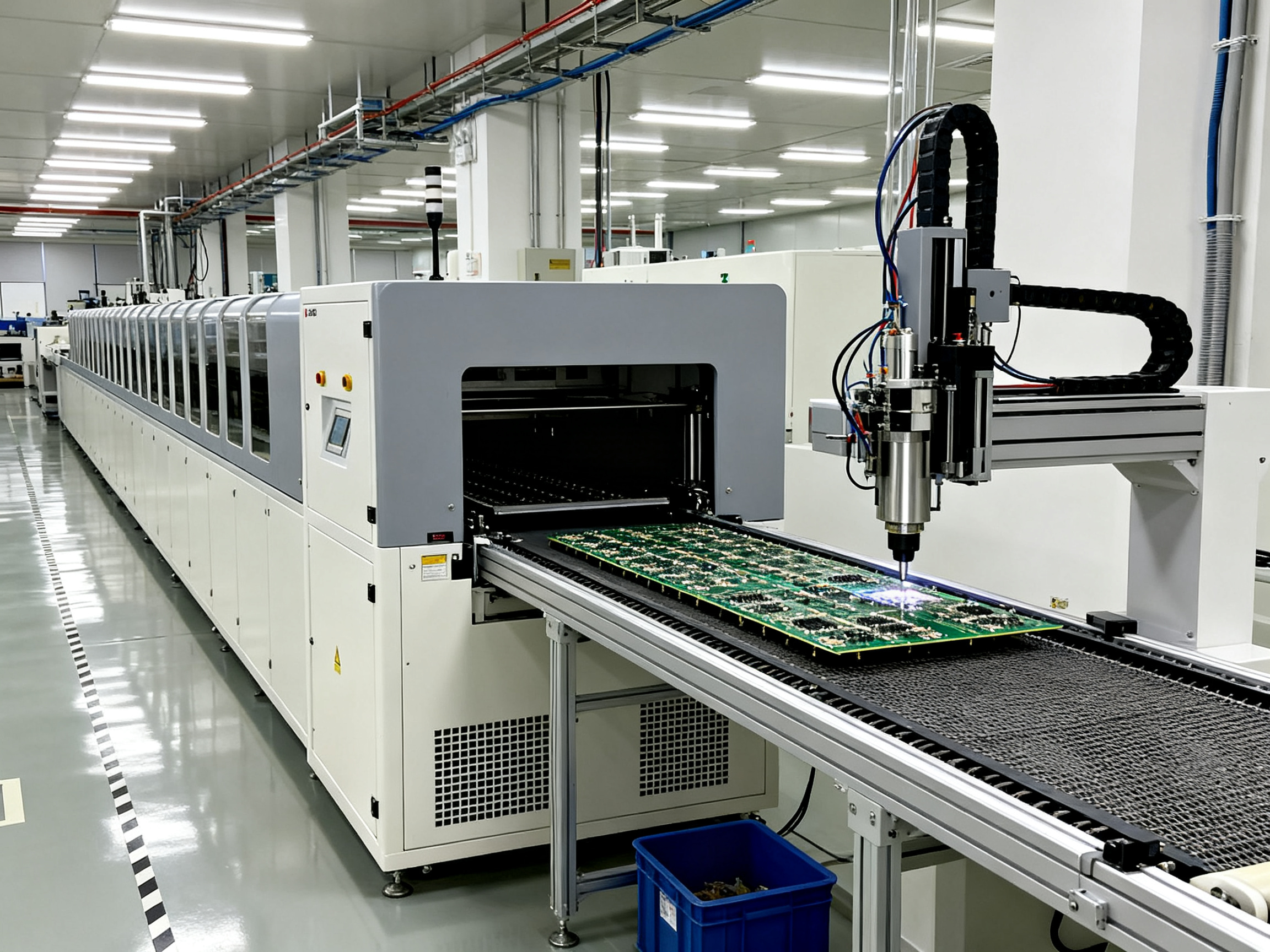
The sequence, start to finish
| Step | What happens | Why it matters for heat |
|—|—|—|
| 1. Flux dispensing or printing | No-clean or no-clean-compatible flux is applied to through-hole pads and joints | Flux is applied cold, then it sits in the zone before solder contact |
| 2. PCB loading | The board enters on the conveyor or fixture, usually on a heated pallet or carrier | The board starts at whatever temperature the shop floor and the carrier have given it |
| 3. Preheat zone | Controlled ramp and soak, usually one or more tunnel sections | This is the only chance you get to set board temperature before solder contact |
| 4. Solder contact | Nozzle/dip selective soldering, or a wave pot | Molten alloy arrives at roughly 260 to 300 °C for lead-free |
| 5. Cooling | Controlled, often a dedicated cooling tunnel or fan array | Too much cooling shock on exit causes warpage and cracked joints |
| 6. Inspection | AOI for solder, fillets, and balls; X-ray for hidden joints | Confirms what the preheat set was supposed to guarantee |
| 7. Cleaning | Flux residue removal, often aqueous or solvent based | Happens after thermal exposure, so it cannot fix preheat problems |
Notice where preheat lands. It is step three, after flux and before solder. That position is not arbitrary. It is the only slot in the sequence where you can raise the board to a known temperature while the flux is still fresh, still wet, and still has time to dry.
Expert Tip: Why I ramp preheat slowly and hold a conservative soak instead of chasing the theoretical solder liquidus: as an SMT equipment engineer, I always treat a 15 to 20% undershoot in preheat temperature as safer than an overshoot. On BGA and QFN boards, the dominant failure mode is thermal damage to components and interconnects, not cold joints. A slightly cool board produces a marginal joint you can rework. A cooked board produces a lifted pad you cannot.
Preheat is a ramp, not a soak at peak temperature
This distinction trips up a lot of people. Preheat is a controlled ramp followed by a controlled soak. It is not “hold the board at 200 °C for 30 seconds,” and it is not the soldering temperature.
The soldering temperature is the temperature of the molten alloy at the nozzle or in the pot. That is a different thing entirely. The board temperature at solder contact is the preheat outcome. When a service engineer says “the machine was at 280 °C,” they are describing the pot, not the joint. Those two numbers should never be quoted as if they describe the same thing.
Then there is cooling, which people also blur into preheat. Exit cooling is where thermal shock lives. A board that leaves the preheat zone at 170 °C and meets 280 °C solder, then gets blast-cooled, has been through two shocks in one moment. That shows up later as discoloration, delamination, and cracked joints.
Selective soldering versus wave soldering
Both use preheat. The mechanics differ.
In selective soldering, the nozzle touches one joint at a time. Heat is applied locally and briefly, so the board itself does very little of the heating work. Preheat carries most of the load, and the exposure window per joint is short.
In wave soldering, the entire bottom of the board passes through a wave of molten solder at once. There is a lot of bulk metal in contact with the board, and it stays in contact longer. That usually means wave lines run a longer preheat soak and a slightly higher top-side target, because the wave itself acts as a second heat input after the preheat zone has done its job.
Here is where we push back on the common version of that claim. Bath thermal mass is part of the story, but not all of it. The bigger driver is the dwell time in the wave and the thermal mass of the board. A wave line running at 2.5 m/min with a 4-meter wave section holds the board in contact far longer than a selective nozzle touching a single joint for 2 seconds. We have seen lines fix “wave needs more preheat” by slowing the conveyor instead of raising the setpoint, and the joints got better with less thermal load on the board.
And one more thing. The flux interval is where lines get into trouble. Flux sits on the board from deposition until solder contact. Too long, and the solvent can flash off before the board is hot enough to activate the flux properly. Too short, and the flux has not dried. There is no universal maximum interval, so your own data is the reference. Log the time from flux deposition to solder contact on every recipe, and watch it drift when line speed changes.
If you want to see the sequence with real numbers on your own boards, send us a sample and your current recipe. We will run it through a wave soldering or integrated SMT setup, and you can compare the profiles side by side, in writing, with temperatures you can check.
[Section image placeholder: process flow diagram of a selective soldering line showing flux dispense, preheat tunnel with zone temperatures, nozzle contact, cooling tunnel, AOI, and clean, plus a photo of a conveyor preheat tunnel with labeled zones]## Preheat Methods Compared: Convection, Infrared, Hybrid, and Hot-Air Knife
So you have decided the board needs to be hotter before the nozzle arrives. Now you have to pick the method, and this is where lines get into trouble, because vendors will happily sell you a hot-air knife when what the job actually needs is top-side heating.
Four methods dominate real production floors in 2026: forced hot air, infrared, hybrid infrared plus convection, and localized hot-air knives.
Hot-air convection
Forced air across the board, either in a tunnel with recirculation or as a focused nozzle array. This is the classic preheater on most selective and wave lines, and for good reason. Convection heats the board surface evenly, and recirculating hot air reaches around component bodies better than radiation does.
Where it struggles is speed and energy. Convection is a slow heat transfer mechanism. Air has poor thermal conductivity compared with radiation, so getting a heavy multilayer board up to temperature takes a longer ramp and more dwell than an IR lamp would need. On a tunnel, that means more zones, longer machines, and more heater energy per board.
Also worth knowing: convective heating is airflow dependent. A blocked return duct or a dirty filter changes your profile. We have seen lines chase a drifting preheat profile for months before somebody opened the cabinet and found a filter packed solid with solder flux aerosol.
Infrared heating
IR lamps and medium-wave quartz emitters deliver radiation straight to the board. IR is fast. A lamp can put a serious amount of energy into a board surface in a short window, and the ramp rates we measure on IR-only preheaters are noticeably quicker than convection at the same target temperature.
The catch is shadowing. Radiation travels in a straight line, so a tall connector, a heatsink, or a shielding can block the board underneath it. The board under the shadow runs cooler while its neighbour in the open heats normally. That is exactly the kind of board-to-board and feature-to-feature temperature spread that makes a uniform recipe impossible.
IR also heats by surface, so it favours the top side. Components with bottom-exposed terminations, like a QFN, do not benefit much, because the heat has to conduct down through the package and the solder mask before it reaches the joint.
Hybrid infrared and convection
This is the answer we recommend more often than anything else for modern high-mix lines. IR handles the fast bulk ramp, and convection evens out the distribution and fills in the shadowed areas.
The logic is simple. Convection alone is slow, so you add IR for speed. IR alone is uneven, so you add convection for uniformity. The combination gets a fast ramp and a flat top-side temperature at the same time, which is what a mixed-technology board needs.
From Our Experience: A customer running a 10-layer radar board with tall coax connectors had fought cold joints on the shielded connector pins for about a year. We replaced the single-zone convection preheater with a hybrid setup, IR ahead and convection behind, and the delta between the connector pins and the open board dropped from roughly 25 °C to under 8 °C. No change to the solder, no change to the flux, no change to the nozzle temperature. The joints fixed themselves once the board was actually uniform.
Hot-air knife (localized forced air)
A hot-air knife is a small, focused fan or nozzle that heats a tight area, often a single component group, sometimes at the same time as the conveyor preheat zone.
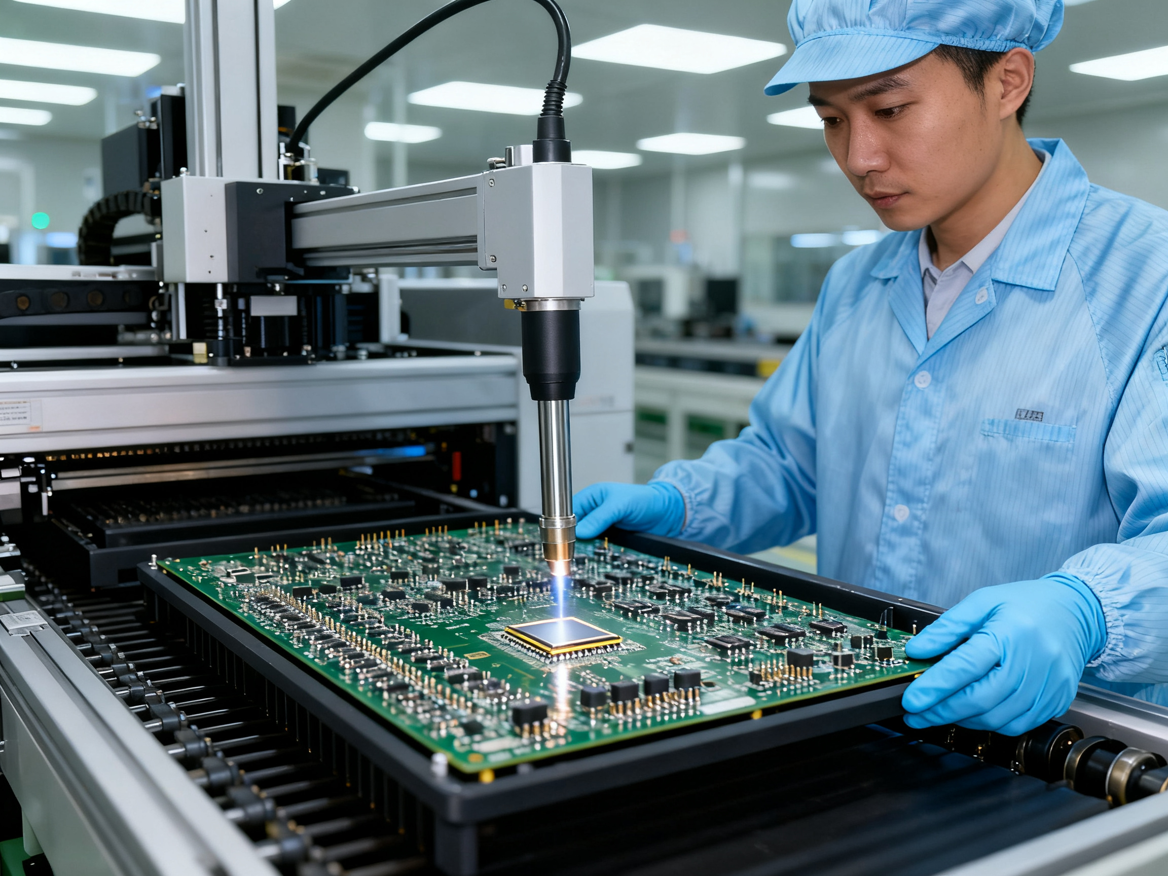
This is the tool for the cases where one-sided board heating simply is not enough. Bottom-terminated and bottom-exposed parts, QFN packages, bottom-contact LEDs, and connector shields that act as thermal sinks all fit here. If you have a component that is colder than the rest of the board no matter how you tune the tunnel, a knife lets you add energy exactly where it is needed without cooking the whole board.
The tradeoff is obvious. A knife is manual or semi-manual, it depends on operator skill and standoff distance, and it does not scale well across a mixed model run.
| Method | Heating mechanism | Typical ramp | Top-side uniformity | Handles bottom-exposed parts | Best use case |
|—|—|—|—|—|—|
| Hot-air convection | Forced recirculated air | Moderate, 1 to 3 °C/s | Good, if airflow is clean | Partly, via conduction only | General-purpose tunnels, wave and selective lines with a wide mix |
| Infrared | Radiation from lamps or quartz emitters | Fast, 3 °C/s and above | Fair, shadowing around tall parts | Poor, top-side biased | Thick or heavy boards needing a quick bulk ramp |
| Hybrid IR plus convection | Radiation for ramp, air for evenness | Fast ramp with flat soak | Very good | Good, with tuned balance | High-mix lines, multilayer boards, dense connectors |
| Hot-air knife | Focused forced air at one point | Very fast locally | Local only | Yes, this is the method | Bottom-terminated QFN, LEDs, connector shields, thermal sinks |
One thing we want to push back on. People treat method choice as the answer to thermal problems, and it is often just one variable among several. Board construction, copper coverage, layer count, the component mix, the alloy, and the flux chemistry all set the size of the window you have to work in. A hybrid preheater on a badly balanced flux window still produces balling.
Where preheat alone cannot solve the thermal problem, the honest answer is a different process: dual-side heating, a mini-wave or dip system, nitrogen atmosphere, or a board and carrier redesign that balances the copper. When you are down to one component on the board that will not behave, stop raising the preheat and start changing the geometry.
The method choice matters, but it sits inside a bigger system. In the next section we get into actual numbers: target temperatures, ramp limits, and soak logic for lead-free and leaded processes.
Ready to see how these methods perform on your own boards? Send us a sample and your current recipe, and we will run it through a wave soldering or integrated SMT setup so you can compare the two side by side, with temperatures and times in writing.
Setting Preheat Temperatures: A Practical Temperature Guide
Now for the part everybody actually wants: the numbers.
I am going to give you working ranges, not a recipe to copy blind. A range tells you where to start. Your board tells you where to land. We will walk through why.
The working numbers
For lead-free SAC305, a board preheat target of 130 to 160 °C is where most selective solder lines settle. For leaded Sn63Pb37, expect 110 to 140 °C. The molten solder at the nozzle or dip point typically runs 260 to 300 °C for lead-free work. Those are the three numbers that define the gap.
Here is a reference table to keep on the wall:
| Alloy | Board preheat target at solder contact | Solder pot or nozzle temperature | Notes |
|—|—|—|—|
| SAC305 (Sn96.5Ag3.0Cu0.5) | 130 to 160 °C | 260 to 300 °C | Higher flux activation demand, so push toward the upper end for dense boards |
| SAC305 on heavy copper or 8-layer-plus | 150 to 175 °C | 260 to 300 °C | Bulk heat capacity pulls the board down through the ramp |
| Sn63Pb37 (Sn63Pb37) | 110 to 140 °C | 235 to 260 °C | Lower flux activation temperature, lower thermal budget for plastic parts |
| Sn63Pb37 on plastic-heavy assemblies | 100 to 125 °C | 235 to 250 °C | Connector bodies and housings limit how high you can go |
| Bottom-terminated QFN or LED add-on | 160 to 185 °C targeted at the component | 260 to 300 °C | One-sided heating struggles here, add a knife or go dual-side |
| Mixed technology with a large connector | 140 to 165 °C, measured on the connector body | 260 to 300 °C | The connector body is the cold spot, not the board surface |
One important note before you use that table. The first row of real data I ask for from any line is the board temperature at solder contact, not the setpoint on the HMI. A preheat tunnel set to 160 °C can deliver anything from 110 to 165 °C at the board, depending on the board, the airflow, and the distance from the last heater to the nozzle. Setpoints are inputs. Board temperature is the outcome.
Ramp rate: the number people misuse
You will hear 3 °C per second quoted as a preheat ramp limit. Be careful with that. It comes out of component and laminate handling guidance, where it acts as a ceiling to protect moisture-sensitive devices and multilayer boards from thermal shock. It is not a target for selective soldering.
A practical selective solder preheat ramp sits somewhere between 1 and 2.5 °C per second for the bulk ramp, then drops into a soak. Slower than 1 °C per second and you are wasting line time and pushing the flux interval open. Faster than 3 °C per second and you risk stressing packages, delaminating, and driving moisture out of the laminate in ways that show up as blisters later.
The logic behind the ramp is about vapor pressure and stress. Ramp gently and any trapped moisture in the laminate has time to escape. Ramp hard and you create pressure inside the board. Also, gentle ramps give flux time to dry progressively rather than flash off all at once.
Pro Insight: Put the thermocouple on the coolest, heaviest thermal-mass component on the board, not on the board surface, and treat 10 to 15 seconds of dwell as a rule of thumb for the final soak. If your thermocouple reading lags the oven setpoint by more than roughly 10 °C at steady state, the problem is your heat transfer hardware, airflow, or zone balance, not your profile. Keep chasing setpoint changes and you will chase them forever.
Soak time is a function of thermal mass, not a number
This is where most process sheets go wrong. People write “soak 60 seconds” in the recipe box and never revisit it.
Soak exists so the heat reaches the inside of the board, not just the surface. A 1.6 mm two-layer board with light copper reaches temperature quickly. A 2.4 mm eight-layer board with heavy ground planes on both sides holds heat in the copper and takes much longer to equalize. Same oven, same setpoint, very different soak.
Practical drivers for soak length:
- Layer count and board thickness. More copper to heat means longer.
- Copper coverage. Large ground planes behave like a heatsink and absorb energy.
- Component mix. Plastic connectors and large BGAs change the local thermal load.
- Through-hole density. Dense pin fields mean more mass to bring up.
- Zone count and heater spacing. More zones let you soak without overshooting the setpoint.
On a multi-zone tunnel, the way to buy soak time is to bring the last zone close to the target and let the board dwell there, rather than clamping every zone at the peak and rushing the last stretch.
Board termination type changes the target
Here is the distinction that gets missed. A through-hole pin conducts heat straight into the barrel. A top-side SMD pad gets almost no conduction from the board above. A bottom-exposed QFN needs heat pushed down from above, which most preheat tunnels do badly.
So the same board can need three different targets depending on which feature is the weakest joint. On mixed boards, aim the recipe at the hardest feature to warm, and use a hot-air knife or dual-side heating for the parts the tunnel cannot reach.
Why military and aerospace work tightens every number
Aerospace and defense programs do not accept “usually good” joints. Assemblies face thermal cycling, vibration, shock, and long field service lives. A marginal fillet that passes a Class 2 line can crack after a year of temperature swings.
That pushes three things:
- Tighter profile control. Less drift per board, more frequent thermocouple verification, tighter process window.
- Less thermal shock. Slower ramps and gentler exit cooling, so the board does not crack an already-stressed joint.
- Documented evidence. You need profile traces attached to the build record, not a setpoint saved in the machine.
Standards like IPC J-STD-001 and IPC-A-610 set acceptance criteria for the finished joint, not the preheat profile itself, so nobody can hand you a “compliant preheat temperature.” The qualification burden sits with you and your customer.
How to set the number yourself
The recipe writes itself once you do these five things:
- Run a trial with a thermocouple attached to the component body, not the board surface.
- Log the full ramp and soak curve, not just the peak.
- Note the board temperature at the exact moment of solder contact.
- Cross-check the delta between the hottest and coolest feature on the board.
- Change one variable at a time, and log the resulting joint quality.
If the board reaches solder contact at 145 °C on a SAC305 board with dense through-hole, you are inside a workable window. If it arrives at 95 °C, you have a cold joint problem no matter what the HMI says. And if it arrives at 195 °C with a plastic connector on board, stop and think about that connector before you think about the joint.
Want to see where your own boards land? Send us a sample and your current recipe, and we will run it through a wave soldering or integrated SMT setup so you can compare the profiles side by side, with temperatures and times written down.## Verifying the Preheat: Thermocouples, Profiling, and Line Controls
A recipe on the machine screen is a guess until a probe confirms it. That is the part of preheating most lines leave open, and it is the part that decides whether you can actually say how PCB preheating for selective soldering is performed on your floor.
Here is how we instrument it.
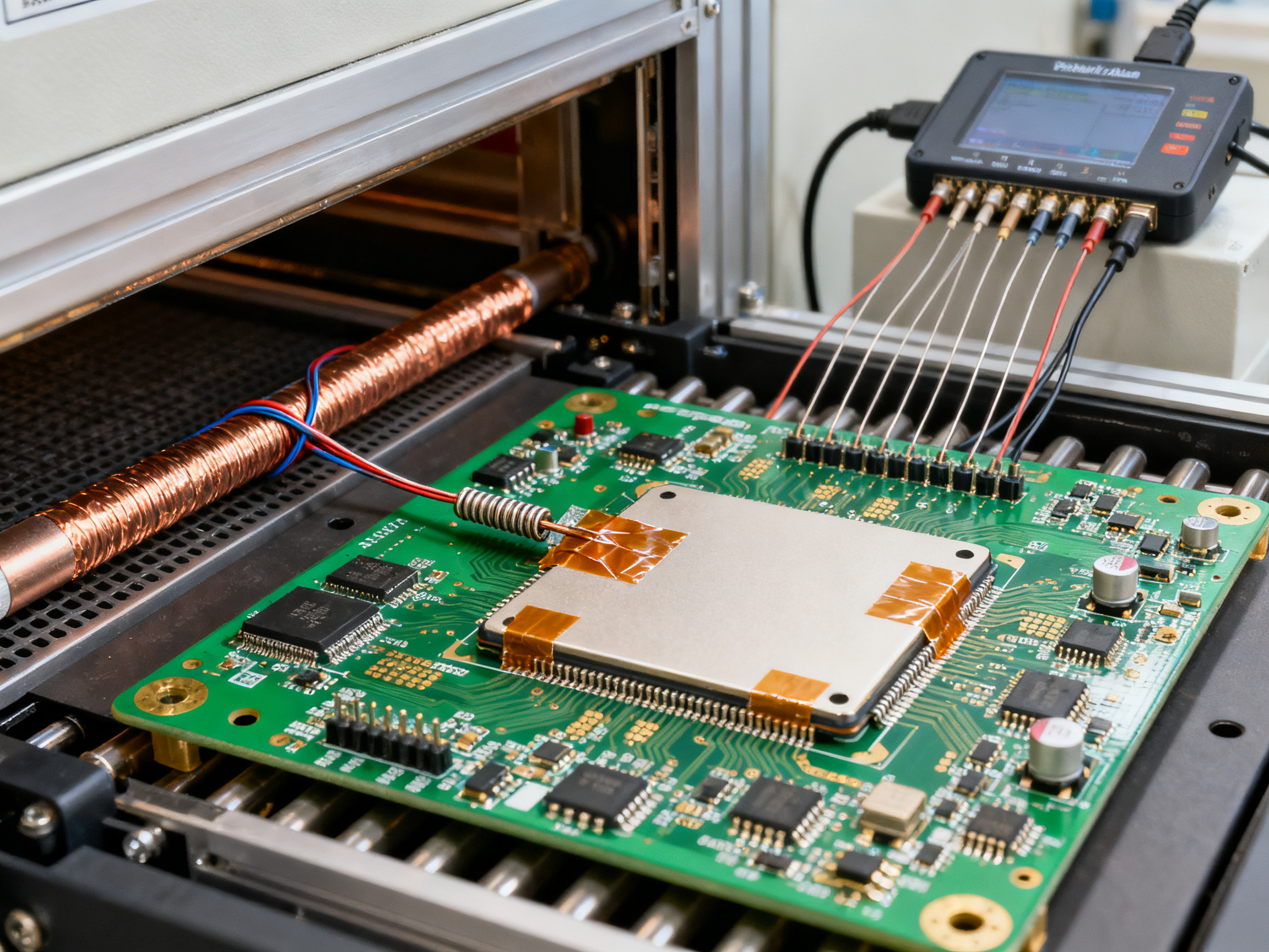
Attach the probe to the part that forms the joint
The most common profiling mistake is measuring air. Air in a preheat tunnel is hot, uniform, and tells you almost nothing about the board. A thermocouple clipped to the board surface on a six-layer assembly with heavy ground planes will read warmer than the actual joint, because the copper is pulling heat out of the probe.
Attach the thermocouple to the component body or the copper mass that matters: the QFN, the large BGA, the connector shell, or a heavy ground plane near the difficult joint. Use a fine-wire type K or type J probe, secure it with Kapton tape or a low-temperature adhesive, and keep the bead tight to the surface. Loose attachment reads late and reads noisy.
From Our Experience: We once profiled a line where every probe was taped to the board surface. The trace showed a tidy 155 °C soak. When we moved the probe to the body of a 48-pin QFN, the same recipe showed 118 °C at that component. The tunnel was fine. The measurement was lying, and the recipe had been copied from that lie for three years.
Read the trace, not the peak
A useful profile report shows the full ramp, the soak, and the temperature at the moment of solder contact. You want to see three numbers clearly:
- The ramp rate in °C per second, calculated from the linear portion of the curve
- The soak plateau and how long the board held inside roughly ±10 °C of target
- The temperature at solder contact, marked on the trace where the nozzle or wave touches down
If your profiler cannot trigger an event at solder contact, time the interval from the end of the tunnel to the nozzle and add the measured board temperature to the trace by hand. It is rough, but it is better than a peak number pulled out of context.
Build one recipe per board family
Mixed-model lines are where preheat discipline falls apart. A board family means shared construction: same layer count, same board thickness, similar copper coverage, similar component mix. Group them and give each family its own verified recipe. Changing the board from four layers to ten is not a setpoint tweak. It is a new recipe with a new profile run.
In practice, that means a saved recipe per family with the verified numbers attached, and a rule that a new family gets profiled before it runs in volume.
The production controls that keep it honest
Soldering lines are good at storing setpoints and bad at noticing drift. Set up these controls and the drift gets caught by the process instead of by your customers.
| Control | What it does | Why it matters |
|—|—|—|
| Recipe management in machine software | Stores a separate profile per board family with limits attached | Stops an operator loading a 10-layer recipe on a 4-layer board |
| SPC on preheat temperature | Charts board temperature at contact over time | Shows slow drift from filter fouling or heater ageing |
| Alarms on profile deviation | Stops the line or flags the board when temperature falls outside limits | Catches a cold board before it becomes a cold joint |
| Changeover documentation | Records which recipe ran on which part number | Makes the build record traceable during an audit |
| Scheduled re-verification | Re-profiles a board family on a fixed interval | Confirms the recipe still matches the machine and the material |
Statistical process control is worth explaining here, because the limits are not the same thing. Your specification limit comes from what the board can tolerate. Your control limit comes from the data. When the process is stable, the control limit sits inside the specification limit, and you get warning before you get scrap.
Pro Insight: If your preheat temperature chart shows a slow upward drift across a month, check the heater banks and the airflow filters before you touch the recipe. A dirty return duct and a degraded heater element look identical on the screen, and both are hardware faults, not process faults.
Also, log the parameters that an audit will ask for: board family, recipe name, board temperature at contact, ramp rate, soak time, flux type and lot, solder alloy and pot temperature, and the profile trace ID. For Class 3 and aerospace work, that trace belongs on the build record, not in somebody’s email folder.
[Photo placeholder: thermocouple attached to a QFN body on a populated PCB, secured with Kapton tape, with the profile report screenshot shown beside it]
Profile documentation checklist
- Probe type, attachment point, and photo of the attachment
- Ramp rate, soak time, and temperature at solder contact
- Hottest and coolest feature delta on the board
- Recipe name and machine settings used
- Joint quality result from the trial boards
- Re-verification date and sign-off
If you want to see how your boards actually land, send us a sample and your current recipe. We will run it through a wave soldering or integrated SMT setup and send back the trace, the temperatures, and the times in writing, so you can compare them side by side.## Preheating Defects and How to Diagnose Them
Defects do not arrive with a cause attached. A board comes off the line with a dull fillet and somebody opens a ticket titled “flux problem.” That ticket is where most preheat issues go to hide.
So let’s build the map. Symptom first, cause second, and then the diagnostic order that keeps you from chasing the wrong thing for two weeks.
The defect-to-cause table
| Defect you see | Preheat-related cause | Competing causes that look identical |
|—|—|—|
| Insufficient wetting, dull grainy fillet, poor hole fill | Board too cool at solder contact, soak too short to equalize thermal mass | Low pot temperature, short nozzle dwell, oxidised pad, contaminated hole |
| Solder balling and spatter around joints | Flux solvent not dried before hot contact, or moisture outgassing from a damp board | Too much flux, wrong flux type, spatter from nozzle gas, condensation on the line |
| Bridging and slumping on fine-pitch pins | Preheat overshoot, flux driven off so solder has nothing to work with | Solder pot too hot, long contact time, too little flux, no-clean residue |
| Icicles, webs, solder pulled off the pad | Excess heat plus long contact, molten solder over-flooding the joint | Nozzle mis-programmed, wave dynamics, board tilt |
| Component discoloration, lifted pads, cracked joints | Overshoot soak, thermal shock on exit, too-fast ramp | Package-specific limits, nozzle over-temperature, board material |
| Delamination or blistering on multilayer boards | Ramp too fast, trapped laminate moisture, repeated thermal cycling | Moisture pickup at assembly, bake requirement missed |
Notice how many rows have a twin in the right-hand column. Poor wetting can be a cold board or a cold pot. Balling can be wet flux or wet board. This is the whole reason a diagnostic order matters. You isolate one variable at a time, and you isolate preheat first because it is the cheapest to change and the most common to be wrong.
The diagnostic path
Step one, isolate preheat. Do not change anything else on the line. Add 15 to 30 seconds of soak in the final zone and drop the ramp slightly, then run a small batch. If the defect rate moves, you have your answer and you can refine from there. If it does not move, preheat was not the driver and you have saved yourself from a pointless recipe hunt.
Step two, check the thermocouple placement. This costs nothing and it catches a surprising share of cases. If the probe sits on the board surface while the real joint forms under a QFN body, your profile is describing a temperature that never existed at the joint. Move the probe, re-run, and compare.
Step three, look at the flux window. Log the interval from flux deposition to solder contact for the trial. If the board sits in the preheat zone longer than usual because someone slowed the conveyor last week, the flux may be flashing off before activation. That produces balling with a perfectly good preheat profile, and it will fool you if you only look at temperature.
Step four, then the rest. Pot or nozzle temperature, contact time, flux volume and type, solder alloy, wave or nozzle geometry, board design and hole size, contamination. Only now do you start swapping things.
From Our Experience: The field pattern we keep seeing on customer lines is “solder balling and insufficient wetting on QFN perimeters,” and it almost always traces back to an unverified board-top thermocouple position or a preheat zone still tuned for a 10-layer board running a 4-layer job. Not the paste. Not the nozzle.
What inspection can and cannot tell you
AOI reads the surface. It will find bridging, missing solder, obvious balling, and fillet shape problems on visible through-hole joints. That is genuinely useful, and it is where you start after a change.
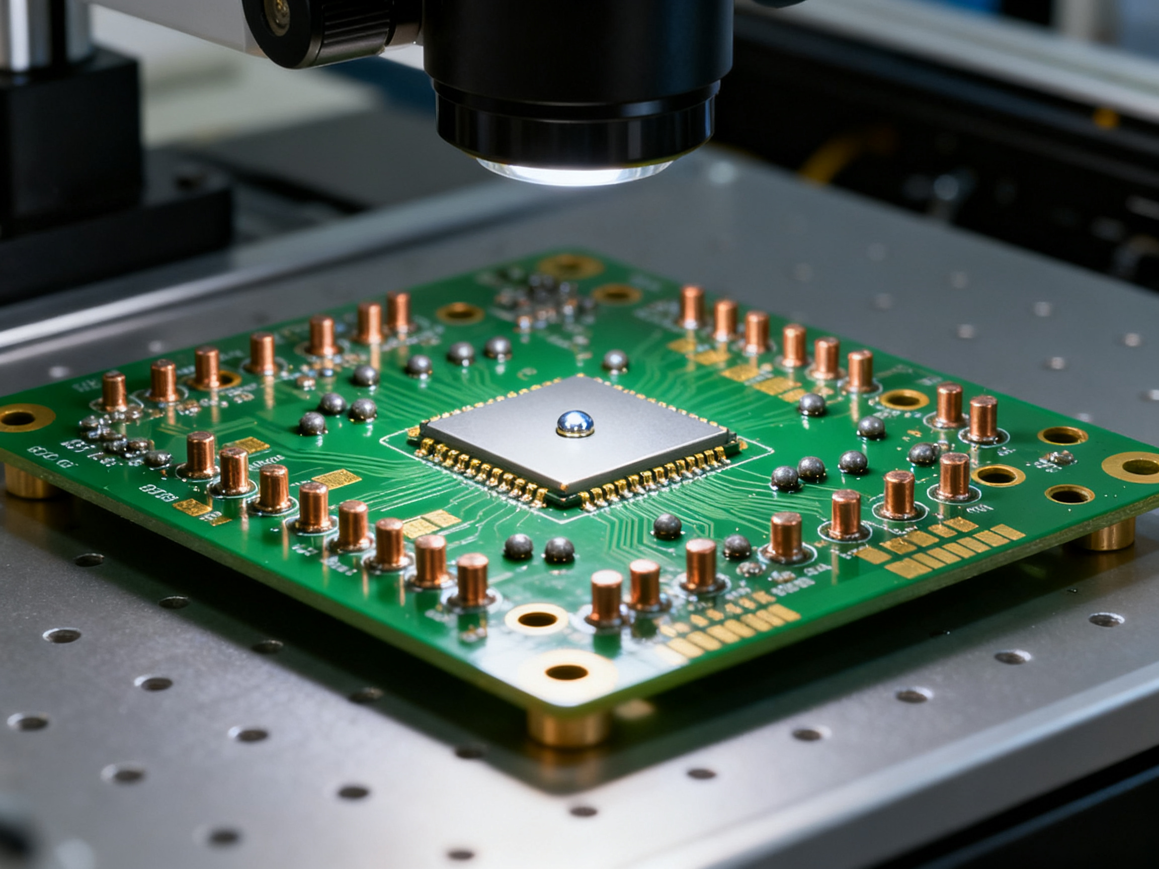
AOI will not tell you about hole fill. A barrel that is only 40 percent filled can look fine from above, because the solder surface is still smooth. Electrical test will find it as an open or a marginal resistance, but by then you are troubleshooting rather than diagnosing.
X-ray is the answer for hidden joints and buried fillets. For through-hole barrels on a double-sided assembly, X-ray shows the fill percentage directly. Use it when hole fill is the complaint, or when a joint is under a heat sink, a shield can, or a connector body.
Microsection is the last resort and the most convincing. When you need to prove a joint is sound before and after a change, cross-sections show the intermetallic layer, the fillet geometry, and the void. We ask for a cross-section when a customer needs evidence, not when we are still guessing.
Validating the fix with numbers
Do not validate a preheat change with a good-looking board. Validate it with defect rate data, before and after, on the same board family.
| Metric | Before change | After change |
|—|—|—|
| Joint defect PPM, X-ray plus AOI | [record your own] | [record your own] |
| First pass yield, electrical test | [record your own] | [record your own] |
| Board temperature at solder contact | [record your own] | [record your own] |
| Hottest to coolest feature delta | [record your own] | [record your own] |
Run enough boards for the sample to mean something, and hold the other variables still. If you changed soak time and the flux interval in the same week, you cannot say which one fixed it, and you will not be able to keep the fix.
And keep the profile trace attached to the validation lot. It is the only evidence that explains the number later, when someone asks why the recipe changed.
We will not hand you a universal defect percentage for preheat problems. There is no defensible industry-wide number, because preheat attribution gets tangled up with flux, alloy, and nozzle issues that nobody separates cleanly in public reporting. So measure your own line. Your own defect rate is the number that matters anyway.
If you want a before and after on your own boards, send us a sample and your current recipe. We will run it through a wave soldering or integrated SMT setup and give you the temperatures, times, and joint results in writing, so you can compare the two side by side.
[Visual placeholder: defect photo gallery with macro images of solder balling, insufficient fillet, and bridging, each labelled with its cause; a diagnostic flowchart graphic running left to right from symptom to isolated cause; and a small before and after defect rate bar chart for the validation table above.]## Optimizing Preheat for High-Density and Lead-Free Assemblies
The boards that break preheat assumptions are the ones with more than one kind of thermal mass on the same laminate. A 10-layer radar board with tall coax connectors. A server board with two large BGAs and forty small QFNs. A camera module with a bottom-exposed LED and a plastic housing that cannot take 200 °C. You cannot warm all of that from one side with one number.
So this section is about knowing when to stop tuning the tunnel.
The limits of one-sided heating
Preheat from the top can only do so much. It cannot heat what is behind a component body, under a shield can, or on the far side of a thick ground plane. Heat conducts down through the package, and by the time it reaches the joint the delta between the two has already done its damage.
When the coldest feature on your board sits more than about 20 °C below the hottest, you are past the point where profile tuning helps. The options are:
- Component-level heating. A hot-air knife aimed at the specific part, or a selective preheat head that tracks the joint.
- Dual-side heating. Convection from below, IR from above, or a mini-wave and top-side preheat combination.
- Nitrogen atmosphere. A nitrogen blanket over the solder contact reduces oxidation and gives you cleaner wetting on dense lead-free joints without adding thermal load.
- A mini-wave or dip system. When the thermal mass is genuinely large, immersing the bottom of the board transfers far more energy than a nozzle ever will.
- Carrier or pallet redesign. Sometimes the honest fix is balancing the copper so the board stops being its own heatsink.
We like the knife first because it is cheap and it is local. We like dual-side when the whole board is heavy. We like the mini-wave when the customer has already decided a nozzle line is the wrong tool for the part.
Lead-free changes the numbers
Moving from Sn63Pb37 to SAC305 tightens everything. The alloy’s liquidus sits near 217 °C, so the solder pot runs hotter, the board has to arrive hotter to close the gap, and the flux has more work to do before the alloy shows up.
Three practical consequences:
- Higher preheat target. 130 to 160 °C for most lead-free selective work, pushing toward 150 to 175 °C on heavy copper or 8-layer-plus builds.
- More sensitive to oxidation. SAC305 oxidizes faster than Sn63Pb37, and oxidized surfaces produce dull, non-wetting fillets that look exactly like cold joints. Nitrogen helps here.
- Flux that has to survive longer. Higher flux activation demand plus more heat means the drying window is tighter, not wider. If the flux flashes off before activation, you get balling, and the board temperature was never the problem.
We will not pretend there is a single right number for lead-free. But here is the table we actually start from, and we adjust after profiling.
| Board type | Preheat target at solder contact | Soak time (rule of thumb) | Method that works best |
|—|—|—|—|
| 2-layer, light copper, through-hole only | 130 to 150 °C | 15 to 25 s | Convection tunnel |
| 4-layer, moderate copper | 140 to 160 °C | 25 to 40 s | Convection or hybrid |
| 10-layer, heavy ground planes | 150 to 175 °C | 45 to 90 s | Hybrid IR plus convection, multi-zone |
| BGA-heavy mixed technology | 155 to 175 °C, measured on the BGA body | 45 to 90 s | Hybrid plus localized knife |
| Bottom-termination QFN or LED | 160 to 185 °C at the component | 30 to 60 s | Hot-air knife or dual-side |
| Plastic-heavy connector assemblies | 120 to 145 °C | 20 to 35 s | Convection, watch the connector body |
Soak times here are starting points, not rules. A 10-layer board with 70 percent copper coverage on the outer layers can need double the soak of a same-layer-count board with light copper, because the copper is holding and spreading the heat rather than letting the board equalize.
Pro Insight: On dense lead-free boards, measure the coldest feature before you commit to a soak time, not after. Attach the probe to the bottom-terminated QFN body, run the profile, and add soak until the component body, not the board surface, sits inside your window. The board surface will always look fine. The part is what forms the joint.
Class 3 work changes the documentation, not just the numbers
Automotive, aerospace, and defense programs live under IPC Class 3 workmanship expectations, and those assemblies face thermal cycling, vibration, shock, and long field service lives. A marginal fillet that passes on a general-purpose line can crack after a year of temperature swings.
What that means for preheat in practice:
- Repeatable profiles, not repeatable setpoints. Every board family gets a verified profile with the trace retained.
- Gentler ramps and gentler exit cooling. The joint you are protecting is the one already in the board.
- Documented evidence on the build record. Profile trace ID, board temperature at contact, ramp rate, soak time, flux lot, alloy, and pot temperature.
Standards like IPC J-STD-001 and IPC-A-610 set acceptance criteria for finished joints rather than prescribing a preheat profile, so nobody can hand you a compliant preheat temperature. Qualification lives with you and your customer. Where a program calls for additional reliability evidence, thermal cycling and vibration requirements get layered on top of the workmanship standard, and those come from the customer or program, not from a generic preheat rule.
What we would do first on a high-density line
Honestly? Profile it properly, then stop tuning and add a heating source. Run a trial with a thermocouple on the coldest component, look at the hottest-to-coldest delta, and compare it against the table above. If the delta is under about 10 °C, keep tuning the tunnel. If it is above 20 °C, no setpoint will save you. That single measurement usually answers the question in an afternoon, and it saves months.
Ready to see how these setups behave on your own dense boards? Send us a sample and your current recipe, and we will run it through one of our wave soldering or integrated SMT setups so you can compare the profiles side by side, with temperatures and times in writing.## Best-Practice Checklist and Implementation Roadmap
Here is the short version you can run this week. Five steps, in order, and most of them cost nothing but a shift of attention.
The 5-Step Checklist
- Profile one board family this week. Clip a fine-wire thermocouple to the coldest, heaviest component on the board. Not the board surface. Run it through your tunnel and write down the ramp rate, the soak time, and the temperature at the exact moment of solder contact.
- Set ramp and soak from what you measured. Keep the bulk ramp between 1 and 2.5 °C per second for most boards, then add soak until the component body sits inside your window. Board surface readings lie, so trust the part.
- Verify, not assume. Check the hottest to coldest delta on the board. Under 10 °C and your tunnel is doing its job. Over 20 °C and no setpoint will fix it; you need another heat source.
- Document the recipe. Save one verified recipe per board family. Record the trace ID, the probe type, the attachment point, and a photo of that attachment.
- Watch it in production. Chart board temperature at contact over time. When the chart drifts, the hardware moved, not the recipe.
Symptom, Check, Action
| Symptom | First check | Action |
|—|—|—|
| Cold joints, poor wetting | Thermocouple placement | Move the probe to the component body and re-profile |
| Solder balling on QFN perimeters | Flux to solder contact interval | Log the interval, then adjust conveyor speed or preheat length |
| One cold corner or connector | Hottest to coolest delta | Add a hot-air knife or switch to dual-side heating |
| Discoloration, lifted pads | Exit temperature and cooling | Reduce soak, slow the ramp, gentler exit cooling |
| Profile drifts over weeks | Filters and heater banks | Clean the return duct, check the elements, do not touch the recipe |
| Recipe copied to a new board | Layer count and copper coverage | Treat any new construction as a new recipe and re-profile |
Fitting Preheat Into the Rest of the Line
Preheat does not live on its own island. It shares the conveyor with the flux dispenser and the nozzle, and it shares your data with everything downstream.
In practice, that means the preheat zone length and the number of zones decide your dwell time, so a machine with three zones behaves differently from one with six even at the same setpoint. Speed changes on the conveyor move your flux interval, which changes your balling risk. And your inspection step needs to know which recipe ran, or your AOI data cannot be tied back to a profile.
The good news is that most modern machines and profilers can pass their data along. The recipe name, board temperature at contact, ramp rate, soak time, flux lot, alloy, and pot temperature can all be logged into MES and SPC reporting. What you want on a dashboard is simple: board temperature at contact per board family, plotted over time, with alarm limits around it. That single chart catches filter fouling, heater ageing, and an operator loading the wrong recipe, long before the customer does.
For legacy lines, you do not need to replace the machine to get most of this. Add a profiler, add a thermocouple fixture, and set the recipe inside the existing machine software. Retrofitting measurement and recipe control is usually cheaper than retrofitting heat.
What It Is Worth
We will not hand you an industry-wide savings figure, because no defensible public number exists for preheat-attributed defect reduction. Measure your own line instead. But the line items are real:
- Fewer defects. Cold joints and balling are rework labor, plus scrapped boards, plus customer returns.
- Less rework and less flux waste. Running a hotter board or a longer soak to chase a cold joint burns flux and adds time for nothing.
- Lower labor per board. A profile that holds does not need a technician walking the line with a thermometer.
- Faster changeover. One saved recipe per board family means fewer profile runs at every product change. That is where the throughput hides.
Here is the honest arithmetic. If you find 30 boards a day with cold joints, and each one takes 12 minutes of rework plus the material, that is real money disappearing every shift. You do not need a new preheater to stop it. You need the measurement.
Expert Tip: If you can only do one thing from this list, do step one. Put a thermocouple on the coldest component, run one board, and look at the number. Almost every preheat mystery we have worked on ended with someone saying, “Oh. It was never that hot.”
Want to compare this against your current setup? Send us a sample board and your existing recipe, and we will run it through one of our wave soldering or integrated SMT setups so you can compare the profiles side by side, with temperatures and times in writing.## Conclusion: The Expert Take on Preheat Discipline
The thing worth remembering from all of this is short: PCB preheating for selective soldering is a controlled process with numbers attached, not a dial somebody sets by feel on a Tuesday morning. The board has to arrive at solder contact already at temperature, measured at the component that actually forms the joint. Everything else in this guide is just detail on how to prove that.
Key takeaways:
- Preheat runs after flux and before solder contact. It is the only heat input you control before the molten alloy arrives.
- For SAC305 lead-free work, most selective lines land on 130 to 160 °C at the board, with 150 to 175 °C for heavy copper and 8-layer-plus builds. Leaded Sn63Pb37 usually sits lower, around 110 to 140 °C.
- Board surface readings lie. Clip the thermocouple to the component body, and treat 10 to 15 seconds of final dwell as a starting point.
- A bulk ramp of 1 to 2.5 °C per second protects packages and laminates without wasting line time.
- If the hottest-to-coldest delta on the board exceeds about 20 °C, no setpoint will save you. Add a heat source or change the geometry.
- Defect tickets titled “flux problem” are worth re-reading as preheat problems first, because preheat is cheap to change and wrong surprisingly often.
Questions to ask your selective soldering vendor
- Can the preheat tunnel hold a separate profile per board family, with limits attached inside the machine software?
- What is the ramp rate and soak time the tunnel can actually deliver at line speed, in writing?
- How many zones are available, and can the last zone be brought close to target to buy soak without overshoot?
- Is there a hybrid IR plus convection option, and how is the balance tuned for shadowed areas?
- Does the machine log board temperature at solder contact, or only the setpoint?
- Can recipe data and profile traces be exported for SPC and MES?
- How is the flux-to-solder interval controlled when conveyor speed changes?
- What cooling control exists at the exit, and how is exit temperature verified?
- Does the platform support dual-side heating or an integrated hot-air knife for bottom-terminated parts?
- Can preheat capability be evaluated as part of a full line, from flux dispense through inspection, or only as a standalone module?
That last point matters more than most buyers expect. Preheat capability is a property of the whole machine, meaning tunnel hardware, airflow, software, and conveyor speed all together. A preheat zone that looks good on a spec sheet but cannot hold a recipe per board family will not save your line. Evaluate it as one part of a complete selective soldering or wave soldering solution, and demand the profile data behind the claims.
Want to compare profiles on your own boards? Send us a sample and your current recipe, and we will run it through one of our wave soldering or integrated SMT setups so you can see the difference side by side, with temperatures and times in writing.