You can prevent defects and maintain clean SMT assemblies by focusing on critical factors. Begin with a robust PCB design and choose high-quality materials. Use precise equipment calibration and enforce strict process control. Cleanliness at every stage ensures reliable results. Pay attention to every detail. Consistent practices and regular monitoring help you prevent defects and deliver flawless assemblies.
Key Takeaways
-
Begin with a robust PCB design and select high-quality materials to minimize defects.
-
Regularly calibrate equipment like pick-and-place machines and reflow ovens to ensure accuracy.
-
Maintain clean workspaces and follow cleanroom protocols to prevent contamination.
-
Control the assembly process carefully, including solder paste volume and temperature profiles.
-
Train your staff well and use thorough inspection methods to catch and fix defects early.
SMT Defects

Soldering Issues
You encounter soldering issues more often than any other defect in SMT assembly. Solder paste printing errors account for up to 90% of soldering faults. Common problems include solder bridges, open solder joints, and insufficient solder connections. These defects usually result from excess solder paste, poor stencil design, or misalignment during printing. You also see problems when equipment calibration is off or when contamination affects the soldering process.
Tip: Always check your solder paste volume and stencil alignment before starting production.
|
Defect Type |
Percentage of Soldering Defects |
|---|---|
|
Open Solder Joints |
|
|
Solder Shorts (Bridges) |
|
|
Component Misalignment |
20% |
Misalignment
Misalignment happens when components do not sit correctly on the PCB pads. You may notice this defect due to mechanical issues in pick-and-place machines, nozzle wear, or inaccurate head movement. Material problems such as warped boards, pad size inconsistencies, and surface contamination also contribute. Environmental factors like temperature changes and humidity can cause components to shift. Tombstoning, where a component stands upright, often results from uneven heating during reflow.
-
Warped or contaminated boards
-
Incorrect placement pressure
-
Temperature and humidity fluctuations
Contamination
Contamination affects solderability and reliability. You face contamination from dust, oils, and residues left on PCB surfaces or components. Poor cleaning practices and improper handling introduce foreign particles. These contaminants prevent proper solder wetting and can lead to open joints or weak connections. You must maintain clean workspaces and use proper storage to reduce contamination risks.
Electrical Failures
Electrical failures in SMT assemblies stem from several root causes. You see welding failures, solder bridging, and insufficient solder joints most frequently. Poor quality components, incorrect reflow profiles, and improper maintenance lead to these problems. Non-wetting failures occur when PCB surfaces are not prepared well or stored for too long. Temperature extremes and rapid changes cause cracks and joint failures.
|
Electrical Failure |
Root Cause |
|---|---|
|
Solder bridging |
Excess solder paste, stencil misalignment |
|
Insufficient solder joints |
Clogged stencil, poor coplanarity, PCB defects |
|
Non-wetting failures |
Poor surface prep, plating deterioration |
|
Temperature-related failures |
Rapid temperature changes, extremes |
Note: Regular inspection and process control help you catch these defects early and maintain assembly quality.
Prevent Defects
Design Optimization
You can prevent defects by starting with robust design optimization. Focus on pad geometry, stencil aperture, and PCB layout. Use symmetrical pads and follow IPC standards to ensure even solder wetting and heating. Select the right surface finish, such as ENIG or immersion tin, for uniform solderability. Refine stencil design and control paste thickness to avoid uneven solder volume. Simulate heat distribution and collaborate with your manufacturer to identify potential issues before production.
Tip: Adjust reflow profiles and balance thermal mass to minimize tombstoning and solder bridging.
Empirical studies show that stencil printing accounts for up to 70% of soldering defects. Optimizing stencil parameters—such as aperture area, thickness, printing speed, and squeegee pressure—statistically reduces defect rates and improves first-pass yield. Use statistical control processes and AI-driven modeling to enhance printing consistency and reliability.
-
Optimize pad and trace design
-
Select appropriate stencil thickness
-
Simulate and test heat distribution
-
Collaborate with manufacturers for DFM checks
Material Selection
Material selection plays a critical role in your ability to prevent defects. Choose solder paste with the correct particle size for your application. Finer particles (Type 4 or Type 5) work best for fine-pitch components and reduce bridging, tombstoning, and voids. Ensure solder paste compatibility with your components and flux to avoid intermetallic formation and thermal stress.
-
Store solder paste in cold, dry conditions
-
Use high-activated solder paste for better wetting
-
Inspect components for oxidation and moisture before assembly
Studies indicate that selecting the right solder paste particle size can reduce defect rates by up to 30% in high-density assemblies. Evaluate solder paste for viscosity, printability, slump, solder balling, and wetting ability. Maintain safety stock and monitor batch consistency to avoid variability.
Note: Proper storage and handling of solder paste and components help you prevent defects that are difficult to fix later.
Equipment Calibration
You must calibrate your equipment regularly to prevent defects and maintain optimal performance. Calibration ensures accurate component placement and consistent solder paste deposition. Skilled technicians should perform initial and periodic recalibrations as part of your preventive maintenance schedule.
-
Monthly: Inspect alignment and perform thorough checks
-
Daily: Monitor equipment status, but full calibration is not required
|
Resulting SMT Defects |
Prevention Methods |
|
|---|---|---|
|
Pick-and-Place Machine Calibration |
Component misalignment, misplacement |
Regular calibration, vision alignment, and operator training |
|
Stencil Printer Calibration |
Solder paste misprinting, inconsistent paste |
Regular cleaning, proper calibration |
|
Reflow Oven Calibration |
Cold solder joints, tombstoning, thermal defects |
Precise thermal profiling, oven maintenance, temperature monitoring |
Regular calibration and maintenance help you prevent defects such as misalignment, cold solder joints, and thermal failures.
Process Control
Process control is essential if you want to prevent defects and maximize yield. Optimize your reflow profile to ensure even heating and cooling. Use advanced thermal profiling tools to maintain peak temperatures for lead-free soldering. Monitor oven temperature uniformity within ±5°C and adjust conveyor speed for different board sizes.
-
Control solder paste volume and avoid overheating
-
Balance pad sizes and paste deposits
-
Maintain workshop temperature (18°C–28°C) and humidity (40%–70%)
-
Inspect PCB surfaces for deformation, oxidation, and scratches
Automated prediction tools and AI-based optimization methods help you find robust profiles for multiple products. These improvements minimize defects, improve solder joint quality, and increase reliability.
Callout: Consistent process control reduces solder bridging, tombstoning, and misalignment, helping you prevent defects across all stages of SMT assembly.
Training
Training your personnel is one of the most effective ways to prevent defects. Comprehensive training programs teach operators fundamental soldering techniques and defect classification. Use hands-on courses and Six Sigma methodologies to improve accuracy and repeatability in defect detection.
-
Schedule regular training and feedback sessions
-
Certify operators to IPC-A-610 standards
-
Use KPIs and quality metrics to track performance
|
Role of Training |
Measurable Outcome |
|
|---|---|---|
|
First Pass Yield (FPY) |
Training on inspection tools and standards improves initial quality. |
Higher FPY, fewer defects and rework. |
|
Defects Per Million Opp. |
Skilled operators reduce defects through better process control. |
Lower DPMO, improved precision. |
|
Customer Return Rates |
Training enables effective CAPA and quality assurance practices. |
Reduced returns, higher reliability. |
|
Certification (IPC-A-610) |
Training and certification ensure consistent inspection standards. |
Standardized checks, reduced errors. |
Regular training reduces downtime, increases productivity, and lowers defect rates. Well-trained operators adapt quickly to new technology and maintain high output.
Tip: Continuous training and certification help you prevent defects and maintain consistent quality in SMT assemblies.
Assembly Best Practices
Cleanroom Protocols
You must control your assembly environment to prevent contamination and defects. Cleanrooms in SMT manufacturing follow ISO 14644-1 standards, which regulate airborne particles, temperature, humidity, and pressure. Most SMT cleanrooms operate at ISO Class 7 or 8, maintaining strict limits on particle counts and using rapid air exchange systems.
|
ISO Class |
Max Particle Count (0.5μm) |
Air Change Rate (per hour) |
Typical Gowning |
|---|---|---|---|
|
ISO 7 |
10,000 |
60–120 |
Smock, shoe covers, hair cover |
|
ISO 8 |
35,200,000 |
10–25 |
Hair net, basic lab attire |
You should wear ESD aprons, gloves, and hairnets, and follow hygiene protocols to minimize contamination. Cleanroom layouts separate storage, assembly, and inspection zones. By following these protocols, you reduce airborne particles and lower the risk of random, hard-to-diagnose defects, which improves long-term reliability.
Tip: Regular cleaning and scheduled audits keep your cleanroom within required standards and support high-quality assembly.
Storage And Handling
Proper storage and handling protect your components from moisture and static damage. Always use anti-static bags and conductive containers to prevent static buildup. Store moisture-sensitive devices in dry cabinets with humidity below 10%. If you lack controlled cabinets, use sealed moisture barrier bags with desiccants and humidity indicators.
-
Monitor storage areas with humidity and temperature sensors.
-
Inspect components for corrosion or damage before assembly.
Improper storage can degrade plating and finishes, reducing solderability and increasing defect rates. You should follow JEDEC MSL ratings and pre-bake sensitive components if needed. These steps preserve solderability and prevent costly rework.
ESD Protection
You must control static electricity to prevent latent defects in your assemblies. Equip workstations with static-dissipative mats and ESD-safe tools. Ground yourself with wrist or heel straps and wear ESD-protective clothing. Maintain humidity around 50% RH and use air ionizers to neutralize static charges.
-
Store and transport components in static shielding bags.
-
Train staff on ESD risks and handling procedures.
-
Test ESD control systems regularly.
Latent ESD damage causes most ESD-related failures and often escapes detection during inspection. Effective ESD protection ensures long-term reliability and reduces early failures.
Maintenance
Consistent maintenance keeps your equipment running smoothly and prevents defects. Clean feeders, nozzles, and conveyor belts daily to avoid debris buildup. Lubricate moving parts weekly and calibrate machine settings. Deep clean vision systems and perform accuracy tests monthly.
|
Frequency |
Key Tasks |
|---|---|
|
Daily |
Clean feeders, nozzles, inspect conveyors, and verify the vision system |
|
Weekly |
Lubricate parts, inspect for wear, calibrate settings |
|
Monthly |
Deep clean, performance tests, review maintenance logs |
Predictive maintenance and regular checks help you spot issues early, reduce downtime, and maintain high yield. When you involve your team in maintenance routines, you improve uptime and reduce defect rates across your SMT line.
Inspection And Troubleshooting

Visual Inspection
You rely on manual visual inspection (MVI) as a vital first step in quality control. Skilled technicians use magnification tools and angled lighting to spot surface-level defects such as cold solder joints, solder bridges, and misaligned components. Proper lighting reveals subtle issues that machines may miss. Manual inspection works best as a final check, catching minor flaws after automated systems finish. However, you cannot detect hidden or internal defects with this method alone.
Tip: Combine visual inspection with automated systems for the most thorough defect detection.
AOI
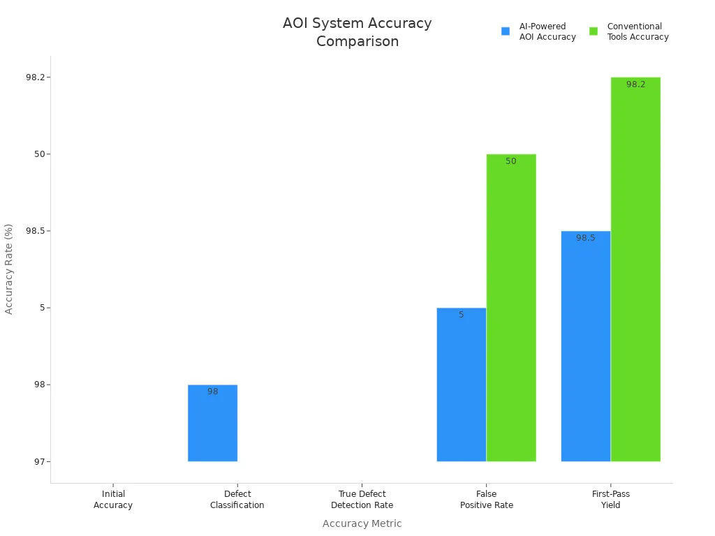
Automated Optical Inspection (AOI) uses high-resolution cameras and advanced image processing to scan your assemblies quickly. AOI excels at finding missing components, soldering defects, and misalignments. Modern AOI systems achieve defect detection rates above 95%, ensuring only quality boards move forward. AI-powered AOI further boosts accuracy, reducing false positives and improving first-pass yield.
|
Metric |
Conventional Tools Accuracy |
|
|---|---|---|
|
Initial Accuracy |
97% |
N/A |
|
Defect Classification |
97–99% |
Lower (unspecified) |
|
True Defect Detection Rate |
>97% |
Lower |
|
False Positive Rate |
4–6% |
~50% |
|
First-Pass Yield |
~98.5% |
~98.2% |

You benefit from AOI’s speed and consistency, but remember it cannot see beneath components.
X-Ray
X-ray inspection (AXI) gives you a non-destructive look inside your assemblies. You can detect hidden solder joint defects under BGAs, QFNs, and multilayer PCBs—problems that AOI and visual checks cannot find. AXI reveals solder voids, cracks, and missing solder balls, which are critical for high-reliability products in aerospace or medical fields. Although X-ray inspection takes longer and costs more, it ensures you catch internal flaws before they cause failures.
-
AXI inspects hidden joints and internal layers.
-
AOI checks surface defects quickly.
-
Combining both methods gives you the best coverage.
Root Cause Analysis
When you find defects, you must identify their root causes to prevent recurrence. Most SMT defects come from common variations like soldering profile changes, ambient temperature shifts, or material inconsistencies. Sometimes, special causes such as equipment malfunctions or operator errors create unique problems. You address common causes by optimizing processes and maintaining strict controls. For special causes, you target corrective actions—like recalibrating machines or retraining staff.
-
Use high-precision placement and regular calibration to reduce misalignment.
-
Monitor solder paste application and reflow profiles to prevent bridging and cold joints.
-
Standardize components and inspect incoming materials for consistency.
Note: Effective troubleshooting combines inspection data with process analysis, helping you improve quality and reduce costly rework.
You achieve clean SMT assemblies when you focus on process control, staff training, and thorough inspection.
-
Use integrated systems and multi-level inspection gates to prevent defects early and boost first-pass yield.
-
Apply best practices like precise placement, optimized solder paste, and automated reflow ovens for long-term reliability.
Consistent process review and adherence to industry standards help you maintain quality and reduce costly failures.
FAQ
What is the most common cause of SMT defects?
You often see solder paste printing errors as the main cause. These errors lead to solder bridges, open joints, and misalignment.
Tip: Always check stencil alignment and paste volume before starting production.
How can you keep your SMT assembly clean?
You should use cleanroom protocols, wear ESD-safe clothing, and clean surfaces regularly. Store components in sealed containers.
-
Clean workstations daily
-
Use air filtration systems
-
Inspect for dust and residue
Why does equipment calibration matter in SMT?
Calibration ensures accurate placement and consistent soldering. Uncalibrated machines cause misalignment, poor solder joints, and higher defect rates.
|
Task |
Frequency |
|---|---|
|
Pick-and-place |
Weekly |
|
Stencil printer |
Monthly |
|
Reflow oven |
Monthly |
How do you prevent ESD damage during assembly?
You must ground yourself with wrist straps and use ESD mats. Store parts in static-shielding bags.
Note: Regularly test your ESD protection systems to ensure reliability.
