
Published: October 23, 2026
Last updated: October 23, 2026
Reading Time: 14 minutes
2. Introduction: Choosing the Right Reflow Method
Two ways to melt solder, one very different job.
A reflow station blows hot air at a single spot on a board. It’s the tool you reach for when a capacitor fell off, when a QFN pad needs reworked, or when you’re building a prototype on your kitchen table at 11pm. A reflow oven does the opposite. It moves a fully assembled PCB through a programmed temperature profile, heating the whole board the same way every time.
That difference shows up in the failure list. Common defects like bridging, solder balls, tombstoning, voids, head-in-pillow, and component shift come from a mix of paste volume, stencil design, placement accuracy, board thermal mass, and the thermal profile itself. Localized heating adds temperature gradients near adjacent parts and depends heavily on the operator. Oven heating adds board-wide excursions when a recipe is wrong. Neither one saves you on its own, and the IPC/JEDEC standards that define workmanship say as much.
One number worth holding onto: common lead-free SAC305 solder melts at roughly 217 to 220 C, while SnBi alloys melt near 138 to 140 C. That’s why “reflow temperature” is a range tied to your paste, not a single dial setting.
[Diagram: localized hot-air reflow station on the left, multi-zone conveyor reflow oven on the right, with a labeled temperature curve for each.]
Here’s the plan. We’ll cover how reflow works mechanically, what a reflow station really is, what a reflow oven really is, how to build a safe thermal profile, how to reflow a board with each method, the defects each choice tends to cause, and a cost per conforming board framework for picking one.
Which one you need depends less on what you want to build than on how much you build. Let’s dig in.## 3. About the Author
Note to the publisher: an author name, photo, and profile link were not supplied for this piece, so no byline, credentials, or reviewer line appears here. Add them only after a named author with verifiable SMT, soldering-process, or equipment-selection experience is confirmed. Please do not publish a reviewer line without documented identity, affiliation, and review date.
This article was written from published technical sources rather than a single named author. Core process details, defect definitions, and acceptance criteria come from IPC and JEDEC standards documents, component manufacturer assembly guidelines, and application notes on BGA and QFN rework profiling.
How the work was done: source documents were gathered and cross-checked, and no claim of first-hand factory experience, measured yield gain, or payback period appears anywhere in the text. Where independent 2026 pricing or production yield comparisons could not be verified, the article says so plainly instead of filling the gap with an estimate.
Any equipment recommendations, thermal profiles, and defect guidance here are educational and general. They do not replace manufacturer instructions, solder paste datasheets, your own site procedures, or a qualified engineering review. Validate the actual product, paste, and equipment before running production.## 2. Reflow Stations vs. Reflow Ovens: Which Way Should You Heat the Board?
Once the paste is printed and the components are placed, the assembly needs a controlled heat cycle. Two tools perform that job: a reflow station heats one board at a time, while a reflow oven moves a board or panel through a heated chamber. They use the same reflow physics, but they suit different production volumes, board sizes, and budgets.
Reflow Stations: Direct Heating for Small-Scale Work
A reflow station is essentially a heating platform built into a controlled cycle. Depending on the design, the board may be heated from below, exposed to infrared radiation, or heated with a combination of bottom and top heat. Most benchtop stations use a hot plate or infrared heater with a thermocouple attached to the board.
The station follows the same basic profile as an oven:
- Ramp the board toward the preheat temperature.
- Hold it in the soak region long enough to activate the flux.
- Move above the solder alloy’s liquidus temperature.
- Dwell briefly at peak temperature.
- Cool the assembly before removing it.
The main advantage is simplicity. A station is relatively inexpensive, quick to set up, and convenient for prototypes, repair work, and small production runs. It can also be easier to inspect because the entire board remains visible during heating.
That convenience comes with limitations. Air temperature is not always the same as the temperature of the solder joint. The metal, board laminate, component package, and fixture can all heat at different rates. A hot plate may create a strong thermal gradient, while infrared heating can expose one region of the board to more radiation than another. Large boards and densely populated assemblies are therefore more difficult to profile accurately on a simple station.
A thermocouple helps by measuring the temperature at a specific point, but one point is not the whole board. Good practice is to attach the sensor near a representative component or pad without obstructing the optical view, and to verify that the profile remains repeatable after every major process change.
Reflow Ovens: Controlled Heating for Production
A reflow oven is a conveyorized or batch-heating system designed to create a repeatable thermal environment. The board moves through separate preheat, soak, reflow, and cooling zones, or remains stationary while the chamber follows a programmed cycle. Forced air, infrared elements, or a combination of both provide the heat.
Ovens offer several advantages over single-board stations:
- More uniform heating across large boards
- Better control of airflow and temperature distribution
- Higher throughput in production
- Capacity for trays, panels, or multiple boards
- Easier integration with conveyor, inspection, and traceability systems
The tradeoff is cost and complexity. An oven requires more space, more maintenance, and a more involved setup. Operators must select the correct program, verify airflow, calibrate sensors, and ensure that boards are positioned consistently within the heating zones.
For low- and medium-volume manufacturing, a small conveyor oven may be the practical compromise. For high-volume assembly, a profile-controlled oven is usually essential because a slightly inconsistent thermal cycle can produce defects across an entire production run.
Hot Plates, Infrared, and Convection Heating
The three most common heating methods are often confused with one another, but they work differently.
Hot-plate heating transfers energy through direct contact. The board sits on a heated platform, so heat travels upward through the PCB and reaches the solder joints by conduction. This method is straightforward and inexpensive, but temperature control depends heavily on board size, copper coverage, and the thermal mass of the components.
Infrared heating sends radiant energy toward the board. Components can absorb radiation differently from the PCB, producing localized hot spots. Infrared systems often heat quickly and are useful for specialized processes, but their profiles must be carefully validated.
Convection heating moves heated air across the assembly. Forced airflow can distribute heat more evenly and cool the board rapidly, but it also makes proper sealing, airflow balance, and exhaust control important.
Many production ovens combine infrared and convection. This allows rapid heating, controlled cooling, and more uniform temperature distribution than a single heating method can provide.
Why the Profile Must Be Measured
A station or oven does not create a reliable solder joint simply by reaching a chosen temperature. The profile must be measured at the board level and checked against the requirements of the solder paste, components, PCB materials, and package types.
A typical profile check records:
- Ramp-up rate
- Time spent above the solder alloy’s liquidus temperature
- Peak temperature
- Time spent within the soak region
- Cooling rate
- Temperature difference across the board
This is why a recipe in the oven’s controller is only a starting point. The actual profile should be verified with a profile tester or a calibrated board-and-thermocouple setup. The test board should resemble the real assembly in materials, size, copper coverage, component loading, and placement because those factors determine how quickly it heats and cools.
The paste manufacturer’s recommended profile should take priority over generic settings. Its limits may specify a maximum ramp rate, a minimum soak time, a peak-temperature range, and a maximum time above liquidus. Staying outside any of those limits can cause problems such as insufficient flux activation, solder-ball formation, weak joints, component damage, or excessive intermetallic growth.
How to Choose
Choose a reflow station when you are prototyping, repairing boards, manually assembling a small number of assemblies, or learning the process. A controlled hot-plate station is usually sufficient for simple boards, while an infrared station offers fast heating for appropriate applications.
Choose a reflow oven when you need repeatable production cycles, larger boards, panel assembly, or integration with an automated line. The additional cost is justified when profile consistency and throughput matter more than a low purchase price or a small footprint.
Whichever tool you use, remember that the controller displays the process, while the solder joint experiences the board. Validate the real thermal profile on a representative assembly, document the settings, and recheck them whenever the paste, board design, component mix, or fixture changes.
Coming up next: the profile itself—how to turn time and temperature into a solder joint you can trust.## 2. What Is a Reflow Station?
A solder reflow station is bench equipment that melts solder with controlled heat so components can be installed, removed, or replaced. Depending on the design, the heat arrives as hot air from a handheld nozzle, as infrared radiation, or as a combination of bottom preheat and top heating. That is what reflow soldering is used for in small-scale work: putting a part onto a board that has already had solder paste printed, and doing it again years later when that part fails.
Think of the three common shapes:
- Hot air reflow station. A heating element and fan push hot air through a handpiece nozzle. Fast, common, and cheap. This is the classic bench tool.
- Infrared reflow station. A lamp or emitter heats the board from above, often with a preheater below. Quick ramp, but light can hit components and pads unevenly.
- Bottom-heated or hot plate station. The board rests on a controlled platform and heat travels up through the laminate. Very controllable, slow, and hard on large boards.
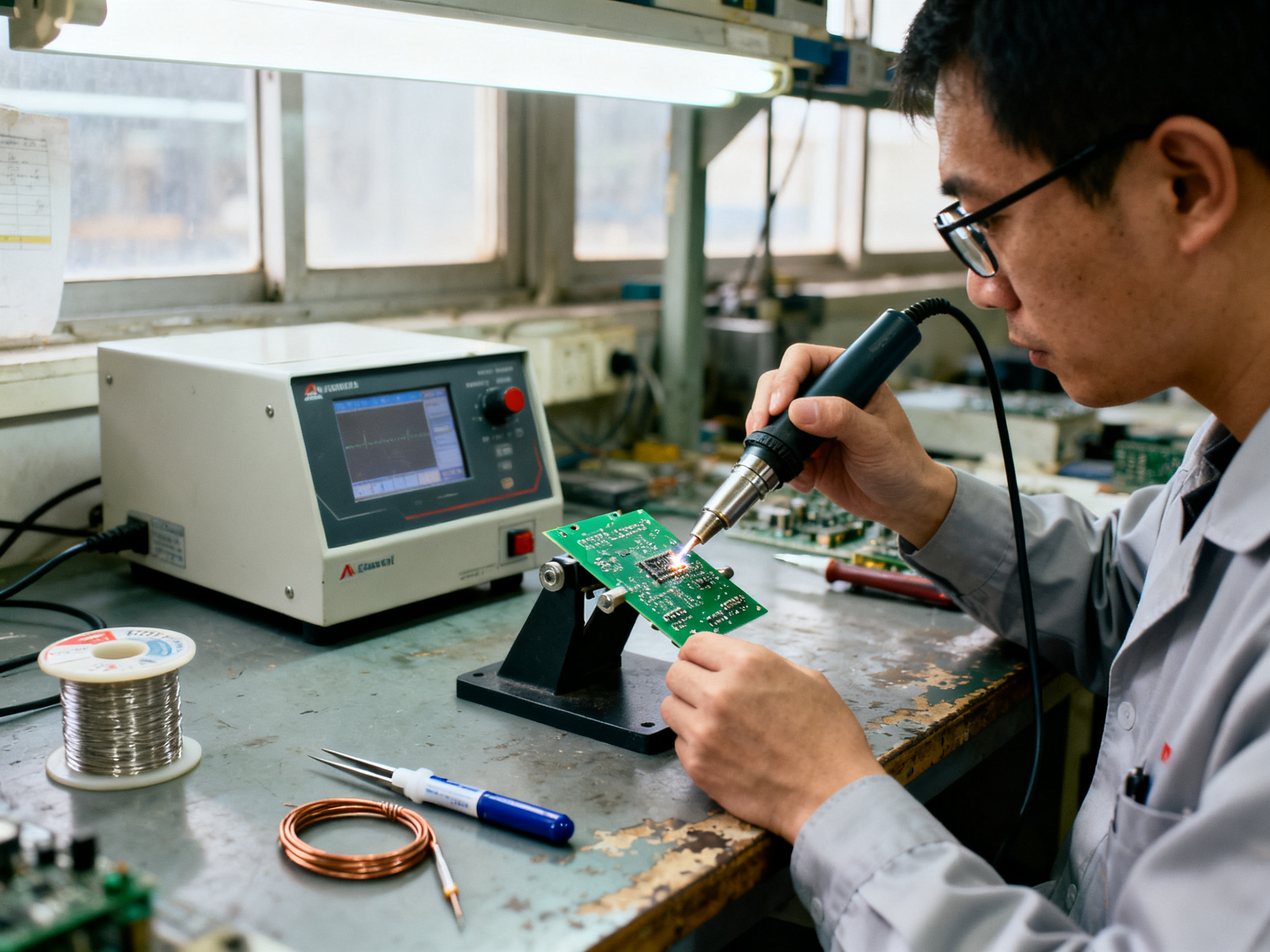
What sits on the bench is more than a hot nozzle. A useful station has an airflow control, a temperature setpoint, a preheater, a PCB holder with a few tilt positions, and a thermocouple input so you can log what the board actually sees. Vacuum pickup is common on rework stations so you can lift a part without sliding it sideways. Heated-air rework stations go further: they add shaped nozzles, board support arms, preheat, and often stored profiles for repeatable work on BGA and QFN packages.
Expert Tip: The number on the station display is air temperature, not joint temperature. Copper weight, board thickness, package mass, nozzle distance, and airflow all shift the real result. Attach a thermocouple at or near a representative pad, profile the workpiece, and treat the display as a starting point rather than proof.
Terminology box: four tools people mix up
| Tool | What it actually does | Typical job |
| — | — | — |
| Reflow station | Heats a whole small board or a single area to melt paste | Prototyping, new builds, rework |
| Rework station | Hot air plus nozzles, pickup, and board support | Removing and replacing parts |
| Soldering station | A hot iron for a joint at a time | Hand soldering, touch-ups |
| Preheater | Warms the board before or during soldering | Reducing heat shock on big boards |
Where a station fits, and where it stops fitting
A station is a good fit for prototyping, repair, and small batches. It is the right tool for a dead QFN pad, a lifted capacitor, a failed BGA on a field-return board, or an engineering lab test build. Setup takes minutes and the whole board stays visible during heating, which makes inspection easy.
The limits show up fast with volume and board size. Localized heating creates temperature gradients near neighboring parts. The result depends heavily on the operator’s hand movement and nozzle distance. Repeatability drops, and a defect that appeared on one board may not appear on the next. Component damage, warpage, and hidden-joint risk on large area-array packages all become harder to control.
There is no universal board-size cutoff, and anyone quoting one is guessing. The decision turns on thermal mass, joint visibility, package complexity, volume, and how much repeatability your customer expects. BGA and QFN rework guidance from Analog Devices and IPC technical material both emphasize profiling the actual assembly rather than trusting the heater.
[Diagram: labeled hot air reflow station showing handpiece, nozzle, airflow and temperature controls, preheater, PCB holder, and thermocouple input.]
Next up: what a reflow oven does differently, and why it scales where a station stalls.## 6. Expert Tip: Control the Board, Not Just the Display
Process Guidance: The number on the station or oven display tells you what the heater is set to do, not what the solder joint experiences. Board copper weight, laminate thickness, package mass, nozzle distance, airflow, and shielding all shift the real result. Profile the workpiece, then treat the display as a starting point rather than proof.
Here is the part that gets skipped. A station set to 250 C does not deliver 250 C to a 0402 pad on a large, copper-heavy board. The air is hot, the board is not, and the joint sits somewhere in between. Two boards from the same job can land on opposite sides of your process window because one has a solid ground pour under the components and the other has open space around them.
So before you approve a repeatable process, put a thermocouple where the solder actually forms. On BGA work, a sensor taped to the package lid tells you very little about ball temperature. The application guidance from Analog Devices on BGA package design and the multi-point profiling work in IPC technical material on BGA rework both point the same way: measure at the joint, or at a validated proxy for it.
A short measurement list covers most cases:
| Measurement | Why it matters |
| — | — |
| Peak temperature at the joint | Confirms the alloy actually melted |
| Time above liquidus | Governs wetting and joint formation |
| Ramp rate | Prevents flux burn-off or solder splatter |
| Soak time | Lets flux activate before melting |
| Coldest and hottest point delta | Reveals gradient and shadowing risk |
| Cooling rate | Limits package and joint stress |
Remember the extremes both matter. The coldest spot decides whether the solder wets. The hottest spot decides whether the package survives. Those two locations are often not the same place on the board.
One more note for line work. When a reflow oven carries production volume, the profile belongs to the recipe, but the verification still belongs to the board. Log it, review it after any change to paste, stencil, board revision, or component mix, and keep the file. That habit costs minutes. Skipping it costs a lot more.## 3. What Is a Reflow Oven?
A reflow oven is a chamber that heats an entire assembled PCB through a programmed thermal cycle. Where a station aims hot air at one spot, an oven treats the whole board as a single thermal object. That shift is what makes ovens the backbone of medium and high volume SMT production.
Two shapes cover most of the market:
- Batch ovens. The board sits on a shelf or fixture inside the chamber while the chamber runs the cycle. These suit prototyping, new product introduction, low volume high mix work, and repair.
- Conveyor ovens. The board rides a belt through a series of separated zones. This is the standard configuration for production lines.
How the zones shape the profile
A multi zone conveyor oven breaks the thermal cycle into separate heating and cooling sections. Typically that looks like a preheat zone to bring the board up gradually, a soak zone to activate flux while the solder paste is still below melting point, a reflow zone that carries the board above the alloy liquidus, and one or more cooling zones to bring temperature down under control.
More independently controlled zones means more room to shape ramp rate, soak time, time above liquidus, peak temperature, and cooling. It does not mean better joints automatically. The overview of how a reflow oven works points out that thermal mass and copper distribution still create cold and hot spots, so a board level profile is always needed. And conveyor speed sets dwell time and output, so board pitch and handling change the real throughput number.
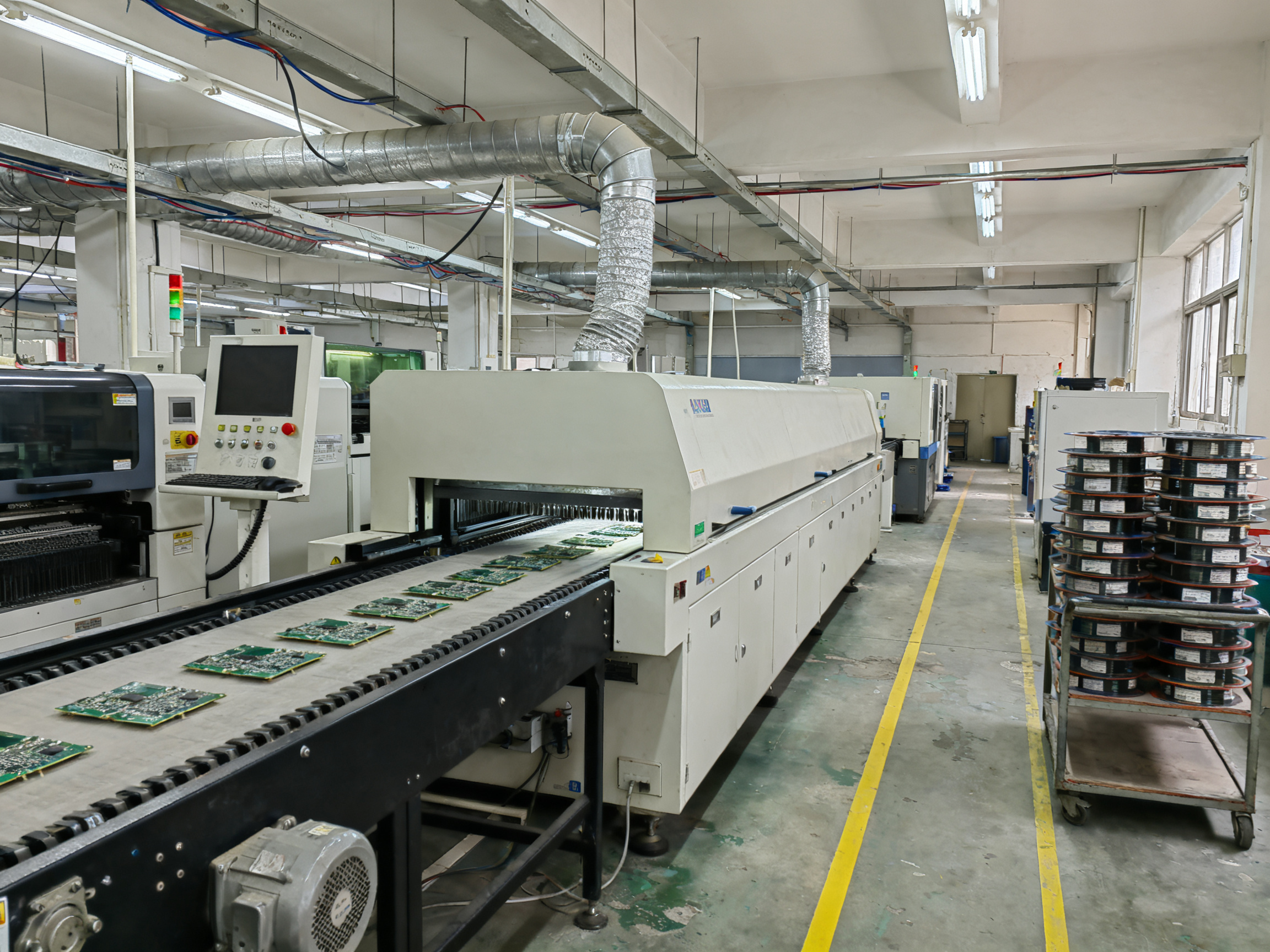
Production line features worth asking about
Modern ovens are not just heaters. Typical capabilities include recipe storage for saved profiles, conveyor width adjustment, profile verification and alarm limits, and logging that supports traceability.
| Configuration | What it adds | Watch for |
| — | — | — |
| Batch oven | Low capital cost, flexible job mixing | Operator loading consistency, longer cycle times |
| Conveyor oven | Zones, throughput, line integration | Floor space, conveyor changeover time |
| Nitrogen option | Lower oxidation, more wetting margin | Gas cost, benefit depends on paste and finish |
| Vacuum option | Fewer voids in suitable area array joints | Not a universal cure, needs an X ray acceptance method |
Nitrogen and vacuum are worth flagging because buyers often assume they are free upgrades. Nitrogen can help in specific paste and surface finish conditions, and vacuum can reduce voiding in power and area array joints, but neither is proven across the board. Ask for the defect data that justifies it on your product.
Line integration is a real feature
Downstream of the oven, an IPC-CFX connected line can exchange manufacturing data with other machines. For most shops, SMEMA style handoffs still handle basic machine to machine signals, while IPC-HERMES-9852 carries richer board metadata. If your customer demands board genealogy, specify recipe identity, board IDs, profile records, and data retention in the purchase order rather than assuming they come free.
What an oven costs you besides the purchase price
More floor space, more maintenance, calibration, and profiling discipline. Operators have to pick the right program, verify airflow, confirm thermocouple placement during setup, and keep board position consistent inside the zones. That discipline is the price of repeatability, and it is worth it once volume justifies it.
[Diagram: a five zone conveyor oven cross section showing preheat, soak, reflow, cooling, and exit zones with a conveyor path and thermocouple routing, plus a factory line visual running printer, pick and place, oven, AOI, and downstream handling.]
Next, we get into the numbers that decide everything: what reflow temperature actually means and how to build a profile you can trust.## 4. Reflow Station vs. Reflow Oven: Key Differences
Now the part everybody actually argues about. A reflow station versus a reflow oven is not a quality ranking, it’s a fit question. The bench station wins on flexibility and cost. The oven wins on consistency and volume. Here’s the side by side view.
| Factor | Reflow station (hot air or hot plate) | Batch reflow oven | Conveyor reflow oven |
| — | — | — | — |
| Heat area | One board or one spot at a time | Whole chamber, one board or tray | Whole board through separated zones |
| Ideal volume | 1 to a few boards per run | Low volume, high mix, NPI | Medium to high volume, repeatable runs |
| Repeatability | Operator dependent | Good | Very good, zone controlled |
| Operator skill | High | Medium | Lower, once the recipe is set |
| Profiling effort | Manual, frequent | Every new product | Every new product, then monitored |
| Automation | Limited | Limited | Conveyor and line integration |
| Traceability | Notes and logbook | Recipe and logs | Recipe, board IDs, profile records, MES links |
| Investment band | Low, roughly hundreds of dollars for bench units | Low to mid, thousands of dollars | Mid to high, thousands to tens of thousands |
| Primary use | Prototypes, repair, rework | Prototyping, small batches, pilot work | Continuous production |
Read the investment row as a screening signal, not a quote. Configuration, condition, shipping terms, installation, service, and warranty move the final number a lot, so get three written like-for-like quotes before you sign anything. Current buying guides for 2026 reflow oven options give rough ranges, which is about as far as public pricing reliably goes.
Where each tool fits the job
Engineering prototype. Station. You want to see the board the whole time, change a component mid-session, and finish before lunch.
Repair depot. Station, or a dedicated rework station if you do BGA and QFN work all day. Speed and control of the nozzle beat volume here.
Low volume, high mix cell. Batch oven. You change recipes several times a day and board sizes jump around. A chamber that treats the whole board evenly beats a hand-held nozzle.
Pilot line. Small conveyor oven. You want to learn conveyor loading, takt time, and recipe discipline before the line grows.
Mass production. Conveyor oven with multiple zones, cooling, and profile logging. This is where uniformity, uptime, and traceability pay for themselves.
They’re usually partners, not rivals
Most factories that own both use them for different jobs. The oven does the primary assembly on every board that comes off the placement machine. The station handles diagnosis, single-part replacement, and touch-up when a board fails inspection. We see this split in military, semiconductor, and consumer electronics lines alike, and it’s why Chuxin builds both benchtop and production oven lines.
Pro Insight: Compare equipment on cost per conforming board, not purchase price. Divide total ownership cost (equipment, options, installation, power, gas, consumables, calibration, training, labor, downtime, scrap, and rework) by the number of boards that actually pass inspection. A cheap station that needs two operator hours and a 3 percent scrap rate can cost more per good board than an oven that runs unattended on a saved recipe.
The decision tree
Do you build fewer than 5 boards a day, or mostly repair work?
  YES -> Reflow station (hot air or hot plate, add preheater)
  NO  -> Do board sizes change often, and volume stays under a few hundred a week?
           YES -> Batch reflow oven
           NO  -> Do you need line integration, board IDs, and saved profile records?
                    YES -> Conveyor reflow oven with zones, cooling, and logging
                    NO  -> Small conveyor oven is the sensible middle ground
One last thing. Whatever you pick, the station display or the oven recipe is not the process. The board is the process. Profile it, write it down, and recheck after any change to paste, stencil, board revision, or component mix.
Next: the numbers behind the profile, how to reflow a board with each method, and the defects each setup tends to create.## 9. Pro Insight: Evaluate Cost per Conforming Board
Pro Insight: Compare equipment on cost per conforming board, not purchase price. Add up everything the process costs (equipment, options, installation, power, gas, consumables, calibration, training, labor, downtime, scrap, and rework) and divide by the number of boards that actually pass inspection. A cheap bench station that needs two operator hours and a 3 percent scrap rate can cost more per good board than an oven that runs unattended on a saved recipe.
Building the model
Most purchase orders only show the first line. The real number shows up a year later, and it looks nothing like the sticker price.
| Cost line | Station setup | Oven setup |
| — | — | — |
| Capital | Low, often a few hundred dollars | Low to mid for batch, thousands plus for conveyor |
| Installation and facility | Bench space, basic power | Floor space, exhaust, possibly nitrogen or vacuum hookups |
| Profiling hardware | K-type thermocouple and a board to sacrifice | Multi-channel board, profiler, and software |
| Consumables | Paste, no-clean flux, nozzle tips | Paste, stencil wipes, filters, belt maintenance |
| Labor per run | Direct operator presence, loading and watching every board | Recipe selection, loading, then monitoring by exception |
| Yield risk | Operator dependent, so first-pass yield swings with the person on shift | Recipe locked, so the same board gets the same cycle |
| Hidden costs | Scrap, rework, and second-repair returns | Scrap, rework, and line downtime if the oven is the bottleneck |
The scrap and rework row is where the comparison usually flips. A station that works beautifully for the engineer and then needs a rework pass for 1 in 20 boards on a night shift carries a cost that never shows up on the purchase order. Acceptance criteria for what counts as a good board come from the standard your customer signs off on, such as IPC-A-610 acceptability rules, so “conforming” needs a written definition in your own work instruction rather than a gut feeling.
An illustrative calculation
Here is a made-up example, clearly labeled as such, to show the shape of the math. It is not measured factory data, and no verified 2026 case study of this kind was available to cite.
Say your plant runs 20,000 boards a year.
- Station method: $600 in equipment, plus 2.5 labor hours per run across 500 runs (1,250 hours) at $22, plus 3 percent scrap and rework on 600 boards at $4 each, plus $300 in profiling consumables. Total lands near $31,000, or about $1.55 per board attempted, and roughly $1.60 per board that passes.
- Oven method: $18,000 amortized over five years ($3,600), plus $1,200 in power and gas, plus $900 in maintenance and calibration, plus 400 labor hours at $22 ($8,800), plus 0.5 percent scrap on 100 boards ($400), plus $1,000 in profiling and consumables. Total lands near $15,900, or about $0.80 per board attempted, and roughly $0.80 per board that passes.
Change the assumptions (higher scrap, cheaper labor, bigger volume) and the answer moves. That is exactly why the numbers have to come from your own line, your own defect taxonomy, your own inspection method, and your own hourly labor rate. Do not build a business case on a borrowed number.
What to collect before you sign
You cannot build this model from a website, so gather the inputs yourself:
- Baseline defect and scrap rate by defect type, not just a total percentage
- Rework labor hours per board and per failure type
- Actual operator hours per run for both methods
- Power draw, gas consumption, and facility changes
- Changeover time when recipes switch
- Inspection method and who performs it, since X-ray and AOI cost more than eyes
Independent purchasing guides give broad 2026 price bands for production reflow ovens, which is useful for screening, but get three written, like-for-like quotes before you compare anything. If your product mix is lead-free consumer electronics, semiconductors, or military assemblies, ask a supplier like Chuxin to quote the whole line, ovens plus wave soldering plus line integration, so the comparison covers throughput and not just the heating chamber.## 5. Reflow Temperature: Building a Safe Thermal Profile
Here is where most first-time reflow jobs go sideways. Someone asks what temperature to use, gets a confident answer from a forum post, sets the iron to that number, and ends up with a board full of cold joints or a cracked capacitor. So let’s be direct about the answer.
What is reflow temperature? It is not one number. It is a time versus temperature curve with five parts, and every part has a limit set by your solder paste, your components, and your board.
[Diagram: time-temperature profile chart. Y-axis labeled temperature in C from 0 to 260, X-axis labeled time in minutes from 0 to 12. Curve segments labeled: ramp up (room to 150 to 200 C), soak plateau at 150 to 200 C, spike to peak 235 to 245 C, short dwell above liquidus, then controlled cool down. Liquidus line at 217 C drawn as a dashed horizontal reference.]
The five things your curve has to do
| Profile segment | What it controls | Example range for a common SAC305 lead-free paste | What sets the limit |
| — | — | — | — |
| Ramp rate | Protects flux and laminate | 1 to 3 C per second | Paste datasheet maximum ramp rate |
| Soak zone | Activates flux before melting | 150 to 200 C for 60 to 180 seconds | Paste and flux activation window |
| Time above liquidus | Governs wetting and joint formation | 45 to 120 seconds above 217 C | Paste datasheet, package size |
| Peak temperature | Actually melts the alloy | 235 to 245 C | Paste datasheet and component rating |
| Cooling rate | Limits joint and package stress | 2 to 6 C per second | Component supplier guidance |
Read the third column as a starting point for a typical lead-free paste, not as permission. The fourth column is where the real answer lives, and it comes from the datasheet of the paste you actually bought.
Why the same board needs different settings on different days
Component mass changes the thermal response. A 0402 resistor and a 48-pin QFN do not heat at the same rate, and the same board with one part swapped from a plastic package to a ceramic one can drift outside its window. Board thickness, copper coverage, and solder mask color all shift the numbers too. Copper pulls heat away from the joint, while a heavy thermal pad under a power device pulls it in the other direction.
Two things also change the acceptable window rather than the curve itself. Moisture sensitivity level on the component sets how much bake time the part needs before reflow, and the maximum body temperature rating sets how close to the edge you can run. The IPC/JEDEC J-STD-020 standard covers package sensitivity and handling, while JEDEC JEP30-A100 maps those ratings to assembly process temperatures.
Hot air rework station temperature: start with limits, not folklore
For hot air rework work, the same principle applies with one extra wrinkle. The air temperature at the nozzle is not the joint temperature. Nozzle size, distance, airflow, and the mass of the part under the nozzle all shift the result, so the number on the controller is only a starting point. Work from the lowest airflow and temperature that completes the joint, then raise slightly. Component suppliers publish their own limits, and OSRAM’s lead-free reflow guidance for LEDs is a good example of how tight those windows can be on sensitive parts.
One important distinction. Reflow temperature for a full board means heating the whole assembly through a controlled cycle. Rework temperature means heating one joint, and the risk profile is different because nearby parts sit in the hot zone too. A part rated for a 260 C reflow peak can still be damaged by a 260 C air stream held too long.
Safety Note: Do not copy a universal hot air temperature from a video, a forum post, or another shop. Follow the solder paste datasheet, the component manufacturer specification, the board material limits, and your equipment manual. If those four disagree, the paste and component documents win, and the profile gets validated on a sacrificial assembly before anything real goes through.
Building the profile you will actually run
Start with the paste datasheet. It usually lists a recommended preheat range, soak time, peak temperature band, and maximum time above liquidus. Those become your targets.
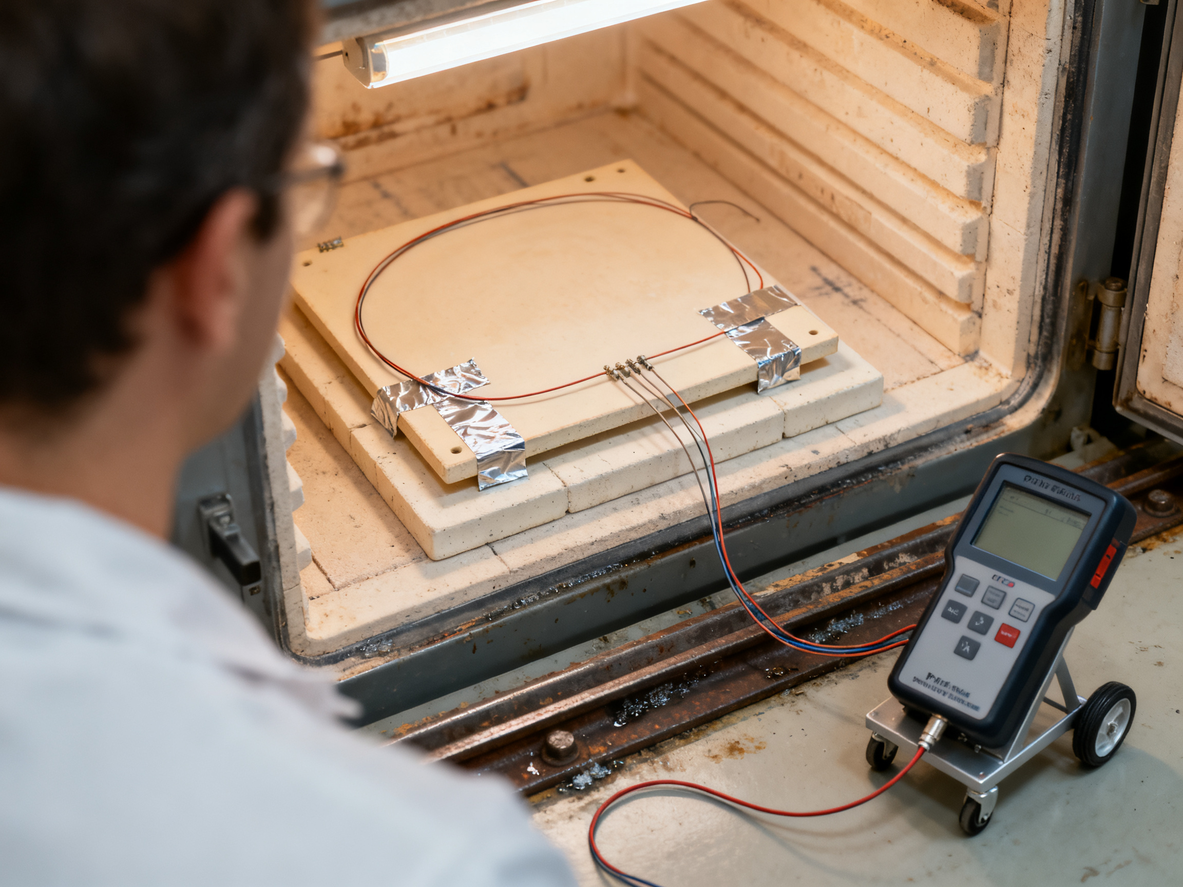
Then measure a real board. Place a K-type thermocouple at a joint that represents your cold spot, and a second one at the joint that represents your hot spot, which for a board with a big ground pour is often a small pad near that pour. Run the cycle, log peak, time above liquidus, ramp, soak, and cooling, and compare against the datasheet.
Adjust one variable at a time. Need faster cooling? Add a fan or shorten the cool-down hold. Slower ramp? Reduce the ramp setting or open the preheat earlier. Time above liquidus too short? Raise peak slightly or slow the approach to it, but do not push past the paste’s peak limit to buy time.
And validate both extremes before you release the recipe to production. The coldest joint decides whether solder wets. The hottest component decides whether the part survives. They are usually not in the same place.
Up next: how to reflow a circuit board with each method, step by step, and the defects each setup tends to cause.## 6. How to Reflow a Circuit Board With Each Method
Knowing how to reflow a circuit board comes down to two things: what you heat, and how you know the heat worked. The sequence below covers both methods. It is a high-level overview, not a substitute for an approved work instruction or a trained operator.
How to use a reflow station
- Inspect and protect. Check the board for damage, clean the pads, and confirm the part matches the footprint.
- Apply paste or flux. For a new joint, print or dispense solder paste. For rework on an existing joint, a thin coat of no-clean flux usually does more good than adding fresh paste.
- Align and secure. Position the component with a pick and place tool or tweezers, and make sure it will not slide when the solder melts.
- Preheat. Bring the board up slowly so the whole assembly warms together and thermal shock stays low.
- Apply controlled heat. Hold the hot air reflow station nozzle about 1 to 2 cm above the joint with medium airflow, then lower the temperature setting until the solder flows. Watch the joint, not the display.
- Cool undisturbed. Set the part down and let it solidify without movement.
- Clean and inspect. Clean if your process requires it, then check the joint under magnification.
How to reflow in an oven
- Verify paste and stencil. Check paste condition, stencil aperture, and print quality before placing anything.
- Place components. Standard SMT placement, with the paste still printable underneath.
- Load a validated recipe. No improvising at the line.
- Attach thermocouples during setup. Profiling and production are separate activities, and the setup thermocouples come off before the run.
- Run the board. Board position inside the zones matters, and conveyor speed sets your dwell time.
- Inspect and test. Visual first, then AOI, X-ray for hidden joints, and electrical test.
- Document deviations. A temperature alarm or a hold-up in the line belongs in the log.
Acceptance checks
| Check | What it catches | Notes |
| — | — | — |
| Visual inspection | Bridging, insufficient solder, tombstoning | IPC-A-610 acceptability rules |
| AOI | Solder volume, missing parts, polarity | Works well on visible joints |
| X-ray | Voids, bridging under BGA and QFN | Shows geometry, not every metallurgical issue |
| Electrical test | Opens, shorts, functional faults | Catches what the eye cannot |
| Controlled rework | Fixing defects without new ones | Follow IPC-7711/7721 procedures |
[Diagram: side-by-side numbered process flow, station workflow on the left with nozzle and preheater, conveyor oven workflow on the right with zones, thermocouple, and conveyor path.]
Printable setup checklist
- [ ] Paste or flux selected and at temperature
- [ ] Component orientation confirmed
- [ ] Thermocouple attached at cold and hot points
- [ ] Recipe matches the board revision
- [ ] Board loaded square in the zone
- [ ] Preheat reached before peak
- [ ] Board cooled without movement
- [ ] Inspection method and limit set
- [ ] Settings and deviations logged
One last thing about how reflow works at the material level. What is reflow solder, exactly? It is the alloy doing the joining, and its liquidus point is what the profile must cross. If you know your alloy and its limits, the machine choice matters less than the profile you run on the board.
Next, the defects these two methods tend to cause, and why equipment choice shifts the failure list.## 7. Common Reflow Defects and How Equipment Choice Affects Them
Every reflow defect traces back to one of three things: the profile, the paste, or the handling. Sometimes the fix is a process tweak. Sometimes the tool simply lacks the control you need.
Defect matrix
| Symptom | Likely cause | Diagnostic method | Corrective action |
| — | — | — | — |
| Insufficient wetting | Too little time above liquidus, cold joint, contaminated pad | Cross-section, visual at 10x | Extend time above liquidus, clean pads, refresh paste |
| Bridging | Excess paste volume, poor stencil aperture | Visual, AOI | Reduce aperture, verify print, check paste viscosity |
| Solder balls | Flux not activated, rapid ramp, spatter | Visual | Slow the ramp, extend soak, check paste condition |
| Tombstoning | Uneven heating, one-ended joint formation, poor wetting | Visual, X-ray | Improve wetting, lower heating gradient |
| Voiding | Entrained gas, outgassing, insufficient soak | X-ray | Longer soak, check paste outgassing, consider vacuum |
| Head-in-pillow | Package lifted during solidification, cooling too fast | X-ray | Slow the cool-down, hold position, improve support |
| Opens | Cold joint, insufficient solder, pad damage | Electrical test, cross-section | Re-profile, inspect paste print |
| Component shift | Placement error, molten solder flow, vibration | Visual | Fix placement, verify solder volume, steady the board |
| Board warpage | Uneven heating, thermal stress | Measure, visual | Balance top and bottom heat, slow the ramp |
| Heat damage | Package or laminate over temperature | Component analysis | Cut peak and dwell time to datasheet limits |
Where equipment choice shows up
Localized heating with a hot air reflow station creates steep gradients. Neighbors on the same board can sit at very different temperatures, so bridging, tombstoning, and head-in-pillow tend to cluster around the heated area. Repeatability also shifts with the operator’s nozzle distance and air setting.
An oven treats the whole board as one thermal object, so defects shift character. They become board-wide: cold corners from slow heating, solder balls from an aggressive ramp, or a whole run damaged by a peak set too high. The oven gives better uniformity, but a bad recipe then damages every board that passes through.
Inspection support matters too. BGA and QFN reflow work needs X-ray to see hidden joints. A station with no way to log profiles leaves you with a display reading and a guess.
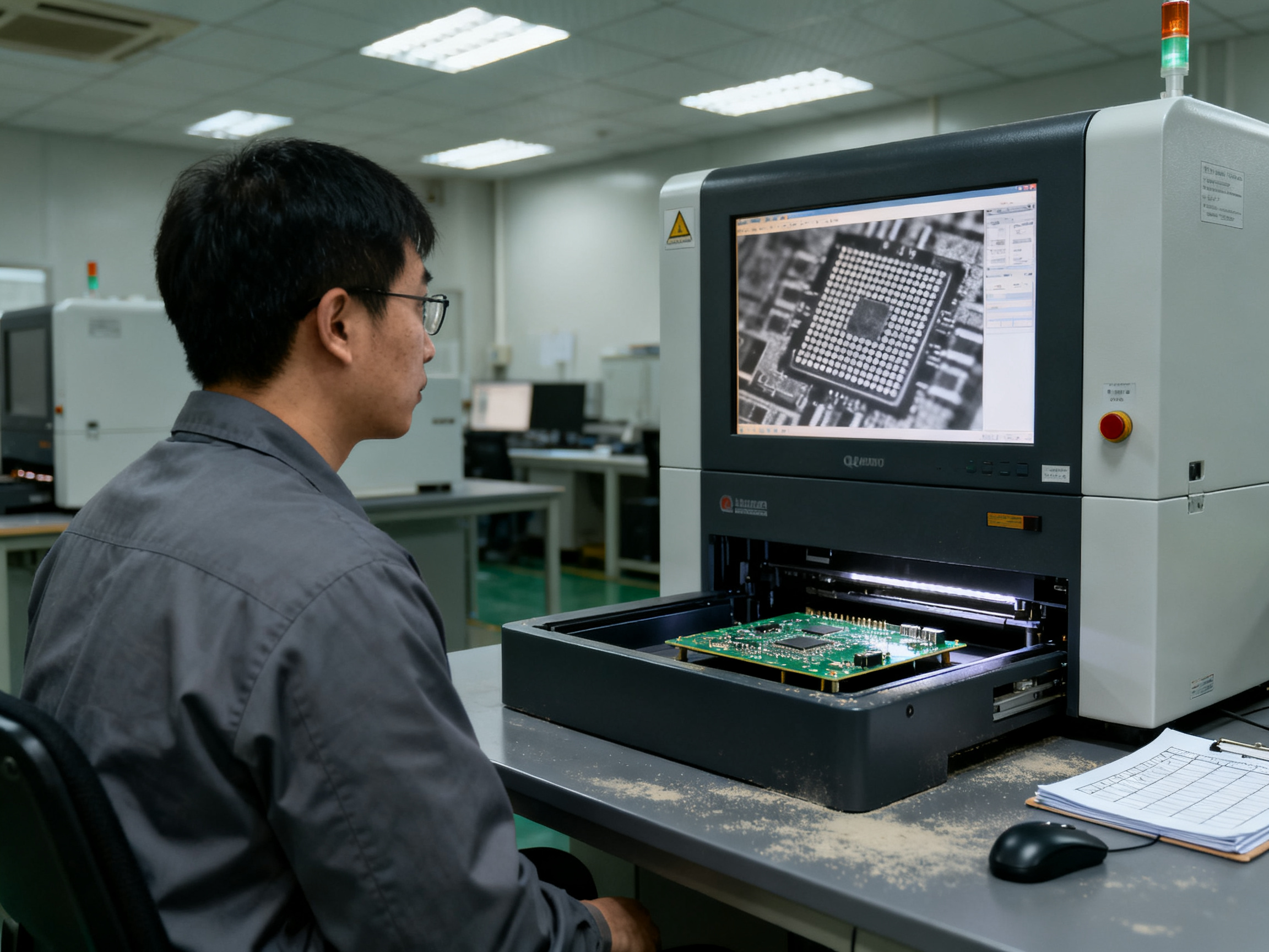
Process Validation Principle: Start validation with the hardest or most thermally demanding assembly in your portfolio, not the easiest. The cold joint governs wetting and the hottest package governs damage; profiling both ends of that range, as recommended in IPC-hosted BGA profiling guidance, tells you whether the equipment you chose can actually hold the window.
So, tuning first. If the same defect survives a corrected profile, clean paste, and good placement, the problem is the machine: not enough thermal control, no logging, no inspection path. That is when the upgrade conversation starts.
If you want to see what a full line looks like before you commit, ask suppliers like Chuxin to quote ovens, wave soldering, and line integration together. Defect rates usually trace back to the whole process, not one heater.## 13. Process Validation Principle: Validate the Hardest Assembly First
Process Validation Principle: Start validation with the hardest or most thermally demanding assembly in your portfolio, not the easiest one. The cold joint governs wetting; the hottest package governs damage. Profile both ends of that range before you release any recipe to production. This article was written from published technical sources rather than a named author, so the guidance below is cited, not presented as first-hand factory experience.
Why the easy board lies to you
A clean two-layer board with 0402 passives and a handful of through-hole parts will almost never expose a thermal problem. Profile it and you will see a clean curve, a comfortable margin, and an easy approval. Then the same recipe meets a dense BGA array next to a heavy thermal pad on a six-layer board, and the numbers stop matching.
The gap comes from a handful of variables that scale fast:
| Risk factor | What it changes | Where to look |
| — | — | — |
| Package density | Shadowing, local soak time | Between rows of fine-pitch pads |
| Thermal mass | Lag behind the air temperature | Heavy thermal pads, large ground pours |
| Copper coverage | Pulls heat away from the joint | Pour edges, power planes |
| Board size and asymmetry | Cold corners, uneven cooling | Center versus edge of the panel |
| Component limits | Narrower acceptable window | Sensitive packages, moisture-sensitive devices |
| Reflow passes | Cumulative thermal load | Boards that see the oven twice |
IPC-hosted BGA profiling guidance recommends thermocouples at the BGA center and the corner to measure delta-T and confirm that the balls actually reflowed. That same logic generalizes to any product family.
How to build the worst-case board set
For a family of products, make a short risk matrix instead of guessing. Screen the boards, then profile at least these locations where the design allows it:
- BGA center and corner, so you can read the delta-T across the package
- QFN exposed pad and a peripheral pad, which heat differently by design
- Board center and board edge, because they cool differently
- A small pad sitting on a large copper pour, which is usually the cold spot
- The most temperature-sensitive part on the board
Record peak temperature, time above liquidus, ramp rate, soak time, cooling rate, and the temperature difference across the board. Confirm the joints with X-ray. If a defect needs a real answer, cross-section a sample or run it through electrical and mechanical test. X-ray shows geometry, not every metallurgical problem.
Then repeat the whole thing after any change to board revision, package, paste, stencil, oven, recipe, or rework method. A profile you validated in March is not a validated profile in September.
What worst-case validation actually buys you
Running the hard board first tells you early whether your equipment can hold a window at all, before hundreds of boards are committed. If the hardest assembly profiles clean with margin, the easy ones will follow with little fuss. If it does not, you have found the problem while it is still an engineering question, not a field return.
One caution on framing. I could not verify a 2026 production case study quantifying how often easy-board validation leads to a specific downstream failure, so treat this as sound process reasoning rather than a measured statistic. Run the numbers on your own line, with your own defect taxonomy and inspection method.
Up next, we pull it all together and pick the option that fits your volume, board mix, and budget.## 14. Conclusion: Which Reflow Solution Should You Use?
Pick a reflow station when the work is targeted and flexible: repair, engineering changes, prototypes, and low-volume builds where you want to watch the board the whole time. Pick a profiled reflow oven when you need repeatable cycles, line integration, saved recipes, board traceability, and output you can scale. Advanced packages, tight yield targets, or tough thermals may also justify nitrogen, vacuum, or dedicated rework equipment, though none of those are automatic upgrades.
Here is the checklist to run before you commit:
- Product mix: how many boards, how many variants, how often do recipes change?
- Package types: BGA, QFN, and other area-array parts push you toward ovens and X-ray inspection.
- Board dimensions and copper coverage: bigger boards hold more heat and profile less predictably.
- Alloy: SAC305, SnBi, or something else, and what liquidus does that imply?
- Required yield: what does your customer sign off on under IPC-A-610 acceptability rules?
- Takt time and volume: what output do you actually need per shift?
- Operator skill: who runs the process, and how much training can you support?
- Inspection capability: visual, AOI, X-ray, electrical test.
- Standards and rework: which procedures govern the work you touch.
- Integration: conveyors, MES, board genealogy, IPC-CFX and HERMES data exchange.
- Service support and total cost of ownership: cost per conforming board, not sticker price.
Whichever way you go, profile the real assembly, document the recipe, and recheck after any change.
If you want a second set of eyes on your line, Chuxin (S&M Co. Ltd.) quotes reflow ovens, wave soldering, and full line integration together, and they will map a configuration to your product mix and takt time. Ask for a process evaluation, not just a quote.